

Page 1

MDT3 and MDT4 Service Parts
This parts lists contains part numbers for the
service parts available for the MDT3 and MDT4.
They have been manufactured in both 60 Hz and
50 Hz models.
The 60 Hz models are:
MDT3F12-1A or MDT3F12A-1H
·
MDT4F12-1A or MDT4F12A-1H
·
The 50 Hz models are:
MDT3F12-6A or MDT3F12A-6H
·
MDT4F12-6A or MDT4F12A-6H
·
Always check the model number of the ice
machine being serviced to be certain that the
parts ordered will be correct.
Table of Contents
Cabinet ·········································································································································· Page 2
Condensing Components ············································································································· Page 3
The service parts for the evaporator changed in
April of 2010.
A contactor was added in early 2011, the first
unit with one was MDT4F12A-1H serial number
11011320013662.
Evaporator, Auger, Bearings & Water Seal ················································································· Page 4
Water And Drain System ·············································································································· Page 5
Bin Cover, Dispenser Motor, Electric Eyes ·················································································· Page 6
Prior Gear Reducer and Motor - A31977 type ············································································· Page 7
Gear Reducer 02-4399-21 or 02-4399-24 or 02-4398-21 ···························································· Page 8
Control Box ··································································································································· Page 9
MDT4 60 Hz Wiring Diagram (w/out contactor) ··········································································· Page 10
MDT3 Wiring Diagram (w/out contactor) ······················································································ Page 11
Schematic Diagram (all w/out contactor) ····················································································· Page 12
MDT4 50 Hz Wiring Diagram (w/out contactor) ··········································································· Page 13
MDT3 or MDT4 Wiring Diagram with Contactor (change in early 2011) ····································· Page 14
MDT3 or MDT4 Schematic Diagram with Contactor ···································································· Page 15
January 2011
Page 1
Page 2
MDT3 and MDT4 Service Parts
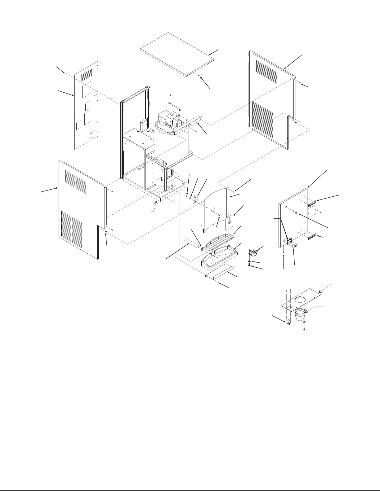
Cabinet
3
27
25
31
23
15
Item Part
Number Number Description
1 A37767-001 Cabinet top, S.S.
2 A37783-001 Right side panel, SS
3 03-1638-03 Screw
4 03-1419-17 Screw
5 15-0809-01 Emblem, Scotsman
6 15-0803-01 Emblem, Touch-Free
7 12-1377-00 Switch
8 03-1403-15 Screw
9 03-1406-04 Nut
10 02-3944-01 Spout
11 03-1407-03 Washer
12 03-1403-19 Screw
13 02-3302-02 Grill
14 03-1418-30 Machine screw
15 13-0674-07 Tube, order 3 units.
16 02-3402-32 Sink - grey
17 A35875-015 Bracket
18 02-2814-10 Hose clamp
19 12-2551-20 Touch free sensor
20 17-2830-01 Decal
9
11
18
Item Part
Number Number Description
August 2008
Page 2
28
19
3
14
1
4
26
20
13
16
17
3
32
10
11
12
8
2
3
24
5
21
6
7
30
29
22
21 12-2391-01 Lock, Gov’t units only
22 12-2501-01 Touch Free disable switch
23 03-3804-01 Screw receptacle
24 A37766-021 Front panel, incl # 5,6,32
A37766-002 Front panel, Gov’t units
25 A37784-001 Left side panel, SS
26 02-3878-31 Splash panel - grey
27 A37875-001 Back panel
28 A37873-001 Support bracket
29 02-3944-01 Clear spout, replaced item
10 in May 2002
30 A36547-001 Mounting plate for spout
31 13-0566-01 Bottom gasket - complete
32 17-2831-01 Water decal
Page 3
MDT3 and MDT4 Service Parts
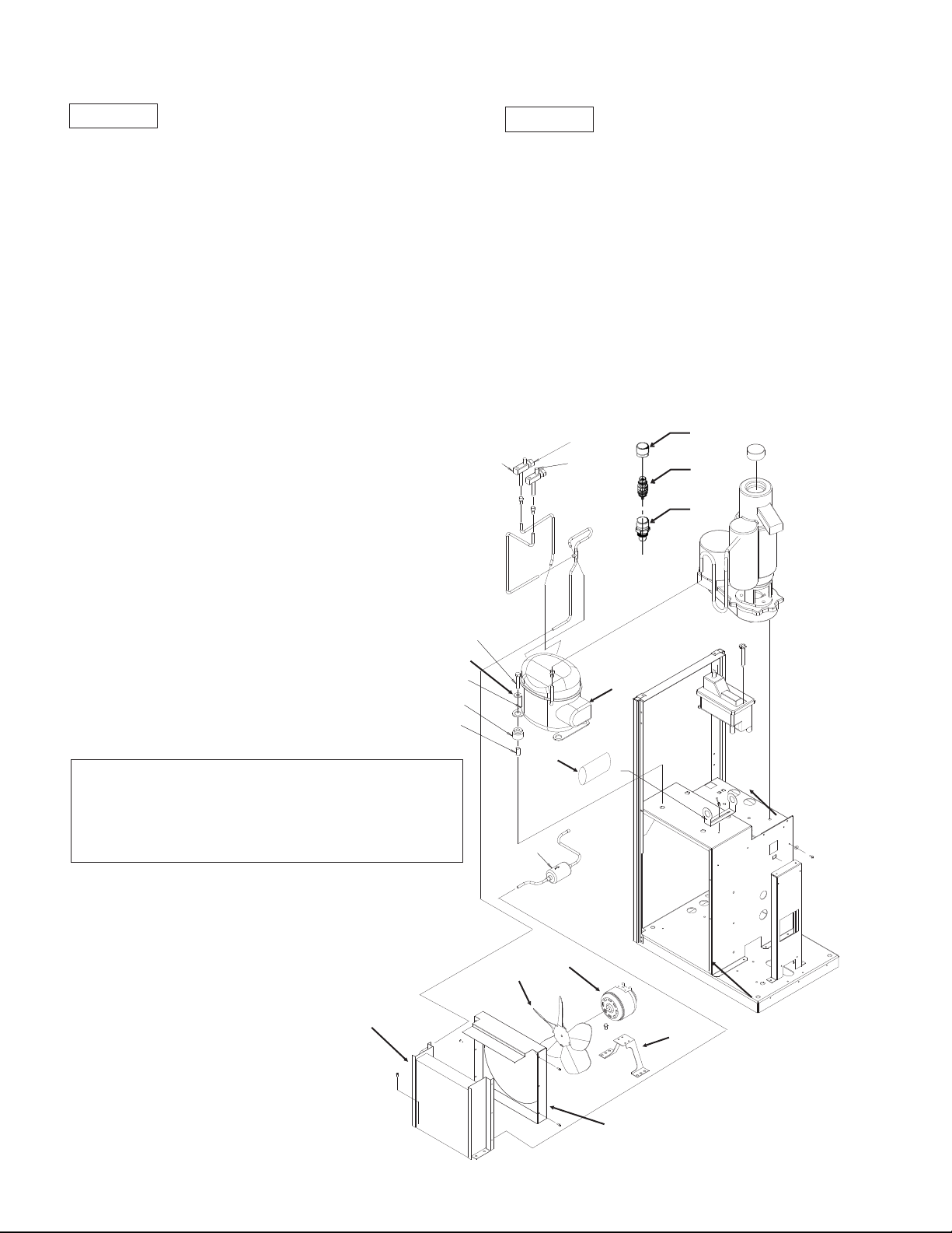
Condensing Components
MDT4F12
Item Part
Number Number Description
1 18-8741-21 60 Hz compressor
18-8741-26 50 Hz compressor
2 18-8741-27 Overload for 60 Hz
18-8741-22 Overload for 50 Hz
18-8741-28 60 Hz relay
18-8741-23 50 hz relay
3 18-8741-29 Start capacitor for 60 Hz
18-8741-24 Start capacitor for 50 Hz
4 18-8849-01 60 Hz fan motor
18-7200-03 50 Hz fan motor
5 18-8858-01 Fan blade for 60 Hz
18-8743-01 Fan blade for 50 hz
6 A37839-001 Fan shroud for 60 Hz
A36094-001 Fan shroud for 50 Hz
7 03-1405-40 Screw
7a 03-1407-02 Washer
7b 18-4700-28 Grommet
8 18-0108-41 Sleeve
9 16-0832-21 Access valve
9a 16-0832-03 Core cap
9b 16-0832-02 Stem cap
10 18-0422-00 Fan motor bracket
11 18-8846-01 Condenser
12 02-3319-01 Drier
7a
7b
8
MDT3F12
Item Part
Number Number Description
1 18-8853-21 60 Hz compressor
18-8853-26 50 Hz compressor
2 18-8853-27 Overload for 60 Hz
18-8853-22 Overload for 50 Hz
18-8853-28 60 Hz relay
18-8853-23 50 hz relay
3 not used
4 12-1681-23 60 Hz fan motor
12-1681-04 50 Hz fan motor
5 18-8851-01 Fan blade
6 A37813-001 Fan shroud
9a
9
9b
9a1
9a2
9a3
7
1
2
Access Valve Change - November 2007
9a1 16-1140-01 Cap
9a2 16-1139-01 Core
9a3 16-1138-01 Seat for 1/4" tube
11
3
12
4
5
10
6
November 2007
Page 3
Page 4
MDT3 and MDT4 Service Parts
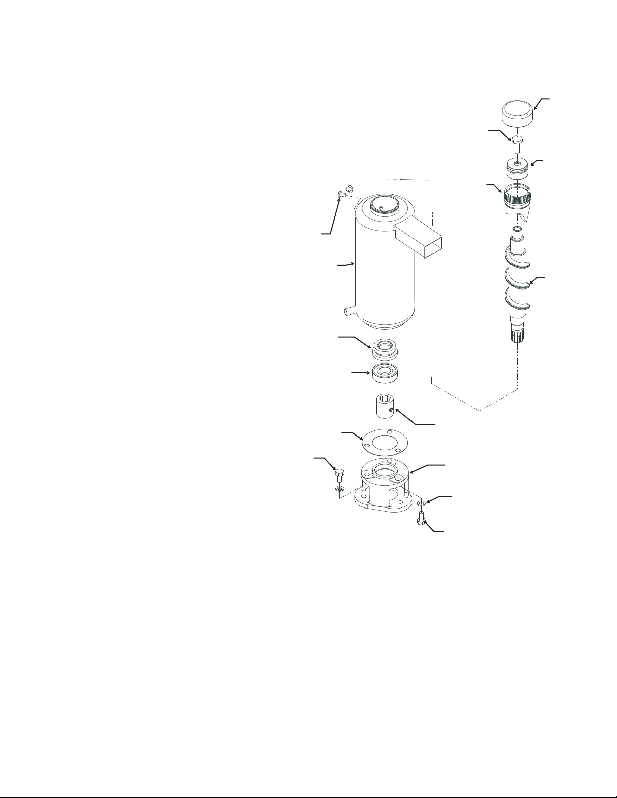
Evaporator, Auger, Bearings & Water Seal
ITEM PART
NUMBER NUMBER DESCRIPTION
1 02-4404-02 Threaded cap - grey
2 03-0758-00 Screw
3 02-4535-01 Top bearing, w/thrust washer - for updated units*
4 02-4575-21 Breaker kit, includes items 1, 3, 4a, 4b, 7 & 7a*
4a 13-0617-16 O-Ring (inside)
4b 13-0617-37 O-Ring, outside of breaker
5 02-4600-20 Auger - for updated units*
6 A36081-020 Evaporator
7 03-1417-07 Washer
7a 03-1403-46 Screw
8 02-4599-21 Water Seal
9 02-0417-21 Lower Bearing
10 03-1505-00 Gasket
11 08-0595-01 Adapter
12 03-1405-38 Cap Screw (3)
13 03-1420-01 Cap screw
14 03-1410-04 Washer (3)
15 A29915-002 Spline Coupling
16 02-4578-02 Auger and bearing kit
Includes items 1, 2, 4, 4a, 4b, 5, 7, 7a, 8, and 9
17 19-0662-02 Top bearing grease, 13 oz tube
Note: Use about 1 oz per bearing. Lightly coat
bearing surfaces, throughly grease thrust portion
of bearing (horizontal needles).
* Updated units use listed auger and top
breaker and bearing.
Update availability began Feb. 2010. Updated
units and later production units have grey cap to
indicate use of this type of top bearing and auger.
Non-updated units or units with white or brass cap
require auger kit item 16 when replacing top
bearing or auger.
Production with listed bearing and auger began in April 2010 and have a grey
cap. Prior top bearing and auger are no longer available.
7, 7a
6
8
9
10
12
1
2
3
4, 4a, 4b
5
15
11
14
13
April 2010
Page 4
Page 5
MDT3 and MDT4 Service Parts
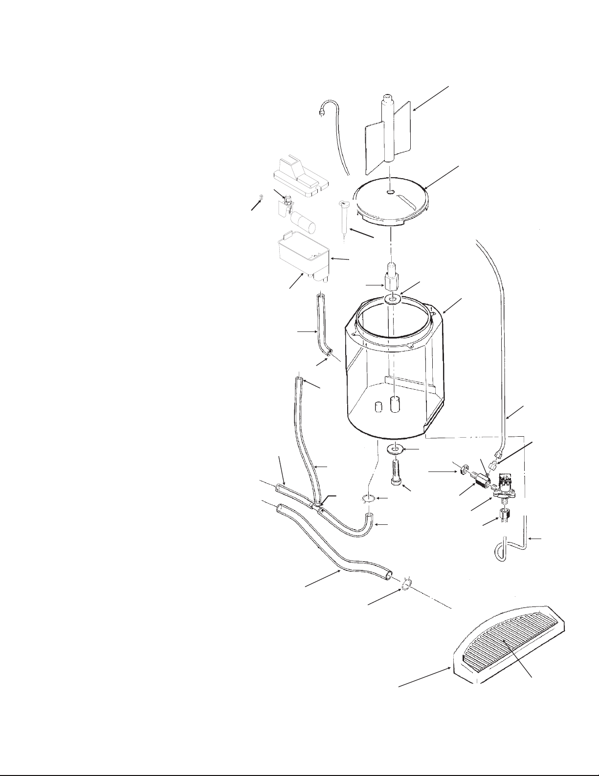
Water And Drain System
Item Part
Number Number Description
1 A37893-001 Vane Assembly
2 A38272-001 Bin Bottom Assy
3 02-3033-01 Hub Assembly
4 03-1409-22 Fiber Washer
5 A36118-020 Storage Bin
6 13-0895-01 Inlet water line
requires 26"
7 03-1394-00 Pal Nut
21a
8 12-1434-04 Water valve
(60 Hz)
12-1434-05 Water valve
(50 Hz)
9 16-0869-01 Barbed adapter
10 02-4200-01 Preformed tube
11 A33101-022 Water sensor
12 02-3402-32 Sink
13 02-3302-02 Grill for sink
14 13-0674-07 Tube, requires 12"
15 02-2814-10 Clamps
16 13-0674-09 Tube, overflow to
drain, requires 12"
16a Bin drain, 11”
16b Drain, 9”
17 02-2814-08 Clamp
18 02-2814-07 Clamp
19 02-3371-01 Reservoir Assy
20 A36402-001 Reservoir Bracket
21 02-3371-02 Float and arm
21a 02-3266-03 Plunger/seat
22 03-1409-22 Washer
23 03-1645-01 Hex Cap Screw
24 13-0674-06 Tube (to evap.)
25 A21433-000 Inlet fitting
26 16-0870-01 NPT to compr. fitting
27 16-0871-01 Brass insert
28 16-0670-01 Tee
21
16b
20
24
14
18
17
16
28
19
15
1
2
11
23
4
22
7
5
6
27
26
25
8
9
10
3
15
16a
September 2011
Page 5
12
13
Page 6

MDT3 and MDT4 Service Parts
Bin Cover, Dispenser Motor, Electric Eyes
Item Part
Number Number Description
1 03-1403-15 Screw
2 03-1531-01 Screw
3 A35474-001 Motor Mtg. Bracket
4 02-3238-01 Bushing
5 03-0727-10 Thumbscrew
6 13-0866-01 Grommet
7 A37710-021 Electric eye set
8 02-3237-01 Bin top
9 02-3239-01 Nut
10 02-3241-01 Shaft
11 12-1610-01 Motor & gears 60 Hz
12-1610-06 Motor & gears 50 Hz
12 02-1801-02 Strap
A35483-021 Complete assembly 60 Hz (except items 5 and 7)
A35483-026 Complete assembly 50 Hz (except items 5 and 7)
1
2
12
11
7
6
3
4
5
6
8
March 2003
Page 6
7
9
10
Page 7

MDT3 and MDT4 Service Parts
Prior Gear Reducer and Motor - A31977 type
Item Part
Number Number Description
1. 12-2059-01 Switch
2. none, part of item 3
3. A27494-001 Centrifugal Sw. Kit
4. 03-1403-77 Screw
5. A30579-001 Shaft and Actuator
6. 03-1408-36 Washer
7. 02-1503-00 Grease seal
8. 03-1408-21 Washer
9. 03-1408-04 Washer
10. 02-2445-01 Output shaft
11. 03-1515-03 Retaining ring
12. 03-1602-01 Woodruff Key
13. 02-2444-01 Output gear
14. 02-1505-00 O-ring
15. 03-0774-11 Roll pin
16. A28166-001 Gear Case
17. 03-1408-39 Washer
18. 03-1408-40 Washer shim
19. 02-2439-01 2nd gear & third pinion
20. 03-1408-41 Washer
21. 03-1408-38 Washer
22. 02-2438-01 1st gear & 2nd pinion
23. A28165-021 Gear box cover
24. 02-3969-20 Grease seal
25. 02-1501-00 Bearing
31
26. 03-1408-08 Washer
27. A37707-021 60 Hz motor kit*
28. A38501-001 50 Hz motor kit*
29. A28168-001 Fan
30. A38487-001 Motor Housing with bearing
31. A32379-027 Oil
32. 02-4399-21 Complete 60 Hz Gear Motor
02-4399-24 Complete 50 Hz Gear Motor
02-4398-21 Gear reducer kit, no motor
33. A24295-001 Spacer
34 03-1408-02 Washer
35 03-1405-45 Screw
36. 13-0639-00 Grommet
* motor kit includes items 25, 26, 29 and 30.
26
21
22
28
20
21
27
29
25
20
23
30
24
19
17
36
35
16
17
18
34
7
18
33
3
1
2
4
5
8
9
10
11
12
13
9
8
14
15
MOUNTING
DETAIL
January 2009
Page 7
Page 8

MDT3 and MDT4 Service Parts
Gear Reducer 02-4399-21 or 02-4399-24 or 02-4398-21
ITEM PART
NUMBER NUMBER DESCRIPTION
1. 12-2059-01 Switch
2. A27494-001 Centrifugal Sw. Kit
3. 03-1403-77 Screw
4. A30579-001 Shaft and Actuator
5. part of item 2
6. 03-1408-36 Washer
7. 02-1503-00 Grease seal
8. 13-0947-01 Gasket
9. 03-1408-39 Washer
10. 03-1408-40 Washer shim
11. 02-2439-01 2nd gear and third pinion
12. 03-1408-41 Washer
13. 03-1408-38 Washer
14. 02-2438-01 1st gear & second pinion
15. 02-3969-20 Grease seal
16. 02-1501-00 Bearing
17. 03-1408-08 Washer
18. A37707-021 60 Hz motor kit*
A38501-001 50 Hz motor kit*
19. A28168-001 Fan
20. A38487-001 Motor Housing w/ bearing
21. A32379-027 Oil
22. 02-4399-21 Complete 60 Hz Gear
Motor Assembly with motor
02-4399-24 Complete 50 Hz Gear
Motor Assembly with motor
02-4398-21 Gear reducer kit, no motor
23. A24295-001 Spacer
24 03-1408-02 Washer
25 03-1405-45 Screw
26. 13-0639-00 Grommet
27. 13-0941-01 Water shed
18
13
14
12
13
20
19
16
15
17
11
2
1
5
3
4
6
27
7
9
10
9
* motor kit includes items 16, 17, 19, 20
Note: Wire termination on replacement motor varies
from original equipment.
January 2011
12
Page 8
26
25
23
24
Included
with item
8
MOUNTING
DETAIL
Page 9

MDT3 and MDT4 Service Parts
Control Box
1
3
3
2
4
Item Part
Number Number Description
1 12-1213-10 Snap bushing
2 12-2499-01 Stand off
3 12-2843-21 Circuit board for 115/60/1
12-2843-26 Circuit board for 220/50/1
4* 12-2469-03 Contactor, 115/60/1
12-2469-02 Contactor, for 50 Hz model
Not shown:
5 12-3042-01 Wire harness for 60 Hz model w/contactor
12-3042-02 Wire harness for 50 Hz model w/contactor
* Contactor added after MDT4F12A-1H 11011320013662.
January 2011
Page 9
Page 10

MDT3 and MDT4 Service Parts
MDT4 60 Hz Wiring Diagram (w/out contactor)
March 2003
Page 10
Page 11

MDT3 and MDT4 Service Parts
MDT3 Wiring Diagram (w/out contactor)
March 2003
Page 11
Page 12

MDT3 and MDT4 Service Parts
Schematic Diagram (all w/out contactor)
Controls shown in the ice making mode with all dispensing systems in operation.
March 2003
Page 12
Page 13

MDT3 and MDT4 Service Parts
MDT4 50 Hz Wiring Diagram (w/out contactor)
March 2003
Page 13
Page 14

MDT3 and MDT4 Service Parts
1
MOT
FAN
BK
BK
2
2
1
T2 L2
T1
L1
CONTACTOR
BK
R
WATER
SENSOR
NTC
RX/TX DISABLE
SWITCH
TX
BIN
RX
BIN
RX
ICE
TX
ICE
PIN #2
PIN #1
PIN #3
PIN #6
PIN #5
PIN #4
PIN #10
PIN #11
PIN #12
PIN #13
PIN #14
PIN #15
NO
COM
GN
BK
V
BN
BK
O
SWITCH
CENTRIFUGAL
BN
N
L
START CAPACITOR
(MDT4 ONLY)
POWER SUPPLY
SEE NAMEPLATE FOR PROPER
VOLTAGE REQUIREMENTS
AND MAXIMUM FUSE SIZE
TERM
BOARD
JUNCTION
BOX
COMPRESSOR TERMINAL
BOX
COMPRESSOR
MOTOR
MOTOR MTG.
BRACKET
R
S
C
1
3
M
S
RELAY
FREEZER
DISPENSER
MOT
MOT
WATER
TOGGLE
SWITCH
SOLENOID
WATER
= WIRE NUT
DASHED LINES IND ICA TE FIE LD WIR ING
WHICH MUST BE INSTALLED IN ACCORDANCE
WITH THE NATIONAL ELECTRICAL CODE
AND ALL STATE AND LOCAL CODES
WIRE COLOR FOR 115/60/1: WHITE
WIRE COLOR FOR 230/50/1: BLACK
USE COPPER CONDUCTORS ONLY
THIS UNIT MUST BE GROUNDED
17-3349-01
1
2
KEY LOCK
SWITCH
(WHEN REQ‘D)
V
O
BN
BN
BK BK
BK
MDT3 or MDT4 Wiring Diagram with Contactor (change in early 2011)
January 2011
Page 14
Page 15

MDT3 and MDT4 Service Parts
CONTROLS SHOWN IN THE ICE MAKING
MODE WITH ALL DISPENSING SYSTEMS
IN OPER AT ON
NTC
TRANSISTOR
CONTACTOR
L1
L2
POWER SUPPLY
PRINTED CIRCUIT
ASSEMBLY
DISPENSING
WATER
FAN
COMP
AUGER
AUGER RELAY
KEY LOCK
SWITCH
WATER
SWITCH
TX
TRANSMITTER
RX
RECIEVER
MOT
MOT
MOT
SOL
MOT
(WHEN REQ‘D.)
RX DISA BL E
RX
RECIEVER
TX
TRANSMITTER
CENT
SWITCH
CONTACTOR COIL
COMP
RELAY
MDT3 or MDT4 Schematic Diagram with Contactor
January 2011
Page 15
 Loading...