

Scotsman MCS 46 A,MCS 46 W,MCM 1210 A,MCM 46 A,MCM 46 W,MCL 16 A,MCL 46 A,MCL 1210 A,MCXL 46 W Service Manual

Page 1
Page 1
Scotsman Ice Srl
Via Lainate, 31 - 20010 Pogliano M.se - Milano - Italy
Tel. +39-02-93960.1 (Aut. Sel.)- Telefax +39-02-93550500
Direct Line to Service & Parts:
Phone +39-02-93960350 - Fax +39-02-93540449
Website: www.scotsman-ice.it
E-Mail: scotsman.europe@scotsman.it
ISO 9001 - Cert. n. 0080
MC 46
Electronic
modular cubers
New PC Board
From s.n. 28850
REV. 09/2015
SERVICE MANUAL

LED STATUS
REASON WHY - SIGNIFICATION - SIGNIFICATO
ON STEADY
FIXE
FISSO
FREEZING CYCLE
EN RÉFRIGÉRATION
IN CONGELAMENTO
BLINKING
CLIGNOTANT
LAMPEGGIANTE
60 MINUTES DELAY AT START UP JUMPER J3 OUT
60 MINUTES DE RETARD AU DEMARRAGE - CAVALIER J3 OUVERTE
60 MINUTI RITARDO PARTENZA - CONTATTI J3 APERTI
ON STEADY
FIXE
FISSO
TOO HI DISCHARGE PRESSURE/TEMP.
COUPURE HP
FERMATA ALTA TEMP. CONDENSAZIONE
BLINKING
CLIGNOTANT
LAMPEGGIANTE
TOO HI EVAP. TEMP. (> 0°C) AFTER 15’ FROM START UP
COUPURE BP ( > 0°C LU PAR LA
SONDE EVAP. NON ATTEINTE APRES 15’ FONCT.)
TEMP. EVAP. > 0°C DOPO 15’ DA INIZIO CONGELAMENTO
ON STEADY
FIXE
FISSO
UNIT OFF AT BIN FULL
CABINE PLEINE
CONTENITORE PIENO
BLINKING SLOW
CLIGNOTANT LENT
LAMPEGG. LENTO
I/R BEAM CUTTED
FAISCEAU INFRA ROUGE CELLULE NIVEAU GLACE INTERROMPU
RAGGIO INFRAROSSO INTERROTTO
BLINKING FAST
CLIGNOTANT RAPIDE
LAMPEGG. VELOCE
I/R ON AFTER TRIP OFF AT BIN FULL
FAISCEAU INFRA ROUGE CELLULE NIVEAU GLACE ETABLI
RAGGIO INFRAROSSO RIPRISTINATO DOPO FERMATA A CONT. PIENO
ON STEADY
FIXE
FISSO
I/R CALIBRATION DONE
CALIBRATION FAISCEAU INFRA ROUGE CELL. NIVEAU GLACE REALISÉ
CALIBRAZIONE RAGGIO INFRAROSSO EFFETTUATA
BLINKING
CLIGNOTANT
LAMPEGGIANTE
UNIT IN CLEANING MODE OR TRIPPING OFF AFTER TEST - JUMPER TEST IN
MACHINE EN MODE DETARTRAGE OU ARRÊTE APRES LE TEST - CAVALIER TEST FERMÉ
MACCHINA NELLA FASE LAVAGGIO O FERMA DOPO IL TEST - PONTICELLO TEST CHIUSO
ON STEADY
FIXE
FISSO
CONDENSER SENSOR OUT OF ORDER
SONDE CONDENSEUR HS
SONDA CONDENSATORE MALFUNZIONANTE
BLINKING
CLIGNOTANT
LAMPEGGIANTE
EVAPORATOR SENSOR OUT OF ORDER
SONDE EVAPORATEURS HS
SONDA EVAPORATORE MALFUNZIONANTE
BLINKING ALTERNATIV.
CLIGNOTANT ALTERNÉ
LAMPEGGIO ALTERN.
I/R SENSOR OUT OF ORDER
SONDE INFRA ROUGE CELLULE NIVEAU GLACE HS
SONDA ALL’INFRAROSSO LIVELLO GHIACCIO MALFUNZIONANTE
PUSH
PUSH > 5” DURING WATER FILLING TO MOVE THE UNIT INTO FREEZING
PUSH > 5” DURING FREEZING TO MOVE THE UNIT INTO DEFROST
PUSH > 5” DURING DEFROST TO MOVE THE UNIT INTO FREEZING
PUSH 2” ÷ 5” DURING WATER FILLING TO MOVE THE UNIT INTO CLEANING
PUSH DURING THE 60 MIN START UP DELAY TIME TO BY-PASS IT
START
AMPS
MC 16 SHORT A - 230 V
MC 16 SHORT W - 230 V
MC 16 SHORT A - 400 V
MC 16 SHORT W - 400 V
MC 46 A - 230 V
MC 46 W - 230 V
MC 46 A - 400 V
MC 46 W - 400 V
MC 1210 A - 400 V
MC 1210 W - 400 V
AMPS WATTS
KWH/24HRS
REFR. CHARGE
R404a
SUCT. PRESS.
END. FREEZE
DISCHARGE
PRESSURE
7,1
3
10
5,5
11
32
18
66
14
28
1300
1400
2400
4800
580 gr
450 gr
580 gr
450 gr
1300 gr
700 gr
1300 gr
700 gr
2 x 1300 gr
2 x 700 gr
1,6 ÷ 1,7 bar
1,6 ÷ 1,7 bar
2,5 bar
16 ÷ 18 bar
17 bar
16 ÷ 18 bar
17 bar
16 ÷ 18 bar
17 bar
16 ÷ 18 bar
17 bar
13 ÷ 14 bar
13,5 ÷ 14,5 bar
14 bar
1 2 3 4
MCS 16 A
MCS 16 W
MCM 16 A
MCM 16 W
MCL 16 A
MCL 16 W
MCS 46 A
MCS 46 W
MCM 46-1210 A
MCM 46-1210 W
MCL 46-1210 A
MCL 46-1210 W
MCXL 46 W
5 6 7 8 9
10
ON
ON
OFF
OFF
OFF
OFF
ON
ON
ON
OFF
ON
ON
OFF
OFF
OFF
OFF
OFF
OFF
OFF
OFF
OFF
ON
ON
ON
ON
ON
ON
ON
ON
ON
OFF
OFF
ON
ON
OFF
OFF
ON
ON
OFF
ON
ON
ON
ON
ON
ON
ON
ON
ON
ON
OFF
OFF
OFF
OFF
OFF
OFF
OFF
OFF
OFF
ON
ON
ON
ON
ON
ON
OFF
ON
ON
ON
ON
ON
ON
ON
ON
ON
ON
ON
ON
ON
ON
ON
ON
ON
ON
ON
OFF
OFF
OFF
OFF
OFF
OFF
ON
ON
ON
ON
ON
ON
ON
ON
ON
ON
ON
ON
ON
OFF
ON
ON
ON
ON
ON
ON
ON
ON
ON
ON
ON
ON
ON
ON
OFF
ON
OFF
ON
OFF
ON
OFF
ON
OFF
ON
OFF
OFF
DIP SWITCH FACTORY SETTING COMBINATIONS (PER MODEL AND VERSION)
COMBINAISON DES COMMUTATEURS NUMERIQUES DU DIP SWITCH POUR MODELES ET VERSIONS
REGOLAZIONE TASTI DIP SWITCH PER MODELLO E VERSIONE
DIP SWITCH
FREEZING CYCLE
CYCLE DE CONGÉLATION
CICLO CONGELAMENTO
DEFROST CYCLE
CYCLE DE DÉMOULAGE
CICLO SBRINAMENTO
15/30"
1 2 3 4
ON ON ON ON 1 min.
OFF ON ON ON 3 min.
ON OFF ON ON 5 min.
OFF OFF ON ON 7 min.
ON ON OFF ON 9 min.
OFF ON OFF ON 11 min.
ON OFF OFF ON 13 min.
OFF OFF OFF ON 15 min.
ON ON ON OFF 17 min.
OFF ON ON OFF 19 min.
ON OFF ON OFF 21 min.
OFF OFF ON OFF 23 min.
ON ON OFF OFF 25 min.
TIMED PORTION FREEZING CYCLE
TEMPS PHASE TEMPORISÉE CONGELATION
TEMPI FASE TEMPORIZZATA CONGELAMENTO
7 8
OFF OFF
WATER PUMP OFF DURING DEFROST
POMPE A L’ARRÊT PEND. DEGIVRAGE
POMPA ACQUA DURANTE SBRINAMENTO
7 8
ON ON 0
OFF ON 30 sec.
ON OFF 60 sec.
ADDITIONAL DEFROST TIME
TEMPS AJOUTÉS
TEMPI AGG. SCONGELAMENTO
AIR/EAU
ARIA/ACQUA
27,6
28,0
50
105

Page 2
Page 2
TABLE OF
CONTENTS
Table of contents
Specifications MC 46
GENERAL INFORMATION AND INSTALLATION
Introduction
Unpacking and Inspection - Ice maker
Unpacking and Inspection - Storage bin
Location and levelling
Stacking installation
Electrical connections
Water supply and drain connections
Final check list
Installation practice
OPERATING INSTRUCTIONS
Start up
Operatiobnal checks
OPERATING PRINCIPLES (How it works)
Freezing cycle
Harvest cycle
Control sequence
Component description
ADJUSTMENT, REMOVAL AND REPLACEMENT PROCEDURES
Adjustment of the cube size
Wiring diagram
Service diagnosis
MAINTENANCE AND CLEANING INSTRUCTIONS
General
Icemaker
Cleaning instructions of water system
2
3
15
17
18
19
24
25-26-27
28
30
30
31
10
11
5
5
5
5
6
8
8
8
9

Page 3
Page 3
310
300
290
280
270
260
250
240
230
220
210
200
190
180
Kg.
32
10 °C27 21 15
MODÈLES REFROIDIS PAR AIR
TEMPÉRATURE DE L'EAU
TEMPÉRATURE AMBIANTE
PRODUCTION DE GLACE EN 24 H
32
38
10
21
°C
MODÈLES REFROIDIS PAR EAU
310
300
290
280
270
260
250
240
230
220
210
200
190
180
Kg.
32
10 °C27 21 15
TEMPÉRATURE DE L'EAU
TEMPÉRATURE AMBIANTE
PRODUCTION DE GLACE EN 24 H
10
21
32
38
°C
ice making capacity
AIR COOLED MODELS
AMBIENT TEMPERATURE
WATER TEMPERATURE
ICE PRODUCED PER 24 HRS
AMBIENT TEMPERATURE
WATER TEMPERATURE
ICE PRODUCED PER 24 HRS
WATER COOLED MODELS
SPECIFICATIONS
ELECTRONIC CUBER MODEL MC 46
I
mportant operating requirements:
MIN.
Air temperature 10°C (50°F)
Water temperature 5°C (40°C)
Water pressure 1 bar (14 psi)
Electr. voltage variations
from voltage rating
specified on nameplate -10%
MAX.
40°C (100°F)
35°C (90°F)
5 bars (70 psi)
+10%
NOTE. The daily ice-making capacity is directly related to the condenser air inlet temperature, water
temperature and age of the machine.
To keep your SCOTSMAN MODULAR CUBER at peak performance levels, periodic maintenance
checks must be carried out as indicated on maintenance section of this manual.
Production charts shown are indicating the production of MCM and MCL models. For MCS models
ice production is approx. 10% lower.

Page 4
Page 4
MC 46 AS 6 Air Stainless steel
MC 46 WS 6 Water Stainless steel
2.5
Model Cond. unit Finish Comp. HP Water req. - lt/24 HR
SPECIFICATIONS
660
3700*
MC 46 - MACHINE SPECIFICATIONS
DIMENSIONS:
HEIGHT 874 mm.
WIDTH 1074 mm.
DEPTH 534 mm.
WEIGHT 185 Kgs.
ACCESSORIES
KSC 11: Cube stacking kit
220-230/50/1 7 2400 50 3 x
Basic electr. Amps Watts N. of wires Amps. fuse
230/50/1N 10 66 3 x 1.5 m/m
2
20
400/50/3N 5.5 14 5 x 1.5 m/m
2
10
Starts Electric power cons.
amps. Kwh x 24 HR
Cubes per harvest: MCL-46 144 large - MCM-46 204 medium - MCS 46 396 small
* At 15°C (60°F) water temperature

Page 5
Page 5
A. INTRODUCTION
This manual provides the specifications and the
step-by-step procedures for the installation, startup and operation, maintenance and cleaning for
the SCOTSMAN MODULAR CUBERS.
The Electronic Modular Cubers are quality
designed, engineered and manufactured.
Their ice making systems are thoroughly tested
providing the utmost in flexibility to fit the needs
of a particular user.
These icemakers have been engineered to our
own rigid safety and performence standards.
NOTE. To retain the safety and performance
built into this icemaker, it is important that
installation and maintenance be conducted
in the manner outlined in this manual.
Storage Bin
Since the MC series Modular Cubers do not
have their own attached ice storage bins, it is
necessary to use an auxiliary bin such as the Bin
SB 550.
B. UNPACKING AND INSPECTION
Modular Cuber
1. Call your authorized SCOTSMAN Distributor
or Dealer for proper installation.
2. Visually inspect the exterior of the packing
and skid. Any severe damage noted should be
reported to the delivering carrier and a concealed
damage claim form filled in subjet to inspection
of the contents with the carrier’s representative
present.
3. a) Cut and remove the plastic strip securing
the carton box to the skid.
b) Remove the packing nails securing the
carton box to the skid.
c) Cut open the top of the carton and remove
the polystyre protection sheet.
d) Pull out the polystyre posts from the
corners and then remove the carton.
4. Remove top and sides panels of the unit
and inspect for any concealed damage. Notify
carrier of your claim for the concealed damage
as stated in step 2 above.
5. Loose two nuts on left and rights side of the
unit base and remove it from the skid. Save the
two bolts and nuts to mount the machine on
storage bin or on top of another Modular Cuber.
GENERAL INFORMATION AND INSTALLATION
6. Remove all internal support packing and
masking tape and the hardware package.
7. Check that refrigerant lines do not rub
against or touch other lines or surfaces, and that
the fan blade moveS freely.
8. Check that the compressor fits snugly onto
all its mounting pads.
9. See data plate on the rear side of the unit
and check that local main voltage corresponds
with the voltage specified on it.
CAUTION. Incorrect voltage supplied to
the icemaker will void your parts
replacement program.
10. Remove the manufacturer’s registration
card from the inside of the User Manual and fillin all parts including: Model and Serial Number
taken from the data plate.
Forward the completed self-addressed
registration card to Frimont/Scotsman Europe
factory.
C. LOCATION AND LEVELLING
WARNING. This Ice Cuber is designed
for indoor installation only. Extended
periods of operation at temperature
exceeding the following limitations will
constitute misuse under the terms of
the SCOTSMAN Manufacturer’s Limited
Warranty resulting in LOSS of warranty
coverage.
1. Position the Bin in the selected permanent
location. Criteria for selection of location include:
a) Minimum room temperature 10°C (50°F)
and maximum room temperature 40°C (100°F).
b) Water inlet temperatures: minimum 5°C
(40°F) and maximum 35°C (90°F).
c) Well ventilated location for air cooled
models.
d) Service access: adequate space must
be left for all service connections through the
rear of the ice maker. A minimum clearance of 15
cm (6") must be left at the sides of the unit for
routing cooling air drawn into and exhausted out
of the compartment to maintain proper
condensing operation of air cooled models.

Page 6
Page 6
2. Level the Storage Bin Assy in both the left
to right and front to rear directions by means of
the adjustable legs.
3. Inspect the Storage Bin top mounting gasket
which should be flat with no wrinkles, to provide
a good sealing when the Modular Cuber is
installed on top of it.
4. Place the Modular Cuber on top of
Storage bin using care not to wrinkle or tear
the gasket.
5. Lift a little bit the Modular Cuber right side in
order to be able to mount the ice level control
bracket taking care to align the hole located on
unit base to mate with the one on the top of the
Bin.
6. Remove the PVC plastic plug closing the
round hole located on the right side of the ice
chute opening.
7. Trace the ice level control assy, secured for
the transport on top of the evaporator of the
Modular Cuber, and direct it down through the
round hole into the Storage Bin.
8. Fasten the ice level control assy on its
bracket by means of the two screws found in the
hardware package supplied with the unit.
9. Make a cut (shear) in the PVC plastic plug
that goes from its edge to the center; insert the
ice level control cable in the center of the plastic
plug so to prevent it from any sort of contact with
the unit frame, then place again the PVC plug in
the round hole keeping the cable exceeding
portion inside the unit.
10. Install the plastic ice cube deflector by
hooking it on the flange of the ice chute opening
in unit base (see illustration).
11. Secure the Modular Cuber on the top of the
Storage Bin using the two bolts and diber washer
found in the hardware package supplied with the
unit.
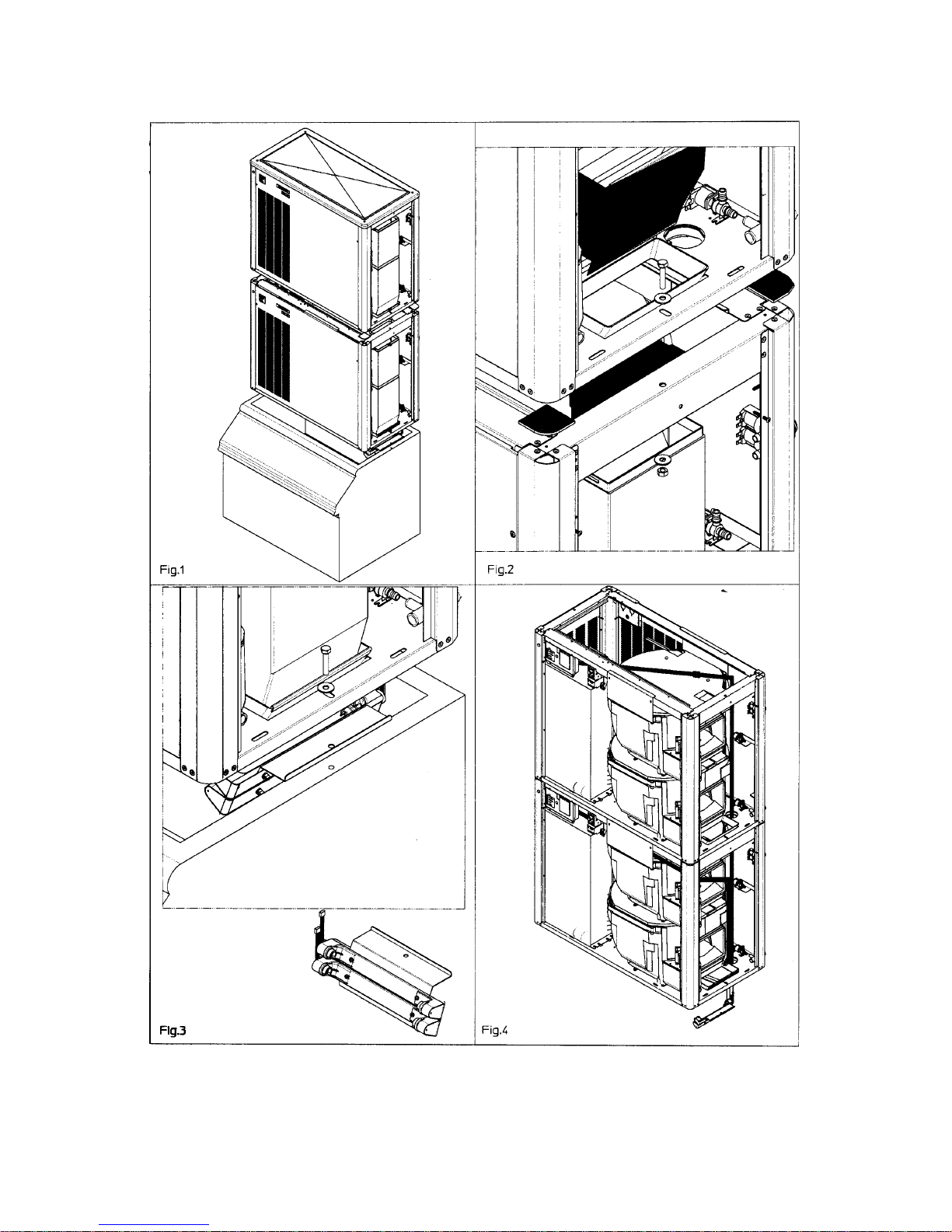
D. STACKING INSTALLATION
A Stacking Kit KSC 11 is available as an accessory
on request to allow the installation of two Modular
Cubers one on top of the other.
The Stacking Kit is consisting of:
a) unit base gasket
b) plastic reinforced ice chute
connections
Use the ice chute connections supplied in the
KSC Kits..........
... to connect the ice chute of the bottom machine
with the one of the top machine
Page 7
Page 7

Page 8
Page 8
E. ELECTRICAL CONNECTIONS
See data plate for current requirements to
determine wire size to be used for electrical
connections. All SCOTSMAN icemakers require
a solid earth wire.
All SCOTSMAN ice machines are supplied from
the factory completely pre-wired and require only
electrical power connections to the wire cord
provided at the rear of the unit.
Make sure that the ice machine is connected to
its own circuit and individually fused (see data
plate for fuse size).
The maximum allowable voltage variation should
not exceed -10% and +10% of the data plate
rating. Low voltage can cause faulty functioning
and may be responsible for serious damage to
the overload switch and motor windings.
NOTE. All external wiring should conform to
national, state and local standards and
regulations.
Check voltage on the line and the ice maker’s
data plate before connecting the unit.
F. WATER SUPPLY AND DRAIN
CONNECTIONS
General
When choosing the water supply for the ice flaker
consideration should be given to:
a) Length of run
b) Water clarity and purity
c) Adequate water supply pressure
Since water is the most important single ingredient
in producting ice you cannot emphasize too
much the three items listed above.
Low water pressure, below 1 bar may cause
malfunction of the ice maker unit.
Water containing excessive minerals will tend to
produce cloudy coloured ice cubes, plus scale
build-up on parts of the water system.
Water supply
Connect the 3/4" GAS male fitting of the solenoid
water inlet valve, using flexible tubing or a 3/8"
O.D. copper pipe, to the cold water supply line
with regular plumbing fitting and a shut-off valve
installed in an accessible position between the
water supply line and the unit.
Water supply - Water cooled models
The water cooled versions of SCOTSMAN Ice
Makers require two separate inlet water supplies,
one for the water sprayed for making the ice
cubes and the other for the water cooled
condenser.
Connect the 3/4" GAS male fitting of the water
inlet, using the flexible tubing or a 3/8" O.D.
copper pipe, to the cold water supply line with
regular plumbing fitting and a shut-off valve
installed in an accessible position between the
water supply line and the unit.
Water drain
The recommended drain tube is a plastic or
flexible tube with 18 mm (3/4") I.D. which runs to
an open trapped and vented drain. When the
drain is a long run, allow 3 cm pitch per meter
(1/4" pitch per foot).
A vent at the unit drain connection is also required
for proper sump drainage.
Water drain - Water cooled models
Connect the 3/4" GAS male fitting of the
condenser water drain, utilizing a second flexible
tubing or a 3/8" O.D. copper tubing, to the open
trapped and vented drain.
NOTE. The water supply and the water drain
must be installed to conform with the local
code. In some case a licensed plumber and/
or a plumbing permit is required.
G. FINAL CHECK LIST
1. Is the unit in a room where ambient
temperatures are within a minimum of 10°C
(50°F) even in winter months?
2. Is there at least a 15 cm (6") clearance
around the unit for proper air circulation?
3. Is the unit level? (IMPORTANT)
4. Have all the electrical and plumbing
connections been made, and is the water supply
shut-off valve open?
5. Has the voltage been tested and checked
against the data plate rating?
6. Has the water supply pressure been
checked to ensure a water pressure of at least 1
bar (14 psi).
7. Have the bolts holding the compressor down
been checked to ensure that the compressor is
snugly fitted onto the mounting pads?
8. Check all refrigerant lines and conduit lines
to guard against vibrations and possible failure.
9. Have the bin liner and cabinet been wiped
clean?
10. Has the owner/user been given the User
Manual and been instructed on the importance of
periodic maintenance checks?
11. Has the Manufacturer’s registration card
been filled in properly? Check for correct model
and serial number against the serial plate and
mail the registration card to the factory.

Page 9
Page 9
H. INSTALLATION PRACTICE
1. Hand shut-off valve
2. Water filter
3. Water supply line (flexible hose)
4. 3/4" gas male fitting
5. Power line
6. Main switch
7/9. Drain fitting
8/10. Vented drain line
11. Open trapped vented drain
WARNING. This icemaker is not designed for outdoor installation and will not function in
ambient temperatures below 10°C (50°F) or above 40°C (100°F).
This icemaker will malfunction with water temperatures below 5°C (40°F) or above 35°C
(90°F).
Page 10
Page 10
OPERATING INSTRUCTIONS
NOTE.
Ice maker pcb is equipped by jumper
cleaning reminding setting (see pag. 20)
suitable to alert users after certain time of unit
operation. This would advice for preventive
maintenance.
This time can be adjusted for 6 or 12 months
operation (upon installer advice related to
installation site water and ambient condition);
once selected time is elapsed RED front panel
lamp blinks slowly and ice maker will keep on
working anyway.
Pcb is also equipped by 3 (standard) or 60
(machines operating at 400/50/3) minutes
jumper setting start up delay (see pag. 20).
In case of pcb setting to 60 minutes ice maker
doesn't start until this time is elapsed. After
having correctly installed the ice maker and
completed the plumbing and electrical
connections, perform the following “Start-up”
procedure.
START UP
After having correctly installed the ice maker and
completed the plumbing and electrical
connections, perform the following “Start-up” procedure.
A. Give power to the unit to start it up by
switching "ON" the power line main disconnect
switch.
NOTE.
Every time the unit returns under
power, after having been switched off, the
water inlet valve, the hot gas valve and the
water drain valve get energized for a period
of 5 minutes, thus to admit new water to the
machine sump reservoir to fill it up and,
eventually, to wash-off any dirt that can have
deposited in it during the unit off period
(Fig.1).
B. During the water filling operation, check to
see that the incoming water dribbles, through the
evaporator platen dribbler holes, down into the
sump reservoir to fill it up and also that the
incoming surplus of water flows out through the
overflow pipe into the drain line.
During the water filling phase the components
energized are:
THE WATER INLET SOLENOID VALVE
THE HOT GAS SOLENOID VALVE
THE WATER DRAIN SOLENOID VALVE/S
for the first 30 seconds.
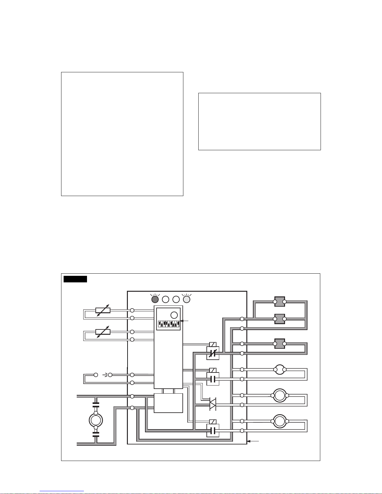
16
15
14
13
2
1
7
8
9
10
3
4
5
6
11
12
Rx Tx
WATER IN VALVE
HOT GAS VALVE
CONTACTOR COIL
FAN MOTOR
WATER PUMP
- EVAPORATOR
- AMBIENT
- CONDENSER
TEMPERATURE SENSORSBINCOMPRESSOR
TRANSF.
DATA
PROCESSOR
ELECTR.
TIMER
DIP
SWITCH
ELECTRONIC CARD
L
N
RELAYS
RELAY
TRIAC
WATER DRAIN VALVE
FIG. 1
 Loading...