

Page 1
Page 1
SERVICE MANUAL
MC 15
MC 45
R 404 A VERSION
Electronic
modular cubers
MS 1000.10 REV. 06/2003

Page 2
Page 2
TABLE OF
CONTENTS
Table of contents
Specifications MC 15
Specifications MC 45
GENERAL INFORMATION AND INSTALLATION
Introduction
Unpacking and Inspection - Ice maker
Unpacking and Inspection - Storage bin
Location and levelling
Stacking installation
Stacking installation - Mixed units
Stacking installation - Electronic units
Electrical connections
Water supply and drain connections
Final check list
Installation practice
OPERATING INSTRUCTIONS
Start up
Operatiobnal checks
OPERATING PRINCIPLES (How it works)
Freezing cycle
Harvest cycle
Control sequence
Component description
ADJUSTMENT, REMOVAL AND REPLACEMENT PROCEDURES
Adjustment of the cube size
Remplacement of evaporator temperature sensor
Remplacement of condenser temperature sensor
Remplacement of ice level light control
Remplacement of P.C. Board
Remplacement of the water pump
Remplacement of water inlet solenoid valve
Removal of the flow control
Remplacement of hot gas valve coil
Remplacement of water drain solenoid valve (Optional)
Remplacement of fan motor
Remplacement of spray bar
Remplacement of drier
Remplacement of hot gas valve body
Remplacement of evaporator platen
Remplacement of air cooled condenser
Remplacement of water cooled condenser
Replacement of water regulating valve (water cooled models)
Replacement of compressor
Wiring diagram
Service diagnosis
MAINTENANCE AND CLEANING INSTRUCTIONS
General
Icemaker
Cleaning instructions of water system
2
3
5
18
20
21
22
26
27
27
27
27
27
27
27
27
28
28
28
28
28
29
29
29
29
30
31
35
37
37
38
13
14
7
7
7
8
8
8
10
11
11
11
12
Page 3
Page 3
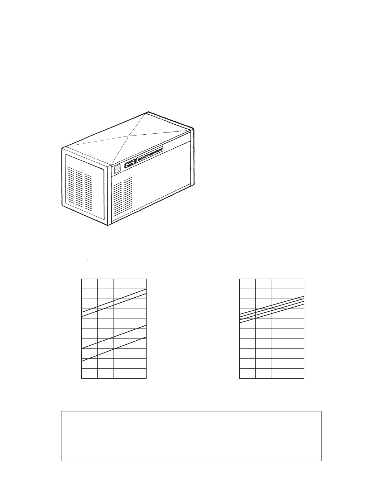
SPECIFICATIONS
ELECTRONIC MODULAR CUBER MODEL MC 15
I
mportant operating requirements:
MIN.
Air temperature 10°C (50°F)
Water temperature 5°C (40°C)
Water pressure 1 bar (14 psi)
Electr. voltage variations
from voltage rating
specified on nameplate -10%
180
170
160
150
140
130
120
110
100
90
80
Kg.
32
10 °C27 21 15
MODÈLES REFROIDIS PAR AIR
TEMPÉRATURE DE L'EAU
TEMPÉRATURE AMBIANTE
PRODUCTION DE GLACE EN 24 H
32
38
10
21
°C
180
170
160
150
140
130
120
110
100
90
80
Kg.
32
10 °C27 21 15
MODÈLES REFROIDIS PAR EAU
TEMPÉRATURE DE L'EAU
TEMPÉRATURE AMBIANTE
PRODUCTION DE GLACE EN 24 H
10
21
32
38
°C
ice making capacity
MAX.
40°C (100°F)
35°C (90°F)
5 bars (70 psi)
+10%
NOTE. The daily ice-making capacity is directly related to the condenser air inlet temperature, water
temperature and age of the machine.
To keep your SCOTSMAN MODULAR CUBER at peak performance levels, periodic maintenance
checks must be carried out as indicated on page 37 of this manual.
Production charts shown are indicating the production of MCM and MCL models. For MCS models
ice production is approx. 10% lower.
AIR COOLED MODELS
AMBIENT TEMPERATURE
WATER TEMPERATURE
ICE PRODUCED PER 24 HRS
AIR COOLED MODELS
AMBIENT TEMPERATURE
WATER TEMPERATURE
ICE PRODUCED PER 24 HRS
WATER COOLED MODELS
Page 4
Page 4
1.5
MC 15 AS 6B Air Stainless steel
MC 15 WS 6B Water Stainless steel
Model Cond. unit Finish Comp. HP Water req. - lt/24 HR
SPECIFICATIONS
300
1700*
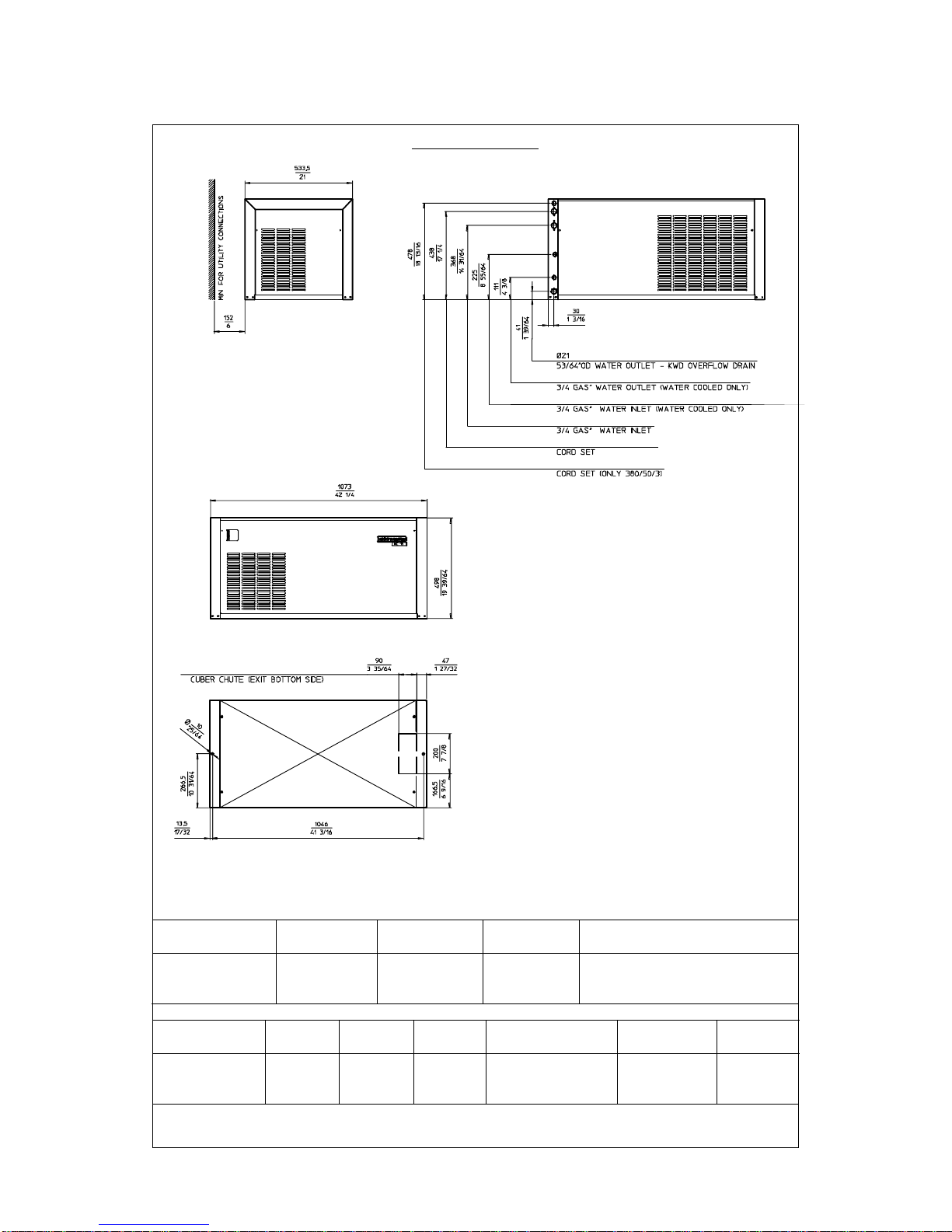
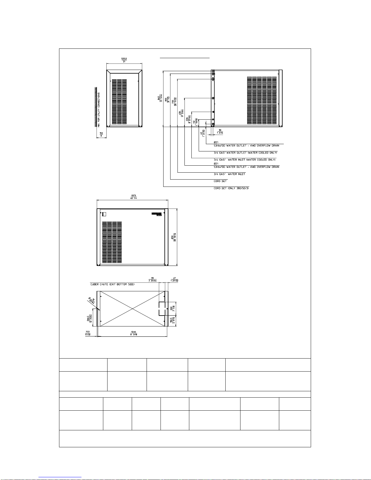
MC 15 - MACHINE SPECIFICATIONS
DIMENSIONS:
HEIGHT 499 mm.
WIDTH 1073 mm.
DEPTH 534 mm.
WEIGHT 117 Kgs.
ACCESSORIES
KSC 11: Cube stacking kit
220-230/50/1 7 1250 25.7 3 x
Starts Electric power cons.
amps. Kwh x 24 HR
Basic electr. Amps Watts N. of wires Amps. fuse
230/50/1N 5.5 32 3 x 1.5 m/m
2
20
400/50/3N 5 x 1.5 m/m
2
10
Cubes per harvest: MCL-15 72 large - MCM-15 102 medium - MCS 15 198 small
* At 15°C (60°F) water temperature
Page 5
Page 5
310
300
290
280
270
260
250
240
230
220
210
200
190
180
Kg.
32
10 °C27 21 15
MODÈLES REFROIDIS PAR AIR
TEMPÉRATURE DE L'EAU
TEMPÉRATURE AMBIANTE
PRODUCTION DE GLACE EN 24 H
32
38
10
21
°C
MODÈLES REFROIDIS PAR EAU
310
300
290
280
270
260
250
240
230
220
210
200
190
180
Kg.
32
10 °C27 21 15
TEMPÉRATURE DE L'EAU
TEMPÉRATURE AMBIANTE
PRODUCTION DE GLACE EN 24 H
10
21
32
38
°C
ice making capacity
AIR COOLED MODELS
AMBIENT TEMPERATURE
WATER TEMPERATURE
ICE PRODUCED PER 24 HRS
AMBIENT TEMPERATURE
WATER TEMPERATURE
ICE PRODUCED PER 24 HRS
WATER COOLED MODELS
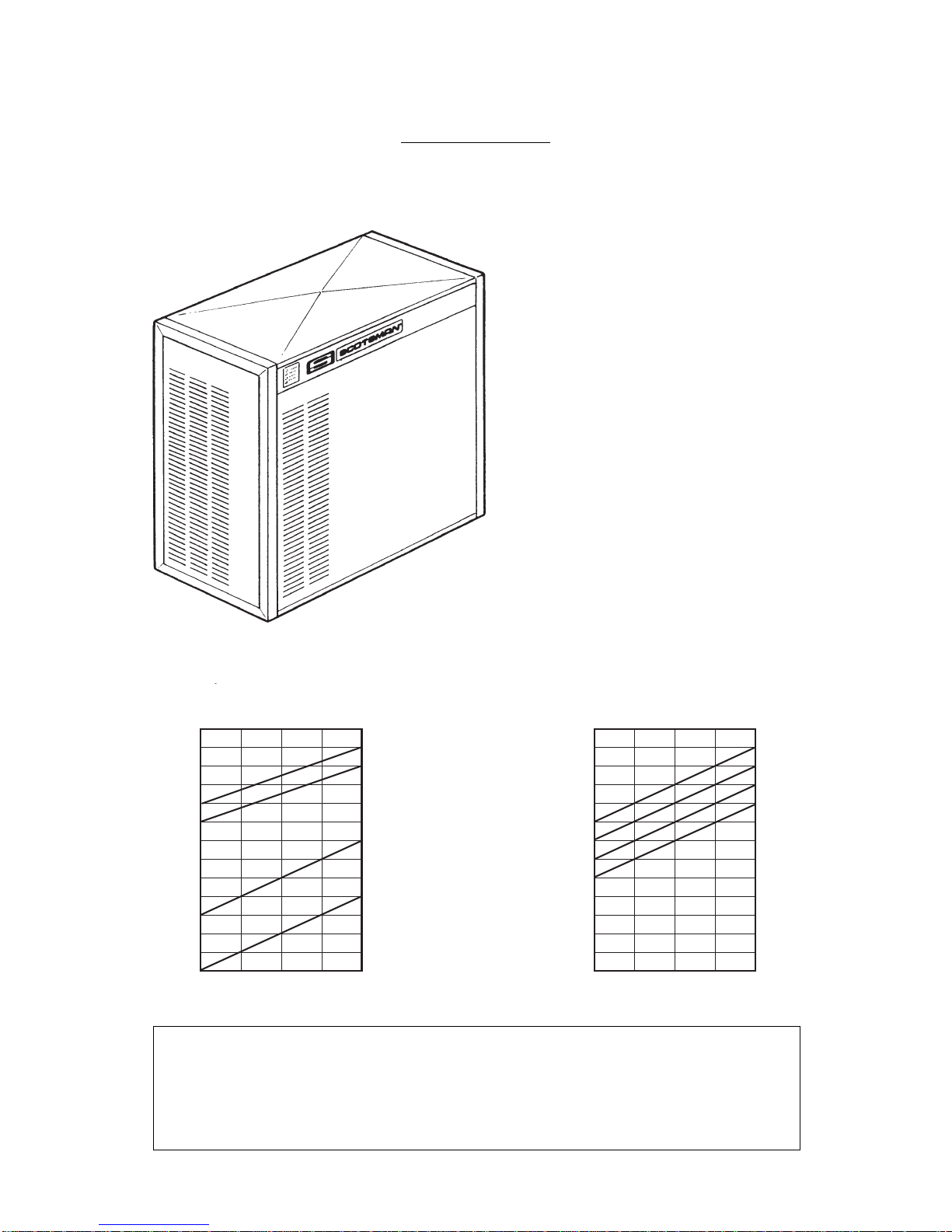
SPECIFICATIONS
ELECTRONIC CUBER MODEL MC 45
I
mportant operating requirements:
MIN.
Air temperature 10°C (50°F)
Water temperature 5°C (40°C)
Water pressure 1 bar (14 psi)
Electr. voltage variations
from voltage rating
specified on nameplate -10%
MAX.
40°C (100°F)
35°C (90°F)
5 bars (70 psi)
+10%
NOTE. The daily ice-making capacity is directly related to the condenser air inlet temperature, water
temperature and age of the machine.
To keep your SCOTSMAN MODULAR CUBER at peak performance levels, periodic maintenance
checks must be carried out as indicated on page 37 of this manual.
Production charts shown are indicating the production of MCM and MCL models. For MCS models
ice production is approx. 10% lower.
Page 6
Page 6
MC 45 AS 6B Air Stainless steel
MC 45 WS 6B Water Stainless steel
2.5
Model Cond. unit Finish Comp. HP Water req. - lt/24 HR
SPECIFICATIONS
660
2800*
MC 45 - MACHINE SPECIFICATIONS
DIMENSIONS:
HEIGHT 860 mm.
WIDTH 1073 mm.
DEPTH 554 mm.
WEIGHT 185 Kgs.
ACCESSORIES
KSC 11: Cube stacking kit
220-230/50/1 7 2400 50 3 x
Basic electr. Amps Watts N. of wires Amps. fuse
230/50/1N 10 66 3 x 1.5 m/m
2
20
400/50/3N 5.5 14 5 x 1.5 m/m
2
10
Starts Electric power cons.
amps. Kwh x 24 HR
Cubes per harvest: MCL-45 144 large - MCM-45 204 medium - MCS 45 396 small
* At 15°C (60°F) water temperature

Page 7
Page 7
A. INTRODUCTION
This manual provides the specifications and the
step-by-step procedures for the installation, startup and operation, maintenance and cleaning for
the SCOTSMAN MODULAR CUBERS.
The Electronic Modular Cubers are quality
designed, engineered and manufactured.
Their ice making systems are thoroughly tested
providing the utmost in flexibility to fit the needs
of a particular user.
These icemakers have been engineered to our
own rigid safety and performence standards.
NOTE. To retain the safety and performance
built into this icemaker, it is important that
installation and maintenance be conducted
in the manner outlined in this manual.
Storage Bin
Since the MC series Modular Cubers do not
have their own attached ice storage bins, it is
necessary to use an auxiliary bin such as the Bin
B 350 or B 550.
B. UNPACKING AND INSPECTION
Modular Cuber
1. Call your authorized SCOTSMAN Distributor
or Dealer for proper installation.
2. Visually inspect the exterior of the packing
and skid. Any severe damage noted should be
reported to the delivering carrier and a concealed
damage claim form filled in subjet to inspection
of the contents with the carrier’s representative
present.
3. a) Cut and remove the plastic strip securing
the carton box to the skid.
b) Remove the packing nails securing the
carton box to the skid.
c) Cut open the top of the carton and remove
the polystyre protection sheet.
d) Pull out the polystyre posts from the
corners and then remove the carton.
4. Remove top and sides panels of the unit
and inspect for any concealed damage. Notify
carrier of your claim for the concealed damage
as stated in step 2 above.
GENERAL INFORMATION AND INSTALLATION
5. Loose two nuts on left and rights side of the
unit base and remove it from the skid. Save the
two bolts and nuts to mount the machine on
storage bin or on top of another Modular Cuber.
6. Remove all internal support packing and
masking tape and the hardware package.
7. Check that refrigerant lines do not rub
against or touch other lines or surfaces, and that
the fan blade moveS freely.
8. Check that the compressor fits snugly onto
all its mounting pads.
9. See data plate on the rear side of the unit
and check that local main voltage corresponds
with the voltage specified on it.
CAUTION. Incorrect voltage supplied to
the icemaker will void your parts
replacement program.
10. Remove the manufacturer’s registration
card from the inside of the User Manual and fillin all parts including: Model and Serial Number
taken from the data plate.
Forward the completed self-addressed
registration card to Frimont/Scotsman Europe
factory.
Storage bin
1. Follow the steps 1, 2 and 3 above to unpack
the storage bin.
2. Unloose the two bolts and remove the
protec
tion plate from the drain fitting.
3. Carefully lay it down on its rear side and fit
the four legs into their sockets.
4. Remove all internal support packing and
masking tape as well as the plastic ice cube
deflector.
5. Remove the manufacturer’s registration
card from the inside of the User Manual and fillin all parts including: Model and Serial Number
taken from the data plate.
Forward the completed self-addressed
registration card to Frimont/Scotsman Europe
factory.

Page 8
Page 8
C. LOCATION AND LEVELLING
WARNING. This Ice Cuber is designed for
indoor installation only. Extended periods
of operation at temperature exceeding
the following limitations will constitute
misuse under the terms of the SCOTSMAN
Manufacturer’s Limited Warranty resulting
in LOSS of warranty coverage.
1. Position the Bin in the selected permanent
location.
Criteria for selection of location include:
a) Minimum room temperature 10°C (50°F)
and maximum room temperature 40°C (100°F).
b) Water inlet temperatures: minimum 5°C
(40°F) and maximum 35°C (90°F).
c) Well ventilated location for air cooled
models.
d) Service access: adequate space must be
left for all service connections through the rear of
the ice maker. A minimum clearance of 15 cm
(6") must be left at the sides of the unit for routing
cooling air drawn into and exhausted out of the
compartment to maintain proper condensing
operation of air cooled models.
2. Level the Storage Bin Assy in both the left
to right and front to rear directions by means of
the adjustable legs.
3. Inspect the Storage Bin top mounting gasket
which should be flat with no wrinkles, to provide
a good sealing when the Modular Cuber is
installed on top of it.
4. Place the Modular Cuber on top of Storage
bin using care not to wrinkle or tear the gasket.
5. Lift a little bit the Modular Cuber right side in
order to be able to mount the ice level control
bracket taking care to align the hole located on
unit base to mate with the one on the top of the
Bin.
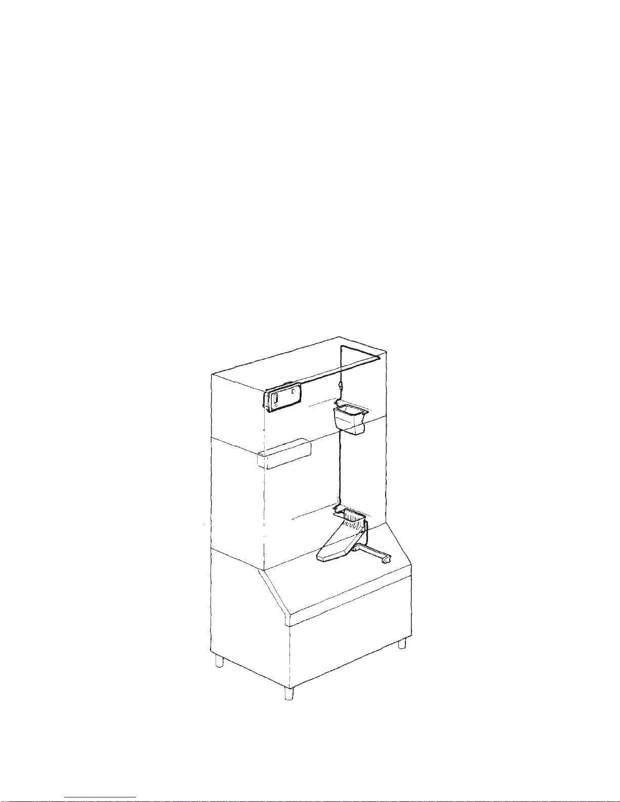
6. Remove the PVC plastic plug closing the
round hole located on the right side of the ice
chute opening.
7. Trace the ice level control assy, secured for
the transport on top of the evaporator of the
Modular Cuber, and direct it down through the
round hole into the Storage Bin.
8. Fasten the ice level control assy on its
bracket by means of the two screws found in the
hardware package supplied with the unit.
9. Make a cut (shear) in the PVC plastic plug
that goes from its edge to the center; insert the
ice level control cable in the center of the plastic
plug so to prevent it from any sort of contact with
the unit frame, then place again the PVC plug in
the round hole keeping the cable exceeding
portion inside the unit.
10. Install the plastic ice cube deflector by
hooking it on the flange of the ice chute opening
in unit base (see illustration).
11. Secure the Modular Cuber on the top of the
Storage Bin using the two bolts and diber washer
found in the hardware package supplied with the
unit.
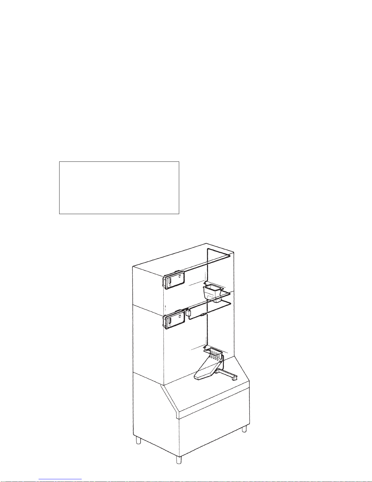
D. ISTACKING INSTALLATION
A Stacking Kit KSC 11 is available as an
accessory on request to allow the installation of
two Modular Cubers one on top of the other.
The Stacking Kit is consisting of:
a) a plastic reinforced Ice Chute Connection
b) an Interface P.C. Board
c) an Extension Cable
d) an adhesive Rubber Stripe
enabling to cover any stacking installation
combination as:
a) When stacking an Electronic Modular
Cuber on an Electromechanical type (Earlier
series).
b) When stacking two Electronic Modular
Cubers.
Mixed units installation
1. Unloose the four screws and remove the
top panel.
2. Remove the two plastic plugs from the
upper edges of the two side frames of the bottom
unit.
3. Trace and remove from the top of the
evaporator of Electronic Cuber the metal bracket
used to secure the ice level control assy inside
the storage bin.
4. Lift a little bit the Modular Cuber right side
in order to be able to mount the ice level control
bracket taking care to align the hole located on
unit base to mate with the one on the top of the
Bin.
Page 9
Page 9
then to pass through the round hole provided into
the base of the Electronic Modular Cuber (Upper
unit).
10. Connect the electric plug of the ice level
control cable to the Cable Extension, then plugin this one into its P.C. BOARD socket.
11. Rotate the TRIMMER setting screw located
in the front of P.C. BOARD clockwise, to its
maximum power, so to compensate the greater
resistence caused by the addition of the Cable
Extension.
12. Stick, with accuracy, the rubber stripe onto
the upper edge of the front panel of the lower unit
in order to fill the air gap between the two
machines.
13. Place again in their position the two ice
chutes and finally re-fit all the service panels
previously removed.
5. Put the Electronic Modular cuber on top of
the Electromechanical unit securing them by
means of the bolts and nuts found in the hardware
package supplied with the machine.
6. Remove the ice chute from both the unit and
insert, through the ice discharge opening of the
upper unit, the plastic reinforced Ice Chute
Connection.
7. Disconnect the ice level control terminal
plug from the P.C. BOARD of Electronic Modular
Cuber.
8. Install and fasten the ice level control assy
on its bracket by means of the two screws found
in the hardware package supplied with the unit.
9. Direct ice level control cable first to pass
through the ice discharge opening of the bottom
machine with the protective sheath correctly
located in correspondance of this opening and
Page 10
Page 10
5. Disconnect the ice level control terminal
plug from the P.C. Board of the upper Electronic
Modular Cuber (now colled secondary).
6. Secure the interface P.C. Board to the
contactor metal bracket of the lower unit (now
called primary) by means of the supplied plastic
clamp.
7. Disconnect the ice level control terminal
plug from the P.C. Board of the primary unit and
connect it to the INLET socket of the interface
P.C. Board (shorter wire).
8. Connect the primary OUTLET terminal
plug of the Interface P.C. Board (wire of medium
lenght) to the P.C. Board socket of the primary
unit.
9. Connect the secondary OUTLET plug
(longer wire) of the interface P.C. Board to the
P.C. Board socket of the secondary unit (see
drawing).
10. Turn the TRIMMER setting screw (located
on the front center of P.C. Board) of the ice level
control of the secondary unit clockwise to its
maximum power (Only on Syen type).
Electronic units installation
1. Unloose the four screws and remove the
top panel.
2. Remove the two plastic plugs from the
upper edges of the two side frames of the bottom
unit.
3. Put the second Electronic Modular Cuber
onto the bottom one and after having alignet the
two cabinets secure them by means of the bolts
and nuts founded in the hardware package
supplied with the machine.
4. Remove the ice chute from both the unit
and insert, through the ice discharge opening of
the upper unit, the plastic reinforced Ice Chute
Connection.
ATTENTION. All the two PC Boards
installed on the two machines as well as
the interface PC Board supplied in the
KSC 11 Kit must be of the same supplier
(Syen or Pro.EI.Ind.).
If not the unit with the different one remains
OFF at storage bin full.

Page 11
Page 11
Since water is the most important single ingredient
in producting ice you cannot emphasize too
much the three items listed above.
Low water pressure, below 1 bar may cause
malfunction of the ice maker unit.
Water containing excessive minerals will tend to
produce cloudy coloured ice cubes, plus scale
build-up on parts of the water system.
Water supply
Connect the 3/4" GAS male fitting of the solenoid
water inlet valve, using flexible tubing or a 3/8"
O.D. copper pipe, to the cold water supply line
with regular plumbing fitting and a shut-off valve
installed in an accessible position between the
water supply line and the unit.
Water supply - Water cooled models
The water cooled versions of SCOTSMAN Ice
Makers require two separate inlet water supplies,
one for the water sprayed for making the ice
cubes and the other for the water cooled
condenser.
Connect the 3/4" GAS male fitting of the water
inlet, using the flexible tubing or a 3/8" O.D.
copper pipe, to the cold water supply line with
regular plumbing fitting and a shut-off valve
installed in an accessible position between the
water supply line and the unit.
Water drain
The recommended drain tube is a plastic or
flexible tube with 18 mm (3/4") I.D. which runs to
an open trapped and vented drain. When the
drain is a long run, allow 3 cm pitch per meter
(1/4" pitch per foot).
A vent at the unit drain connection is also required
for proper sump drainage;
Water drain - Water cooled models
Connect the 3/4" GAS male fitting of the
condenser water drain, utilizing a second flexible
tubing or a 3/8" O.D. copper tubing, to the open
trapped and vented drain.
NOTE. The water supply and the water drain
must be installed to conform with the local
code. In some case a licensed plumber and/
or a plumbing permit is required.
F. FINAL CHECK LIST
1. Is the unit in a room where ambient
temperatures are within a minimum of 10°C
(50°F) even in winter months?
2. Is there at least a 15 cm (6") clearance
around the unit for proper air circulation?
3. Is the unit level? (IMPORTANT)
11. The interface P.C. Board is now ready to
stop simultaneously the operation of the two
units when the infrared beam of the ice level
control is interrupted by the stored ice cubes.
ATTENTION. After removal of the ice
cubes both units resume their operation
starting from the beginning of freezing
cycle.
During the first freezing cycle it could be
posible that the ice cubes produced by
one of the two ice makers be not of correct
shape (cloudy and shallow) due to an
insufficient water level in its sump tank.
This minor problem will desappear in the
next batch because in the harvest cycle
the sump tank will be properly filled-up.
12. Stick, with accuracy, the rubber stripe onto
the upper edge of the front panel of the lower unit
in order to fill the air gap between the two
machines.
13. Place again in their position the two ice
chutes and finally re-fit the service panels
previously removed.
E. ELECTRICAL CONNECTIONS
See data plate for current requirements to
determine wire size to be used for electrical
connections. All SCOTSMAN icemakers require
a solid earth wire.
All SCOTSMAN ice machines are supplied from
the factory completely pre-wired and require only
electrical power connections to the wire cord
provided at the rear of the unit.
Make sure that the ice machine is connected to
its own circuit and individually fused (see data
plate for fuse size).
The maximum allowable voltage variation should
not exceed -10% and +10% of the data plate
rating. Low voltage can cause faulty functioning
and may be responsible for serious damage to
the overload switch and motor windings.
NOTE. All external wiring should conform to
national, state and local standards and
regulations.
Check voltage on the line and the ice maker’s
data plate before connecting the unit.
E. WATER SUPPLY AND DRAIN
CONNECTIONS
General
When choosing the water supply for the ice flaker
consideration should be given to:
a) Length of run
b) Water clarity and purity
c) Adequate water supply pressure
Page 12
Page 12
4. Have all the electrical and plumbing
connections been made, and is the water supply
shut-off valve open?
5. Has the voltage been tested and checked
against the data plate rating?
6. Has the water supply pressure been
checked to ensure a water pressure of at least 1
bar (14 psi).
7. Have the bolts holding the compressor down
been checked to ensure that the compressor is
snugly fitted onto the mounting pads?
8. Check all refrigerant lines and conduit lines
to guard against vibrations and possible failure.
9. Have the bin liner and cabinet been wiped
clean?
10. Has the owner/user been given the User
Manual and been instructed on the importance
of periodic maintenance checks?
11. Has the Manufacturer’s registration card
been filled in properly? Check for correct model
and serial number against the serial plate and
mail the registration card to the factory.
12. Has the owner been given the name and
the phone number of the authorized SCOTSMAN
Service Agency serving him?
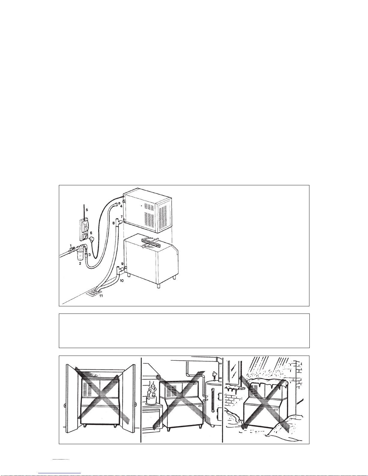
G. INSTALLATION PRACTICE
1. Hand shut-off valve
2. Water filter
3. Water supply line (flexible hose)
4. 3/4" gas male fitting
5. Power line
6. Main switch
7/9. Drain fitting
8/10. Vented drain line
11. Open trapped vented drain
WARNING. This icemaker is not designed for outdoor installation and will not function in
ambient temperatures below 10°C (50°F) or above 40°C (100°F).
This icemaker will malfunction with water temperatures below 5°C (40°F) or above 35°C
(90°F).
 Loading...