


Page 1
Page 1
09014400
Scotsman Ice Srl
Via Lainate, 31 - 20010 Pogliano M.se - Milano - Italy
Tel. +39-02-93960.1 (Aut. Sel.)- Telefax +39-02-93550500
Direct Line to Service & Parts:
Phone +39-02-93960350 - Fax +39-02-93540449
Website: www.scotsman-ice.it
E-Mail: scotsman.europe@scotsman.it
ISO 9001 - Cert. n. 0080
SERVICE MANUAL
MAR 78
MAR 108
MAR 128
MAR 208
MAR 308
SPLIT
RN
090144 00 - REV. 03/2016

Page 2
Page 2
FOREWORD
SCOTSMAN MAR SPLIT UNITS are available in
five basic models MAR 78, MAR 108, MAR 128,
MAR 208 and MAR 308 operating by fresh water.
MAR 78, MAR 128 and MAR 308 only are available,
upon request, presetted to operate by sea water.
They come complete with a stainless steel cabinet,
with a drive motor at V. 230/50/3 or 400/50/3-N
Volt, with expansion valve, heat exchanger, float
reservoir, time delay switch, bin thermostat, water
pump, ice spout switch, liquid solenoid valve,
water pressure control evaporator pressure ctl.
valve.
The refrigerating and electrical system must be
completed by the purchaser as per the instructions
given in this service manual who has to provide
for the complete condensing unit, its controls and
refrigerant tubings.
We suggest to take time now to read this manual
which contains a lot of valuable informations on
the MAR Split System.
For any further queries regarding the care or
operation of the machine, please contact:
ICE SYSTEMS
®
SCOTSMAN - EUROPE - FRIMONT SPA
Via Puccini, 22 - 20010 Bettolino di Pogliano (Milano) Italy
Tel. +39-02-93960.1 (Aut. Sel.)- Telefax +39-02-93550500
Direct Line to Service & Parts:
Phone +39-0331-589305 - Fax +39-0331-584306
Website: www.scotsman-ice.com
E-Mail: scotsman.europe@frimont.inet.it
®

Page 3
Page 3
TABLE OF
CONTENTS
Foreword page 2
Table of contents 3
Specifications 4-9
Section I GENERAL INFORMATION
General 10
Application area 10
Condensing unit 10
Control devices 11
Location considerations 12
Refrigerant lines 12
Hydraulic circuit 12
Ice storage room 12-14
Unit layout 15
Section II INSTALLATION
Unpacking and inspection 16
Location and levelling 16
Refrigerant piping connections 16
Water piping connections 17
Water and refrigerant circuit 17
Electrical connections 18
Installation practice 19
Mar Split in multiple installation 20
Typical non-code commercial installation 20
Section III TESTING
Complete system leak test 21
Complete system evacuation 21
Complete system charging 21
Start-up & Check-out 21
Operational check-out 21-23
Section IV PRINCIPLE OF OPERATION - HOW IT WORKS
ICE maker 24
MAR Split electrical/refrigeration 25-26
Section V ADJUSTMENT & REMOVAL & REPLACEMENT
PROCEDURES
MAR Split 27-28
Section VI MAINTENANCE & CLEANING INSTRUCTIONS 29-32
Section VII SERVICE DIAGNOSIS 33-34
Section VIII WIRING DIAGRAMS 35
Page 4
Page 4
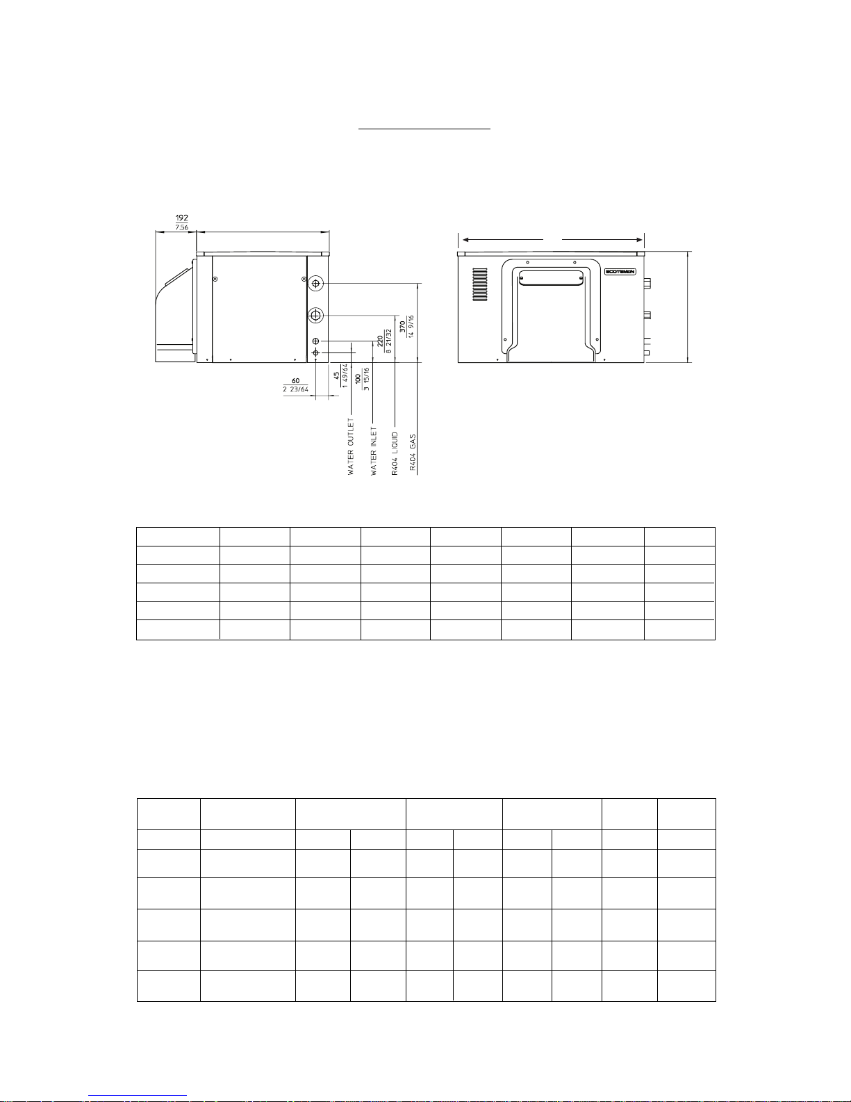
SPECIFICATIONS
MAR 78 - 108 - 128 - 208 - 308
A
B
C
Ø 1
Ø 2
Ø 3
Ø 4
(*) "THICK ICE" SETTING - AT 10°/10°C (ambient/water temp.)
TECHNICAL SPECIFICATION
SPLIT
MODEL
Basic
Electricals
Ice Production (*)
Kg/24 Hr.
Drive Motor
Finish
Shipping
Weight
V
Sea water Fresh W. Kcal/Hr Hp Amp
kg
MAR 78
400/50/3 - N
230/50/3
510
3200 1/2
SS
MAR 108
400/50/3 - N
230/50/3
670 4800 1/2
1.2
2.1
SS
MAR 128
400/50/3 - N
230/50/3
1000 6000 1/2
1.2
2.1
SS
MAR 208
400/50/3 - N
230/50/3
1650 8250 1/2
1.2
2.1
SS
MAR 308
400/50/3 - N
230/50/3
2200 9700 1/2
1.2
2.1
SS
131
131
131
223
223
****
****
850
****
Cooling req.ts
1800
Evap.T.°C
-18
-24
-24
-20
-30
1.2
2.1
A B C Ø1Ø2Ø3Ø4
MAR 78 621 876 520 3/4" gas 3/8" gas 3/4" gas 21 mm
MAR 108 621 876 520 3/4" gas 3/8" gas 3/4" gas 21 mm
MAR 128 621 876 520 3/4" gas 3/8" gas 3/4" gas 21 mm
MAR 208 661 1297 520 3/4" gas 1/2" gas 28 mm 21 mm
MAR 308 661 1297 520 3/4" gas 1/2" gas 28 mm 21 mm
Ø1
= GAS LINE CONNECTION (SUCTION)
Ø3
= WATER INLET FITTING
Ø2
= LIQUID LINE CONNECTION
Ø4
= WATER OUTLET CONNECTION
Page 5
Page 5
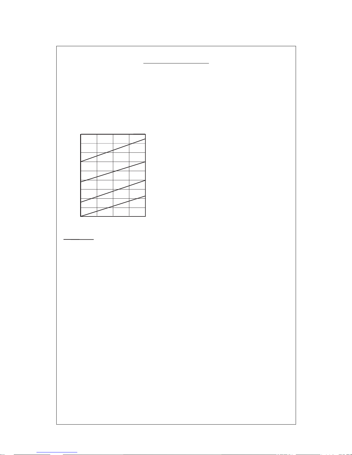
MAR 78 SPLIT
Set for Fresh water Operation
ICE MAKING CAPACITY
IMPORTANT OPERATING REQUIREMENTS:
WATER LEVEL IN DRUM RESERVOIR 115-120 mm
WITH WATER PUMP / SPRAY BAR
DRUM ROTATING SPEED 1.1 RPM (thick ice)
CONDENSING CAPACITY 4900 Kcal/hr (TD 10 ÷ 15 °C)
HEAD PRESSURE SETTING 15 ÷ 17 Bar on air cooled units
17 Bar on water cooled unit
LOW PRESSURE SETTING 2.2 Bar on air cooled units
1.8 Bar on water cooled units
HI-PRESSURE CONTROL SETTING 34 ± 2 Bar A/C
30 ± 2 Bar W/C
LO-PRESSURE CONTROL SETTING 0.2 Bar
WATER PRESSURE CONTROL SETTING 0.8 Bar
MAX. WATER TEMPERATURE 35 °C
MIN. WATER TEMPERATURE 5 °C
MIN. WATER PRESSURE 1 atm.
MAX. WATER PRESSURE 5 atm.
MIN. AMBIENT TEMPERATURE 5 °C
MAX. AMBIENT TEMPERATURE 40 °C
MAX. VOLTAGE VARIATION ± 10%
NOTE. The production diagrams herebelow represented can be used as reference, since the data
indicated have been obtained with a air/water cooled condensing unit equipped with a hermetic
compressor type U.H. TFH 2480Z providing - 3200 Kcal/hr at -18 °C Refrigerating capacity.
520
500
480
460
440
420
400
380
360
340
Kg./24 h
°C
32 27
21
15
°C
10
21
32
38
o
AIR COOLED MODELS
WA TER TEMPERATURE
AMBIENT TEMPERATURE
ICE PRODUCED PER 24 HRS.
10
Thicker scale ice

Page 6
Page 6
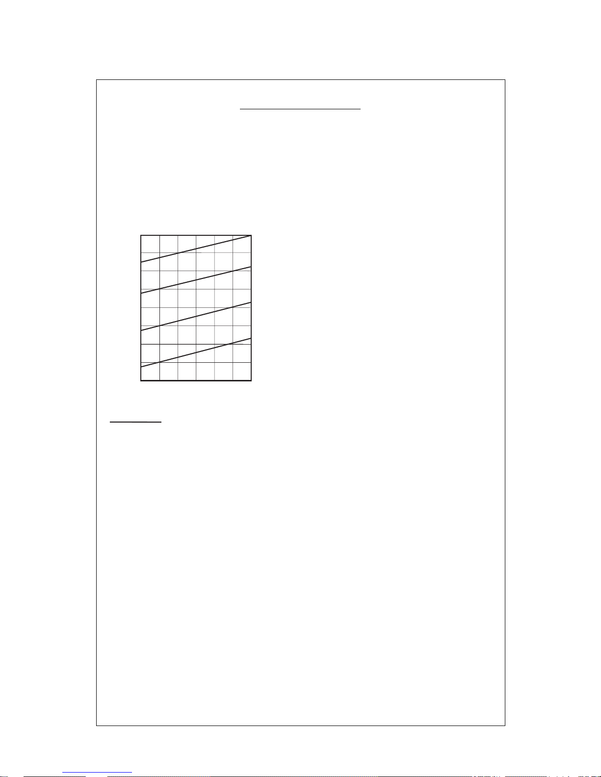
MAR 108 SPLIT
Set for Fresh water Operation
ICE MAKING CAPACITY
IMPORTANT OPERATING REQUIREMENTS:
WATER LEVEL IN DRUM RESERVOIR 115-120 mm
WITH WATER PUMP / SPRAY BAR
DRUM ROTATING SPEED 1.5 RPM (thick ice)
2.3 RPM (thin ice)
CONDENSING CAPACITY 7500 Kcal/hr (TD 10 ÷ 15 °C)
HEAD PRESSURE SETTING 15 Bar on air cooled units
15 Bar on water cooled unit
LOW PRESSURE SETTING 1.6 Bar on air cooled units
HI-PRESSURE CONTROL SETTING 36 Bar
LO-PRESSURE CONTROL SETTING 0.2 Bar
WATER PRESSURE CONTROL SETTING 0.8 Bar
MAX. WATER TEMPERATURE 35 °C
MIN. WATER TEMPERATURE 5 °C
MIN. WATER PRESSURE 1 atm.
MAX. WATER PRESSURE 5 atm.
MIN. AMBIENT TEMPERATURE 5 °C
MAX. AMBIENT TEMPERATURE 40 °C
MAX. VOLTAGE VARIATION ± 10%
NOTE. The production diagrams herebelow represented can be used as reference, since the data
indicated have been obtained with a air/water cooled condensing unit equipped with a hermetic
compressor type U.H. TAG 2516Z providing - 4800 Kcal/hr at -24 °C Refrigerating capacity.
750
700
650
600
550
500
450
Kg./24 h
°C
32 27
21
15
°C
10
21
32
38
o
AIR COOLED MODELS
WA TER TEMPERATURE
AMBIENT TEMPERATURE
ICE PRODUCED PER 24 HRS.
10
Thicker scale ice
Page 7
Page 7
MAR 128 SPLIT
Set for Fresh water Operation
ICE MAKING CAPACITY
NOTE. The production diagrams herebelow represented can be used as reference, since the data
indicated have been obtained with a air/water cooled condensing unit equipped with a hermetic
compressor type U.H. TAG 2522Z providing - 6000 Kcal/hr at -24°C Refrigerating capacity.
IMPORTANT OPERATING REQUIREMENTS:
WATER LEVEL IN DRUM RESERVOIR 115-120 mm
WITH WATER PUMP / SPRAY BAR
DRUM ROTATING SPEED 2.4 RPM (thick ice)
CONDENSING CAPACITY 9750 Kcal/hr (TD 10 ÷ 15 °C)
HEAD PRESSURE SETTING 14 ÷ 16 Bar on air cooled units
LOW PRESSURE SETTING 1.6 Bar on air cooled units
HI-PRESSURE CONTROL SETTING 36 Bar
LO-PRESSURE CONTROL SETTING 0.2 Bar
WATER PRESSURE CONTROL SETTING 0.8 Bar
MAX. WATER TEMPERATURE 35 °C
MIN. WATER TEMPERATURE 5 °C
MIN. WATER PRESSURE 1 atm.
MAX. WATER PRESSURE 5 atm.
MIN. AMBIENT TEMPERATURE 5 °C
MAX. AMBIENT TEMPERATURE 40 °C
MAX. VOLTAGE VARIATION ± 10%
1000
950
900
850
800
750
700
650
600
38
°C
32 27
21
15
AIR COOLED UNITS
WA TER TEMPERATURE
AMBIENT TEMPERATURE
ICE PRODUCED PER 24 HRS.
32
38
10 5
10
21
Thicker scale ice
Page 8
Page 8
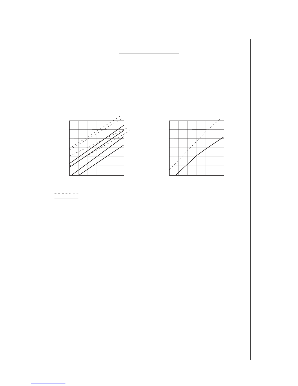
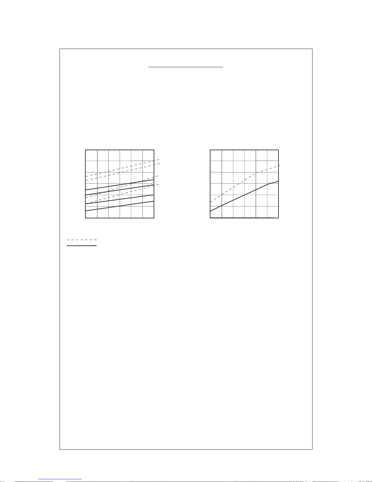
MAR 208 SPLIT
Set for Fresh water Operation
ICE MAKING CAPACITY
NOTE. The production diagrams herebelow represented can be used as reference, since the data
indicated have been obtained with a air/water cooled condensing unit equipped with a hermetic
compressor type DORIN K500 CS providing - 8250 Kcal/hr at -20 °C Refrigerating capacity.
IMPORTANT OPERATING REQUIREMENTS:
WATER LEVEL IN DRUM RESERVOIR 90-95 mm
WITH WATER PUMP / SPRAY BAR
DRUM ROTATING SPEED 1.05 RPM (thick ice)
1.60 RPM (thin ice)
CONDENSING CAPACITY 11000 Kcal/hr (TD 10 ÷ 15 °C)
HEAD PRESSURE SETTING 16 ÷ 18 Bar on air cooled units
16 ÷ 17 Bar on water cooled unit
LOW PRESSURE SETTING 1.9 Bar
HI-PRESSURE CONTROL SETTING 36 Bar
LO-PRESSURE CONTROL SETTING 0.2 Bar
WATER PRESSURE CONTROL SETTING 0.8 Bar
MAX. WATER TEMPERATURE 35 °C
MIN. WATER TEMPERATURE 5 °C
MIN. WATER PRESSURE 1 atm.
MAX. WATER PRESSURE 5 atm.
MIN. AMBIENT TEMPERATURE 5 °C
MAX. AMBIENT TEMPERATURE 40 °C
MAX. VOLTAGE VARIATION ± 10%
1700
1600
1500
1400
1300
1200
1100
Kg.
38
°C
32 27
21
15
°C
32
38
AIR COOLED UNITS
WA TER TEMPERATURE
AMBIENT TEMPERATURE
ICE PRODUCED PER 24 HRS.
32
38
WATER COOLED UNITS
10 5
10
21
1900
1800
1700
1600
1500
1400
1300
Kg.
38
°C
32 27
21
15
°C
DE 10 A' 38
o
WA TER TEMPERATURE
AMBIENT TEMPERATURE
ICE PRODUCED PER 24 HRS.
10 5
10
21
Thicker scale ice
Thiner scale ice
Page 9
Page 9
MAR 308 SPLIT
Set for Fresh water Operation
ICE MAKING CAPACITY
NOTE. The production diagrams herebelow represented can be used as reference, since the data
indicated have been obtained with a air/water cooled condensing unit equipped with a semihermetic
compressor type DORIN K1000 CS providing - 9700 Kcal/hr at -30 °C Refrigerating capacity.
IMPORTANT OPERATING REQUIREMENTS:
WATER LEVEL IN DRUM RESERVOIR 90 mm
WITH WATER PUMP / SPRAY BAR
DRUM ROTATING SPEED 1.6 RPM (thick ice - air cooled)
1.8 RPM (thick ice - water cooled)
2.9 RPM (thin ice)
CONDENSING CAPACITY 16200 Kcal/hr (TD 10 ÷ 15 °C)
HEAD PRESSURE SETTING 15 Bar on air cooled units
14 Bar on water cooled unit
LOW PRESSURE SETTING 1 Bar on air cooled units
0.75 Bar on water cooled unit
HI-PRESSURE CONTROL SETTING 34 ± 2 A/C Bar
30 ± 2 W/C Bar
LO-PRESSURE CONTROL SETTING 0.2 Bar
WATER PRESSURE CONTROL SETTING 0.8 Bar
MAX. WATER TEMPERATURE 35 °C
MIN. WATER TEMPERATURE 5 °C
MIN. WATER PRESSURE 1 atm.
MAX. WATER PRESSURE 5 atm.
MIN. AMBIENT TEMPERATURE 5 °C
MAX. AMBIENT TEMPERATURE 40 °C
MAX. VOLTAGE VARIATION ± 10%
2600
2400
2200
2000
1800
1600
1400
Kg.
38
°C
32 27
21
15
°C
32
38
AIR COOLED UNITS
WA TER TEMPERATURE
AMBIENT TEMPERATURE
ICE PRODUCED PER 24 HRS.
32
38
WATER COOLED UNITS
10 5
10
21
2800
2600
2400
2200
2000
1800
1600
Kg.
38
°C
32 27
21
15
°C
DE 10 A' 38
o
WA TER TEMPERATURE
AMBIENT TEMPERATURE
ICE PRODUCED PER 24 HRS.
10 5
10
21
Thicker scale ice
Thiner scale ice

Page 10
Page 10
SECTION I
GENERAL INFORMATION
GENERAL
The MAR SPLIT UNITS are pratically the
"Evaporating Unit Section" complete with driving
mechanism and control devices, all encased in
their stainless steel cabinets, for making complete scale-ice maker system
The MAR SPLIT UNITS must be remotely
connected to a corresponding size "Condensing
Unit" to become a MAR scale-ice maker plant, it
is therefore of primary importance first, the
selection of the right type and size of all the
components to be used to complete the refrigerant
system and secondly - but not least - the skillness
of the refrigeration engineers that will proceed in
completing the system by making the refrigerant,
hydraulic and electrical connections.
APPLICATION AREA
The scale-ice maker system using the MAR Split
Units, applies to different sort of market situations
where scale-ice is needed. Most specific areas
are:
a) Fishing Vessels
b) Fish Markets and Fish Processing Plants
c) Supermarkets
d) Meat packaging plants
Basically they can go in any place where there is
a limited space situation or where the condensing
unit (compressor/condenser) must be located in
a room where noise and heat is not objectionable.
MAR Split can be set to produce "THICK ICE"
generally used in the fishing industry or "THIN
ICE" generally used in the meat processing
industry.
Standard versions are set for "THICK ICE"
production (about 2 mm thickness) and for fresh
water operation. Different conditions should be
specified when ordering the Units.
Modular combinations are possible to increase
output ice production.
COMPLETE SYSTEM INSTALLATION - How
it is made
The complete scale-ice making system can be
divided in three major groups, that are:
a) the compressor and condenser unit with their
own components with their own refrigerant
and water lines fittings and electric wires
terminal block.
b) the evaporator drum unit (MAR Split Unit
supplied by Frimont) complete with drive
mechanism, drive motor, refrigerant and water
lines fittings, refrigerants expansion valve and
electric wire junction box.
c) console panel and control box with compressor
ON/OFF switch, relay, timer, warning lights,
pressure gauges and electrical wire terminal
block.
For installation on board of fishing vessels where
the electrical power available is not sufficient or
adequate to run the compressor, a mechanical or
hydraulic drive transmission must be used.
These drive systems will not be covered in details
in this manual as it is assumed that their
fundamentals have been already mastered to
the installator engineer by more specific
publications.
CONDENSING UNIT
The compressor is truly the heart of the system,
when it becomes inoperative refrigeration
immediately ceases. Therefore the selection of
proper type and size of compressor together with
the proper type and size of condenser, their
components and controls, deserve the most of
attention by the refrigeration engineer.
For our MAR ice making system, the compressor
to take is consideration are ot two basic types:
a) the accessible Semi-Hermetic-Motor-
Compressor for installation on sites where the
electrical power supply is available in adequate
quantity and quality.
b) the Open Type Compressor for automative
installations (Fishing Vessels) with mechanical
pneumatic or hydraulic drive system through
a magnetic clutch.
Whatever is the type of compressor being used,
it is recommended, for its selection, to observe
the refrigerant capacity on the following table:
MAR 78 3200 Kcal/h -18°C Evap. Temp.
MAR 108 4800 Kcal/h -24°C Evap. Temp.
MAR 128 6000 Kcal/h -24°C Evap. Temp.
MAR 208 8250 Kcal/h -20°C Evap. Temp.
MAR 308 9700 Kcal/h -30°C Evap. Temp.

Page 11
Page 11
The approximate heat transfer capacity for the
condenser selection is shown on the herebelow
table
The condenser is basically a heat exchanger
where the heat absorded by the refrigerant during
the evaporating process is given to the condensing
medium which could be the air or the water.
When using marine type condenser a marine
type, water regulating valve is requested as well
to modulate the cooling water flow within
condenser.
Recommendend valve is the pressure actuated
"PENN".
The Liquid receiver is a storage tank for liquid
refrigerant that can be useful on refrigeration
split installation to make the quantity of refrigerant
in the system less critical.
It is normally provided with two service valves
and occasionally can be built-in the bottom of
condenser. It is a common component used in
refrigeration plant and should be large enough to
hold all the refrigerant in the system.
The Oil separator should be filled with oil during
installation until the float valve just begins to
open. This oil quantity always remains in the
separator and would otherwise be taken from the
compressor.
It is well known that when the compressor
operates, small amount of oil is pumped out
along with the hot compressed vapor and to
prevent it from going any further in the system,
the oil separator traps it to return, upon opening
of its float valve, to the crankcase of the
compressor.
CONTROL DEVICES
The scale-ice maker system must be completed
with all the necessary safety devices and controls
in order to fully protect it and to minimize
operational checks and functions, however any
excess in using automatic controls and protections
may complicate the situation at the point that
some of the controls be eliminated later, by the
user.
In order to help the installator engineer to decide
with which controls he has to equip a given
system, we cover all the necessary ones
mentioning for each of them the positive factors
and eventually the negative ones.
High Pressure Control
Very important - No negative factors Set to
values shown on techn. spech. Not supplied.
Water Pressure Control
Very important - No negative factors Set to 0.8
atm-cut-in - 0.5 atm cut-out. Supplied.
Lo Pressure Control
Very important because in case of refrigerant
leaks at the evaporator, it prevents to draw in the
system some water from the drum reservoir. It
also prevents to draw air through the compressor
crank-shaft seal. This may occure during vacuum
operations of the system.
However, it may inopportunely trip-off at the
system start-up and if suction operating pressure,
on account of the excessive rotating speed of
compressor or excessive compressor capacity,
is very close and gets below its setting value,
which is 0.2 atm. Not supplied.
MAR 78 MAR 108 MAR 128 MAR 208 MAR 308
300 lt/hr 450 lt/hr 84*****h 1200 lt/hr 1600 lt/hr
Particular care must be deserved to the selection
of the water cooled condenser expecially the
marine type for fishing vessels installation.
They can be marine type (cupro-nickel) tube
within a tube condenser with plasticized heads.
With water inlet temperature of +20°C and outlet
of +30°C at condensing temperature of 32°C the
water consumption should be:
MAR 78 MAR 108 MAR 128 MAR 208 MAR 308
4900 Kcal/h 7500 Kcal/h 9750 Kcal/h 11000 Kcal/h 16200 Kcal/h