

Scotsman MAR 76,MAR 106,MAR 56,MAR 206,MAR 306,MAR 126 Service Manual

Page 1
Page 1
Scotsman Ice Srl
Via Lainate, 31 - 20010 Pogliano M.se - Milano - Italy
Tel. +39-02-93960.1 (Aut. Sel.)- Telefax +39-02-93550500
Direct Line to Service & Parts:
Phone +39-02-93960350 - Fax +39-02-93540449
Website: www.scotsman-ice.it
E-Mail: scotsman.europe@scotsman.it
ISO 9001 - Cert. n. 0080
SERVICE MANUAL
MAR 56
MAR 76
MAR 106
MAR 126
MAR 206
MAR 306
Scale ice machines
MS 1000.66 - REV. 06/2018

Page 2
Page 2
FOREWORD
The "MAR" ice makers make flake ice of "scale"
type which is flat, hard dry and sub-cooled, giving
to it an exceptional staying power for multiple
chilling operations.
The design simplicity accounts for the confidence
in MAR scale ice machines. Their ice making
system has only one sealed moving part, resulting
in a minimum of maintenance operations for
continuous reliable machine service.
Ice is discharges through a large opening on the
back of unit cabinet, when mounted on top of the
refrigerated room, ice is gravity fed to storage
area.
Rugged, solid, heavy duty, the stainless steel
MAR cabinet has removable panels that facilitate the accessibility to mechanical and electrical
parts. A console panel with lights monitoring
water flow pressure, and temperature operating
refrigerant pressure and motors overloading
foreworn the system malfunction before becoming
major trouble.
We suggest you to take time now to read this
manual which contains a lot of valuable
informations on the MAR ice making system.
If you have any further queries regarding the care
or operation of the machine, please contact:
NOTE: Whenever writing please state model no. and serial no. of the machine
ICE SYSTEMS
®
SCOTSMAN - EUROPE - FRIMONT SPA
Via Puccini, 22 - 20010 Bettolino di Pogliano (Milano) Italy
Tel. +39-02-93960.1 (Aut. Sel.)- Telefax +39-02-93550500
Direct Line to Service & Parts:
Phone +39-02-93960350 - Fax +39-02-93540449
Website: www.scotsman-ice.com
E-Mail: scotsman.europe@frimont.it
®

TABLE OF
CONTENTS
Foreword page 2
Table of contents 3
Specifications - MAR 56 - 76 - 106 - 126 4-5-6
Specifications - MAR 206 - 306 7-8
Remote cond. 9
Section I GENERAL INFORMATIONS & INSTALLATIONS
Description 10
Unpacking & Inspection 10
Location & Levelling 11
Electrical connections 12
Water supply & Drain connections 12
Remote air cooled condenser installation 13
Ice level control 14
Ice chute 15
Final check list 15
Unit installation practice 15-16
Section II OPERATING INSTRUCTIONS
Start-up 17
Water & Refrigerant circuit 18-19
Section III PRINCIPLES OF OPERAZION - HOW IT WORKS
Ice maker 20
Electrical / Refrigeration 21-22-23
Refrigerant charge 24
Mechanicals 24
Section IV ADJUSTMENT & REMOVAL & REPLACEMENT
PROCEDURES
Water regulator assy 25
Automatic expansion valve 25
V Belt change on pulley 25
Compressor replacement 25
Water cooled condens. replacement 26
Water regulator replacement 26
Drier replacement 26
Drive motor replacement 27
Gear Box replacement 28
Fiber key replacement 28
Section V MAINTENANCE & CLEANING INSTRUCTIONS
General 29
Ice maker 29
Cleaning instruction 29-30-31-32
Section VI SERVICE DIAGNOSIS
Ice making - Refrigerant system 33-34
Section VII WIRING DIAGRAMS 35
MAR 56-76-106-126 - Wiring diagram 36÷38
MAR 206-306 - Wiring diagram Fig. 1 e 2 39÷42
Page 4
Page 4
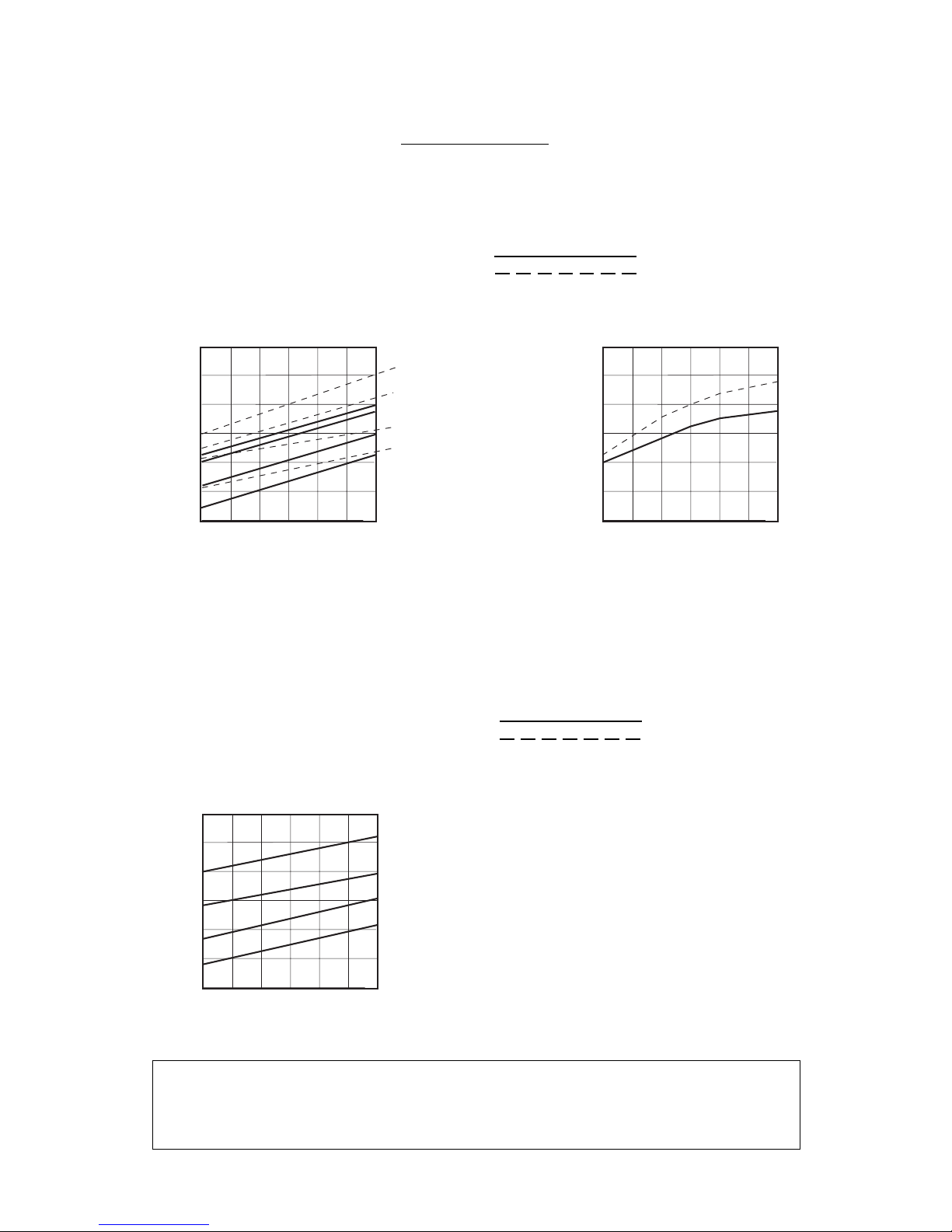
SPECIFICATIONS
NOTE. Daily ice capacity is directly related to condenser air water inlet temperature, water
temperature to make ice - and age of machine.
To keep your SCOTSMAN MAR performing at is maximum capacity, it is necessary to perform
periodic maintenance as outlined on page 29 of this manual.
MAR 56
AIR & WATER COOLED MODELS
THICK SCALE ICE
THIN SCALE ICE
ice making capacity
500
450
400
350
300
250
200
Kg./24 h
38
°C
32 27
21
15
°C
10
21
32
38
o
AIR COOLED MODELS
WA TER TEMPERATURE
AMBIENT TEMPERATURE
ICE PRODUCED PER 24 HRS.
32
38
WATER COOLED MODELS
10 5
10
21
500
450
400
350
300
250
200
Kg./24 h
38
°C
32 27
21
15
°C
DE 10 A' 38
o
WA TER TEMPERATURE
AMBIENT TEMPERATURE
ICE PRODUCED PER 24 HRS.
10 5
MAR 76
AIR & WATER COOLED MODELS
ice making capacity
THICK SCALE ICE
THIN SCALE ICE
AIR COOLED MODELS
540
500
460
420
380
340
300
Kg./24 h
38
°C
32 27
21
15
°C
o
WA TER TEMPERATURE
AMBIENT TEMPERATURE
ICE PRODUCED PER 24 HRS.
10 5
10
21
32
38
Page 5
Page 5
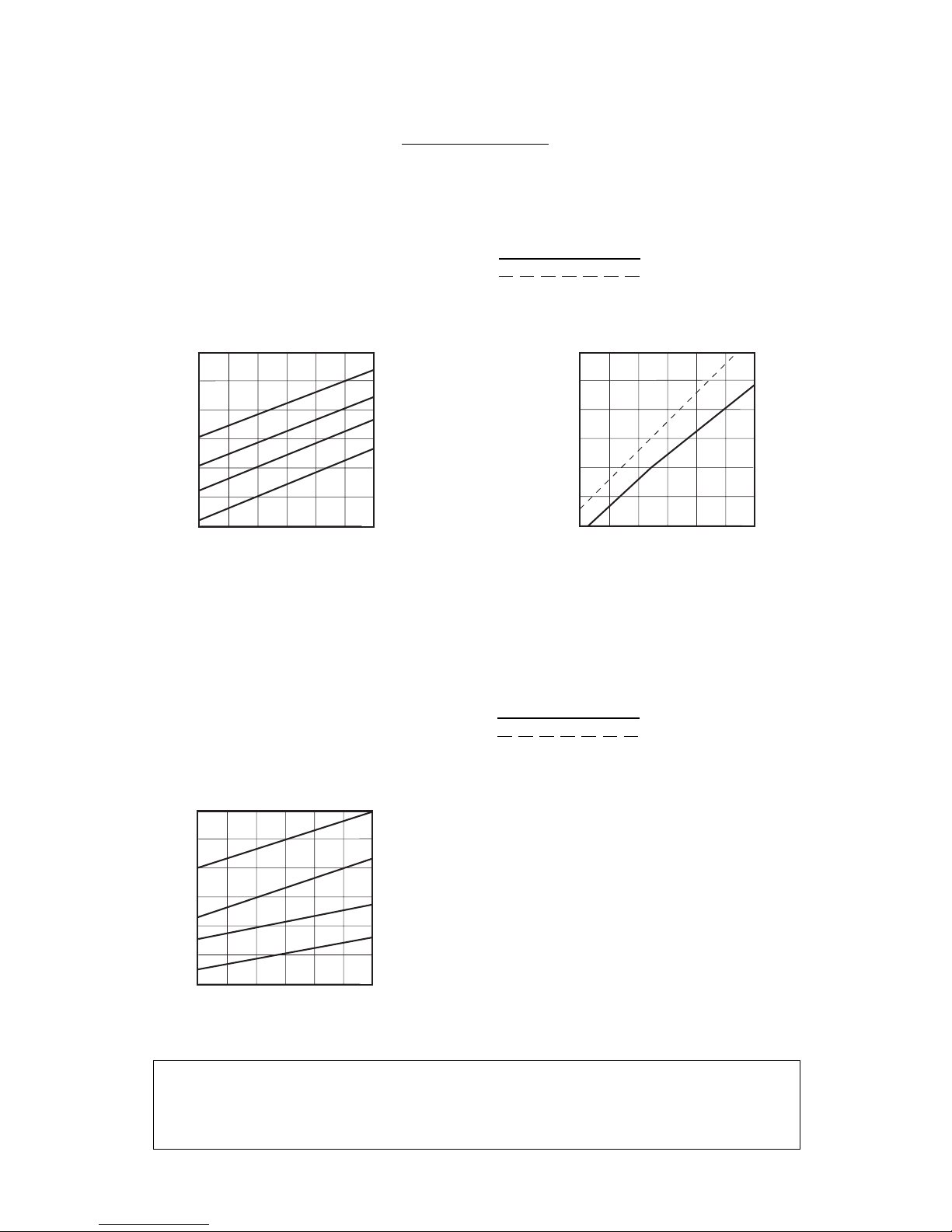
SPECIFICATIONS
NOTE. Daily ice capacity is directly related to condenser air water inlet temperature, water
temperature to make ice - and age of machine.
To keep your SCOTSMAN MAR performing at is maximum capacity, it is necessary to perform
periodic maintenance as outlined on page 29 of this manual.
MAR 106
AIR & WATER COOLED MODELS
THICK SCALE ICE
THIN SCALE ICE
ice making capacity
MAR 126
AIR & WATER COOLED MODELS
ice making capacity
THICK SCALE ICE
THIN SCALE ICE
AIR COOLED MODELS
750
700
650
600
550
500
450
Kg./24 h
38
°C
32 27
21
15
°C
o
WA TER TEMPERATURE
AMBIENT TEMPERATURE
ICE PRODUCED PER 24 HRS.
10 5
10
21
32
38
WATER COOLED MODELS
800
750
700
650
600
550
500
Kg./24 h
38
°C
32 27
21
15
°C
DE 10 A' 38
o
WA TER TEMPERATURE
AMBIENT TEMPERATURE
ICE PRODUCED PER 24 HRS.
10 5
AIR COOLED MODELS
1000
950
900
850
750
650
600
Kg./24 h
38
°C
32 27
21
°C
o
WA TER TEMPERATURE
AMBIENT TEMPERATURE
ICE PRODUCED PER 24 HRS.
10
21
32
38
Page 6
Page 6
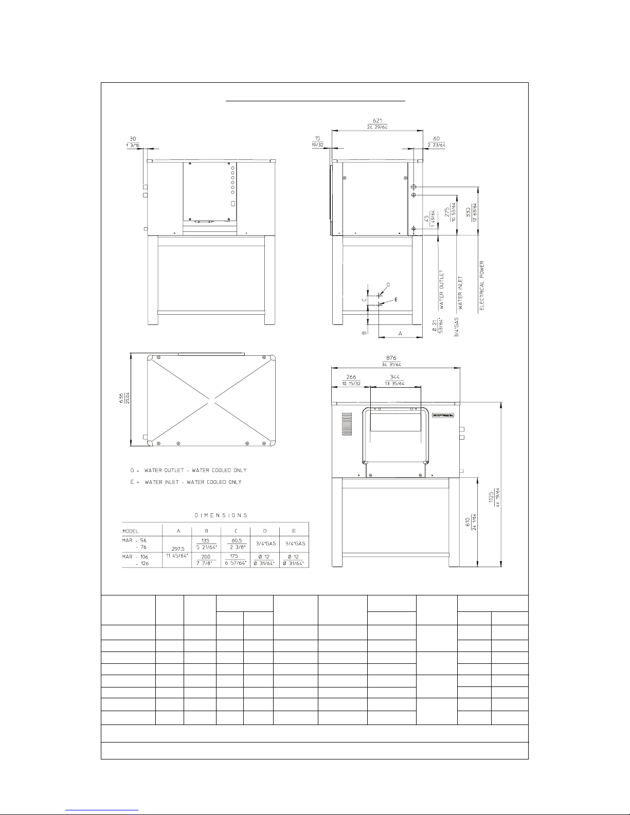
MAR 56-76-106-126 - SPECIFICATIONS
BASIC ELECTRICALS: 400/50/3N
* at 21 °C amb. / 15 °C water temp.
Water req. (l/h) Total Amps.
MODELS Finish
* Cond. Prod. 400 V kg. lbs.
MAR 56 AS Air 2 16 2.2 5 x 1.5 2.7 Stainless 194 427
MAR 56 WS Water 2 225 16 2.2 5 x 1.5 2.7 Steel 174 383
MAR 76 AS Air 2.5 21 2.5 5 x 1.5 2.7 Stainless 204 450
MAR 76 WS Water 2.5 300 21 2.5 5 x 1.5 2.7 Steel 201 442
MAR 106 AS Air 4 30 3.5 5 x 1.5 5 Stainless 221 487
MAR 106 WS Water 4 480 30 3.5 5 x 1.5 5 Steel 217 417
MAR 126 AS Air 4.5 41 4.5 5 x 1.5 6.5 Stainless 226 497
MAR 126 WS Water 4.5 41 4.5 5 x 1.5 6.5 Steel 222 488
Cond. Compr. Power Minimum
Unit (HP) (KW) wire size (mm)
Shipping weight
Page 7
Page 7
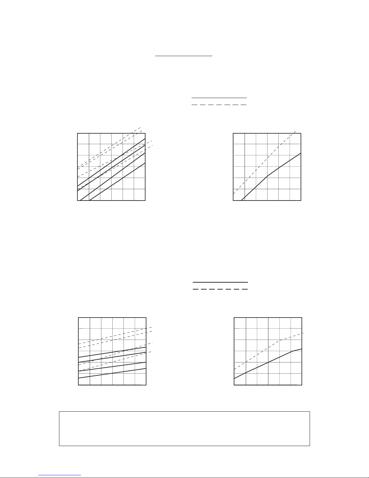
SPECIFICATIONS
NOTE. Daily ice capacity is directly related to condenser air water inlet temperature, water
temperature to make ice - and age of machine.
To keep your SCOTSMAN MAR performing at is maximum capacity, it is necessary to perform
periodic maintenance as outlined on page 29 of this manual.
MAR 206
AIR & WATER COOLED MODELS
ice making capacity
THICK SCALE ICE
THIN SCALE ICE
1700
1600
1500
1400
1300
1200
1100
Kg./24 h
38
°C
32 27
21
15
°C
32
38
AIR COOLED MACHINES
WA TER TEMPERATURE
AMBIENT TEMPERATURE
ICE PRODUCED PER 24 HRS.
32
38
WATER COOLED MACHINES
10 5
10
21
1900
1800
1700
1600
1500
1400
1300
Kg./24 h
38
°C
32 27
21
15
°C
DE 10 A' 38
o
WA TER TEMPERATURE
AMBIENT TEMPERATURE
ICE PRODUCED PER 24 HRS.
10 5
10
21
MAR 306
AIR & WATER COOLED MODELS
ice making capacity
2600
2400
2200
2000
1800
1600
1400
Kg./24 h
38
°C
32 27
21
15
°C
32
38
AIR COOLED MACHINES
WA TER TEMPERATURE
AMBIENT TEMPERATURE
ICE PRODUCED PER 24 HRS.
32
38
WATER COOLED MACHINES
10 5
10
21
2800
2600
2400
2200
2000
1800
1600
Kg./24 h
38
°C
32 27
21
15
°C
DE 10 A' 38
o
WA TER TEMPERATURE
AMBIENT TEMPERATURE
ICE PRODUCED PER 24 HRS.
10 5
10
21
THICK SCALE ICE
THIN SCALE ICE
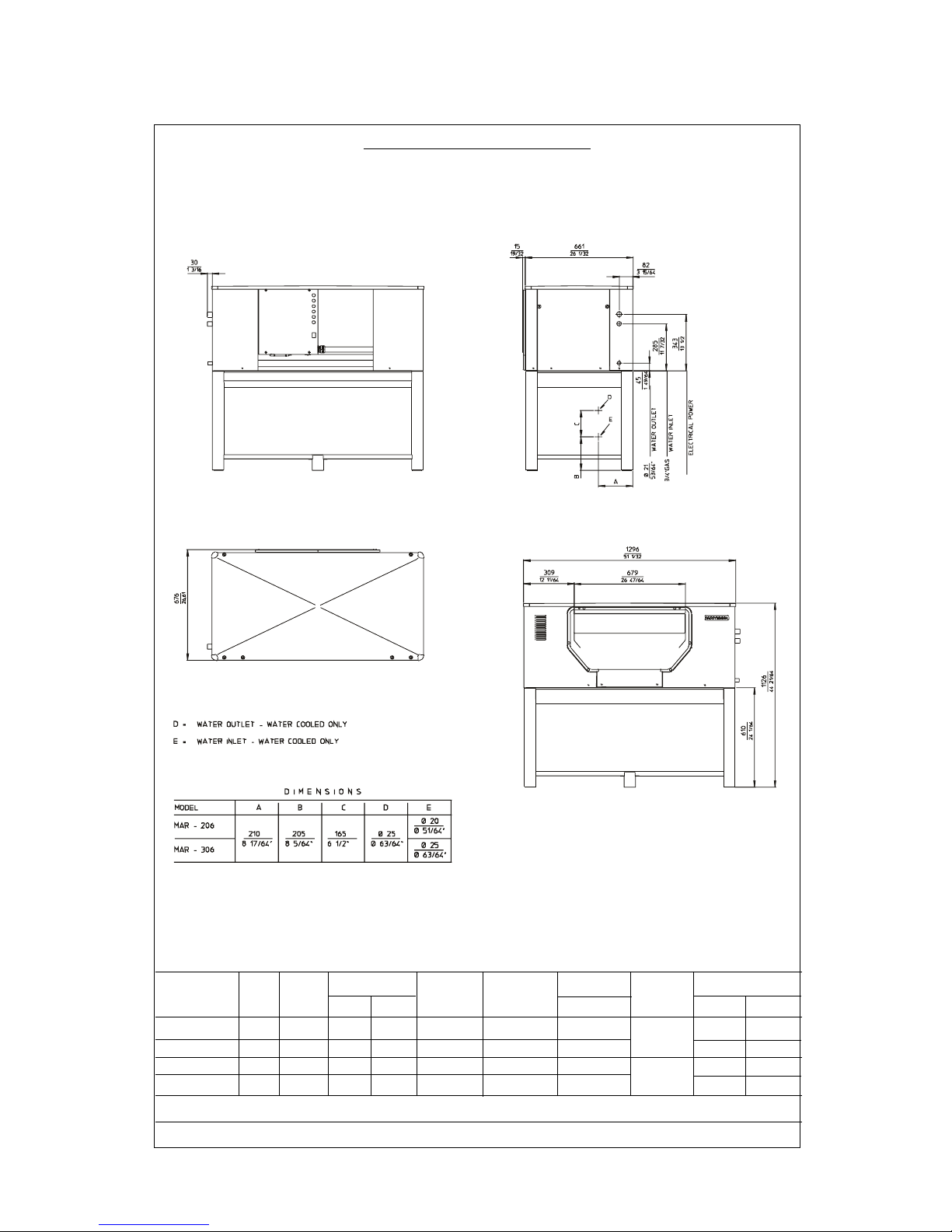
MAR 206-306 - SPECIFICATIONS
BASIC ELECTRICALS: 400/50/3N
* at 21 °C amb. / 15 °C water temp.
Water req. (l/h) Total Amps.
MODELS Finish
* Cond. Prod. 400 V kg. lbs.
MAR 206 AS Air 5 69 7 5 x 2.5 17 Stainless 374 824
MAR 206 WS Water 5 1200 72 7 5 x 2.5 10 Steel 369 813
MAR 306 AS Air 10 88 10 5 x 4 20 Stainless 383 844
MAR 306 WS Water 10 1600 94 10 5 x 4 20 Steel 413 910
Cond. Compr. Power Minimum
Unit (HP) (KW) wire size (mm)
Shipping weight
Page 8
Page 9
Page 9
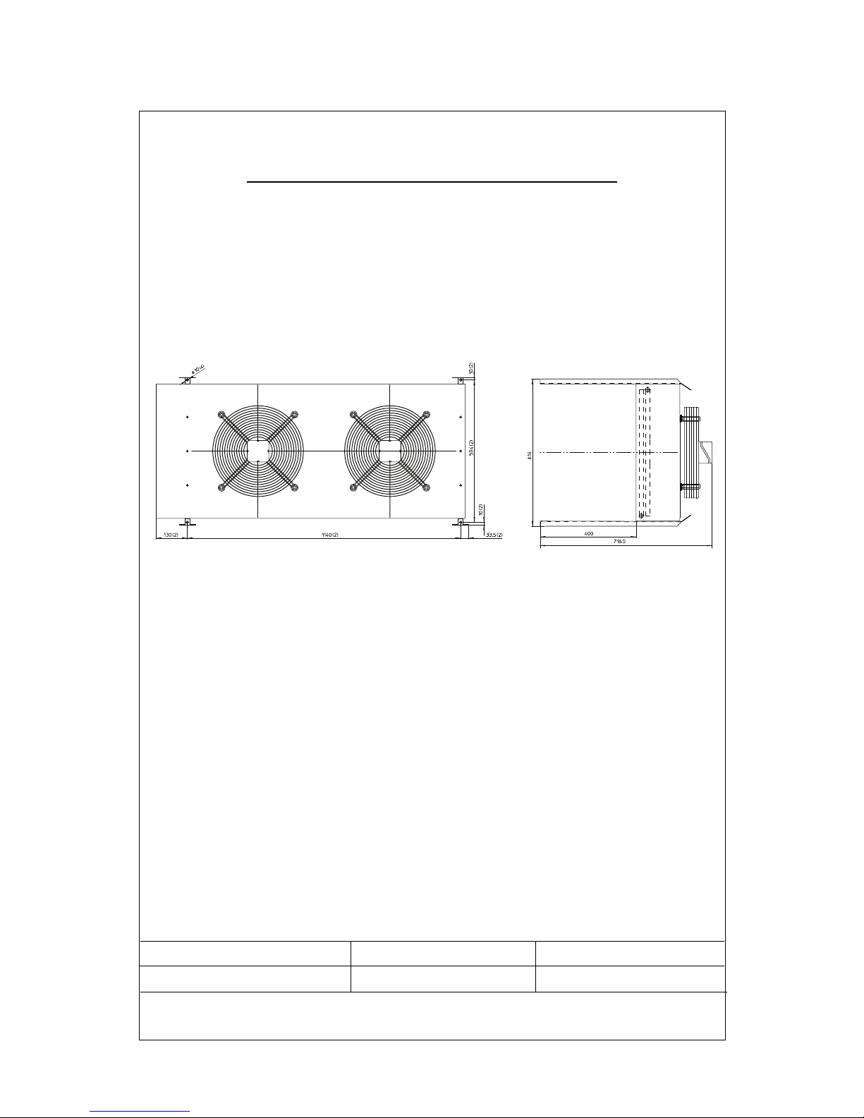
CONDENSER CAPACITY FAN MOTOR AIR FLOW
20 KW - 17200 Kcal/h 230/50/1 V - 0,8 A 4320 m3/h
MAR 306 REMOTE CONDENSER
TECHNICAL SPECIFICATIONS

Page 10
Page 10
SECTION I
GENERAL INFORMATION & INSTALLATION
1. DESCRIPTION
An attractive compact cabinet of stainless steel
with control panel lights on the front. All panels
are removable to allow easy access to electrical
and mechanical components for cleaning and
maintenance.
Sealed Refrigeration System
To provide quite efficient operation of the ice
maker, the compressor is mounted on rubber
cushions. The water cooled models have a tube
within tube condenser with water regulation valve for correct condensing water flow. The air
cooled models, except the MAR 306 have a built
in condenser in copper and aluminium with the
fan motor controlled by pressure control. The
evaporator drum is powered by a separate drive
motor connected by a V-belt and pulley system to
a double gear box. The refrigerant used is R 404a
controlled by automatic expansion valve.
Storage Bin or Ice Room
Since the MAR Scale is a continuous flow type
ice maker and does not have its own attached
storage bin, it is necessary to use an auxiliary bin
or a pre-fabricated ice room for appropriate ice
storage.
Ice storage situations are of two kinds:
a) Short term storage
b) Extended terms storage
Being, as stated, scale ice made by MAR
machines flat, dry and subcooled, therefore with
the tendency to stick toghether, particular
attention is required for proper ice storage
conditions for better ice handling. An insulated
ice storage bin or rooms is always required, then
according to ice end use application, this can be
refrigerated on non-refrigerated.
Also a weight volume ratio of 2,1 cu. mt. per
ton, must be taken into consideration for correct
ice storage.
a) Non-refrigerated room for short term
storage.
The scale ice is produced continuously for 24
hours per day, whereas the use period is
generally for no longer than 8 hours per day.
Therefore storage facilities should be provided
to accomodate a minimum of 16 hours of
production, this means that every scale ice
machine must be installed with a properly
insulated storage room which should have a
minimum capacity of 2/3 the daily ice
production.
With a well insulated room and duly subcooled
scale ice, the limited losses of heat throught
the walls of a properly designed room with
adequate arrangements, are largely offset,
and excess melting will not occur. In most
situations where whole quantity of ice produced
is being used on a daily basis, it is not necessary
to provide cooling for the ice storage room.
b) Refrigerated room for extended storage
and long distance conveying.
When scale ice is to be transported at a
considerable distance, such as aboard fishing
vessels, or in locations with normal ambient
temperatures conditions, or when used in
industrial plants where demand is intermittent,
its subcooling power must be absolutely
preserved in the storage bin by a proper
cooling system keeping air temperature at a
pre-established and constant value. The ideal
ice storage room is the type with mechanically
refrigerated jacket space surrounding the ice
bin. Good practice calls for an ice storage
capacity of about two times the daily ice
machines production with an inside temperature of -6°C minimum (20°F).
2. UNPACKING AND INSPECTION
1. Call your authorized SCOTSMAN Distributor
od Dealer for proper installation.
2. Visually inspect the exterior of the shipping
container and skid and any severe damage
noted should be reported to the delivering
carrier; and a concealed damage claim filled
subject to internal inspection, with carrier
representative present.
3. Remove the packing and remove the shipping
bolts and the shipping base or skid.
4. When necessary, install the leg levellers in
the cabinet base sockets; then, raise the
cabinet to the upright position.
5. Remove screws and shipping tapes and all
doors and service panels from the cabinet and
inspect for any concealed damage.
Notify carrier of any concealed damage claims
as stated in step 2 above.
6. Remove all internal support packing, tape
and wires in machinery compartment.
7. Check that refrigerant lines do not rub or
touch lines or surfaces and that fan blades, if
any, moves freely.
8. Check that compressor is snug on all mounting
pads.
9. Use clean damp cloth or disposable paper
wiper to wipe clean the exterior surface of the
cabinet.
Page 11
Page 11
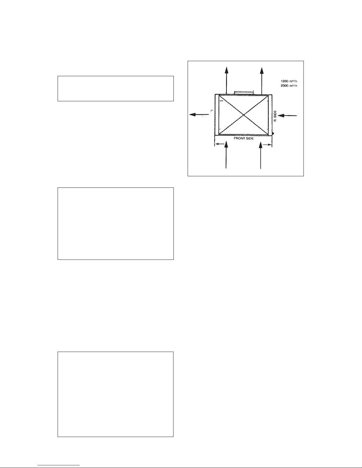
CONDENSING AIR FLOW SCHEMATIC
2. Erection - For elevations in excess of four
feet or in close quarters, chain falls of fork lift
truck should be used. For location under four
feet, the use of skid boards and rollers is practical.
3. Machine Site - When selecting the permanent
location of air cooled machines, consideration
must be given to volume size of the room and to
ventilation facilities for easy heat removal around
the machine.
In doing this it worths to take on account that:
– MAR 56 AS - has a condenser heat rejection
of 3000 Kcal/hr and fan motor draws air for
1200 m3/h.
– MAR 76 AS - has a condenser heat rejection
of 4900 Kcal/hr and fan motor draws air for
1200 m3/h.
– MAR 106 AS - has a condenser heat rejection
of 7500 Kcal/hr and the two fan motors draw
air for 1200 m3/h each.
– MAR 126 AS - has a condenser heat rejection
of 9750 Kcal/hr and the two fan motors draw air
for 1200 m3/h each.
– MAR 206 AS - has a condenser heat rejection
of 11000 Kcal/hr and the two fan motors draw
air for 2000 m3/h each.
– MAR 306 AS - has a condenser heat rejection
of 17200 Kcal/hr and the two fan motor draw air
for 4320 m3/h in total.
4. Position the MAR in the selected permanent
location level the cabinet on both the left-to-right
and front-to-rear directions. The levelling legs
can be adjusted with an opened wrench.
(See unit layout and dimensions at page 6 and 8).
10. See DATAPLATE on the cabinet base and
check that the location source voltage
corresponds with the voltage specified on
the dataplate.
CAUTION - Unproper voltage supplied to
the icemaker will void your parts
replacement program.
11. Remove the Manufacturer's registration Card
from its envelope and fill in all spaces
including: Model Number and serial Number
taken from the aluminium plate located on
the front of the Chassis base, with Front
Panel removed.
Forward the completed, self addressed,
registration card to the Scotsman Europe
Frimont Factory.
3. LOCATION AND LEVELLING
WARNING - The MAR Flakers are NOT
designed for outdoors installation where
air temperature are below 5°C (40°F) or
above 40°C (100°F) and the water temperature is below 5°C (40°F) or above 35°C
(95°F).
Extended periods of operation at
temperatures exceeding these limitations
will constitute misuse, under the terms of
the SCOTSMAN Manufacturer's limited
warranty coverage.
1. Stands - A special stands should be built if
the machine is located beside the bin.
Care should be exercised in making the
stand strong enough to support the weight.
In designing the stand plan for the servicing
of the machine from front, top and sides.
It is also possible to locate the machine on
top of the bin. Care should be used in selecting
a bin that has been specially reinforced.
Standard bins are usually not sufficiently
reinforced for this purpose. An unsteady
platform will cause excessive vibration.
Specially built bins can provide proper support
and allow for a servicing platform.
WARNING - Air Cooled version of MAR 76
,
MAR 106, MAR 126 and MAR 206 have the
condensing air exhaust throughout the
lower rear area (ice spout side) therefore
it is necessary to avoid to position the ice
maker with the rear side against any sort
of wall that will prevent proper warm air
dissipation.They must
have on their rear
side an air gap of 200 mm.
MAR 56 has the
air cooled condenser on the right side
while MAR 306 has a se-parate remote air
cooled condenser. (See instructions for
remote condenser at 6).
MAR 76-106-126
MAR 206
MAR 56
MAR 76-106-126
MAR 206
MAR 56
SIDE
MAR 106 MAR 206 -

Page 12
Page 12
4. ELECTRICAL CONNECTIONS
The machine has been wired ready for electric
connections. See nameplate for current
requirements to determine wire size to be used
for electrical hook-up. The MAR flaker requires a
solid earth ground wire. See wiring diagram.
Be certain the unit is connected to its own electrical
circuit and individually fused.
The maximum allowable voltage variation, should
not exceed ten percent of the nameplate rating,
even under starting conditions.
Low voltages can cause erratic operation and
may be responsible for serious damage to the
overload switch and motor windings.
All external wiring should conform to the National,
State and local electrical permit and services of
a licensed electrician will be required.
WARNING - The compressor is equipped
with a crankcase heater which has to be
energized even when the ice maker is
switched-off. So, make sure to connect
the unit with the compressor crankcase
heater constantly energized. After long
inoperative periods remember to give
current to the heater 4 hours before the
ice-maker start-up.
Fuse protection of the unit should be made as
follows:
MAR 56-76-106-126-206 - 3x16 Amps/400V
MAR 306 WS - 3x24 Amps/400V
MAR 306 ASR - 3x32 Amps/400V
WARNING - Drum drive motor is threephases type. At unit start up, correct wiring
is assured by 3 phases monitoring relay
at power in. In addition proper drum
rotation speed is monitored by a Hall
Effect sensor. In case the drum is not
rotating at all or it rotates too slow (less
then 1/4 turn every 30 seconds) a special
Electronic Control trips the unit OFF so to
avoid that compressor can operate with
the drum OFF (in case of fiber keys
, drive
motor or gear reducer breakage).
In case of any field drive motor replacement,
care must be taken to its wiring, checking the
correct evaporator drum rotation that MUST
be toward ice blade.
In case of wrong evaporator drum rotation,
turn the unit OFF and exchange two phases
connection at drive motor control box.
5.
WATER SUPPLY AND DRAIN CONNECTIONS
Separate water supplies are recommended.
A.Evaporator or ice making supply water should
be run through a hand shut-off valve before
entering unit. Evaporator supply water
connection has a 3/4" male pipe fitting. This
line also has factory installed water strainer
internally mounted. Incoming water goes
through the float reservoir and then to the
drum reservoir. Connect to a good cold water
supply with minimum 1/2 O.D. line. A check
valve on this line will be required in some
cases depending on local plumbing codes.
The recommended minimum water pressure
is 1 bar (14 Psi). Do not operate this unit with
fresh water supply below 1 bar (14 Psi).
Maximum water pressure 5 bar (70 Psi).
B.The condenser water supply line connects to
the following fitting sizes:
MAR 56 - 76
3/4" gas male
MAR 106 - 126 12 mm O.D. fitting
MAR 206 20 mm 0.D. fitting
MAR 306 25 mm
Water supply line size must be adequate to
water flow which, at 15°C temperature water, is:
225 lt/hr for MAR 56
300 lt/hr for MAR 76
480 lt/hr for MAR 106
lt/hr for MAR 126
1200 lt/hr for MAR 206
1600 lt/hr for MAR 306
Incoming water goes throughout the water
regulating valve first and then to the water
cooled condenser. Observe arrow on water
regulating valve. Water supply must be installed
to conform with local code. In some case a
licensed plumber and/or a plumbing permit will
be required.
Water Quality
Water quality is a factor of extreme importance
for good operation of MAR machine. Water
shouldn't be too hard neither too soft.
Hard water will tend to create mineral deposits in
water reservoir, evaporator drum and scraping
blade, rendering rough the chute surface which
prevents ice scales from sliding properly into ice
channel. On the contrary, water too soft, (demineralized) will cause the ice skin to stick
excessively on drum surface rendering difficult
the scraping operation of same.
The ideal water should have a total hardness
of about 15-20 french degrees.
Precaution Against Water Frost
Like for any other ice maker all necessary
measures must be taken when the cold season
is approaching to protect the water supply line
and the MAR water system against winter
freezing. If cooling tower is used several
precautions should be observed, too.
1. Leave water regulating valve in the system.
2. Separate the make-up water for the reservoir
from the tower water.
3. Use 3/4" tower water lines or larger, depending
on the lenght of run. Over 30 feet, use 1" O.D.
lines.
4. NOTICE: a cooling tower can freeze in the
winter time and the MAR flaker will be in
operation 12 months per year. An indoor tower
and pump can be used with outdoors air ducted
in and out if the fan cycles on water temperature to prevent freezing. An indoor sump can
be used. An auxiliary tower and city-water
hook-up will prove satisfactorily in some
climates. Fresh water in the winter and tower
water during the summer. Consult your tower
and pump manufacturers for proper sizing. In
no event should less than a Nominal 3 to 4 tons
tower, or less than 3/4 HP high pressure tower,
or less than 3/4 HP high pressure tower pump
be used.
Page 13
Page 13
C.Drain (When not re-used).
The recommenden tubes for the condenser
waste line are:
- MAR 56-76 - 3/4" GAS female fitting.
- MAR 106-126 - 12 mm I.D.
- MAR 206-306 - 25 mm I.D.
Water drip tray drain line is 21 m/m I.D. Tube
to be connected with clamp to a 21 m/m hose
barbed fitting for all models.
Waste water line must run to an open trapped
vented drain. If drain is a long run, allow a pitch
of 3 cm per meter.
6. REMOTE AIR-COOLED CONDENSER
AND PRECHARGED REFRIGERANT
LINES INSTALLATION (MAR 306 ONLY)
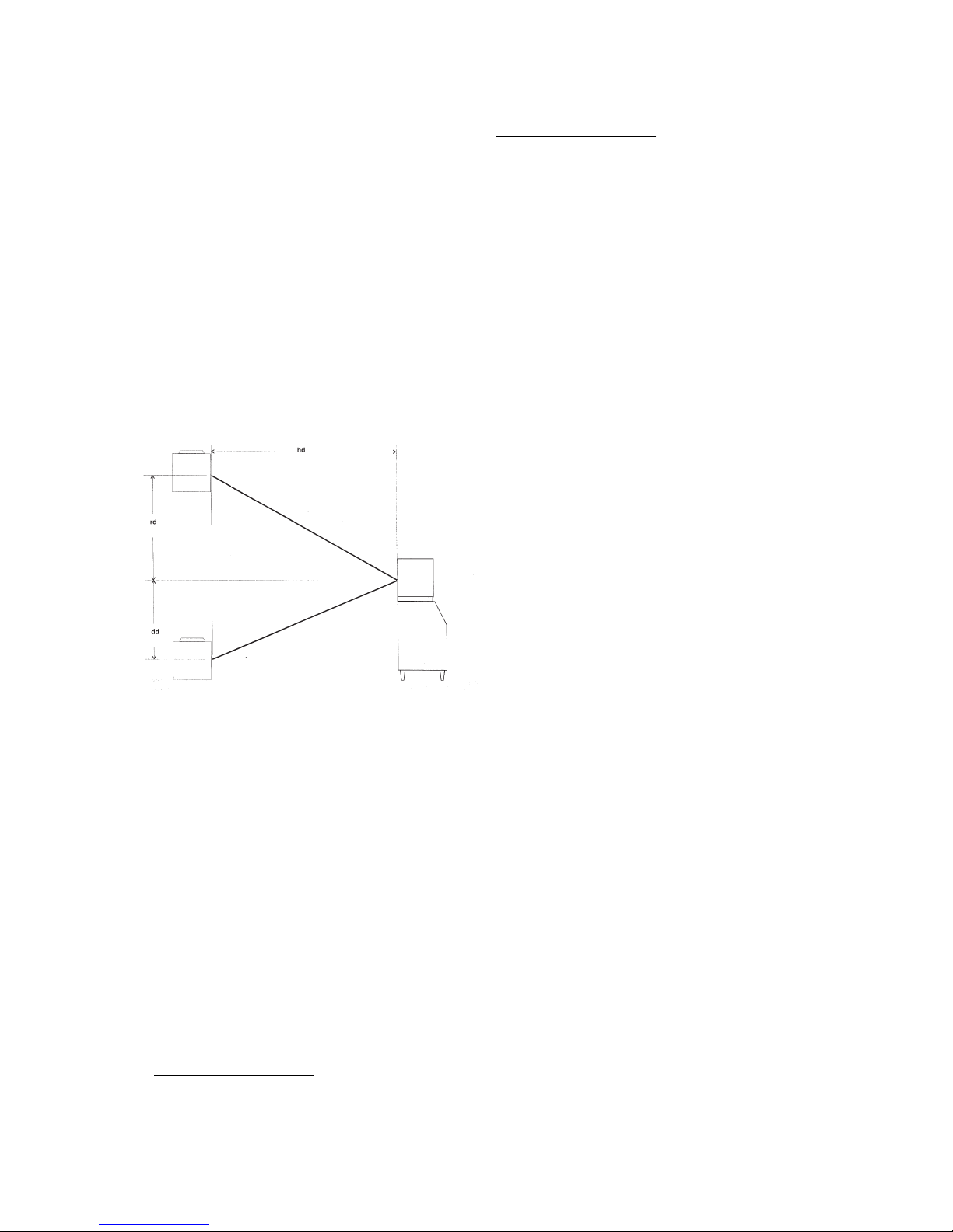
Use the following for planning the placement of
the condenser relative to the ice machine
Location Limits - condenser location must
not exceed ANY of the following limits:
• Maximum rise from the ice machine to the
condenser is 3 physical meters
• Maximum drop from the ice machine to the
condenser is 1 physical meter
• Physical line set maximum length is 6 meters
• Line set length maximum is 9 meters.
Calculation Formula:
• Drop = dd x 6.6 (dd = distance in meters)
• Rise = rd x 1.7 (rd = distance in meters)
•
Horizontal Run = hd x 1 (hd = distance in meters)
• Calculation: Drop(s) + Rise(s) + Horizontal
Run = dd+rd+hd = Calculated Line Length.
Configurations that do NOT meet these
requirements must receive prior written
authorization from Scotsman.
Do NOT:
• Route a line set that rises, then falls, then rises.
• Route a line set that falls, then rises, then falls.
Calculation Example 1:
The condenser is to be located 0.9 meter below
the ice machine and then 3 meters away horizontally.
0.9 mt x 6.6 = 5.94 + 3 = 8.94. This location would
be acceptable.
Calculation Example 2:
The condenser is to be located 4 meters above
and then 3 meters away horizontally.
4 x 1.7 = 6.8 6.8+3 = 9.8.
9.8 is greater than
the 9 maximum and is NOT acceptable.
Operating a machine with an unacceptable
configurationg will void the refrigeration
system warranty.
In a crate, separated by the unit crate are packed:
1. The air-cooled condenser mounted on the
platform base with the electrical junction box,
condenser shround, fan motors, fan protection
grid, fan motor speed, control and the
refrigerant lines connection couplings.
2. One set of pre-charged refrigerant line with
connection couplings on both ends of following
variety. Liquid I.D. 12 m/m - Gas I.D. 16 m/m
- 10 mts length.
The pre-charged refrigerant lines, 6 meters long,
are equipped with self-sealing coupling
connections and can be connected or disconnect
few times without loosing the refrigerant charge.
The electric cord line, approx. 10 meters long,
located on the left side of the unit has to be
connected to the condenser junction box
terminals.
The condenser fan motors are originally wired for
230 V single phase and have the following
specifications:
RPM 1420
WATTS 2x180
AMPS 2x0,80
They operate at 230 V 50 Hz and are controlled
by an Electronic Fan Speed Control set at 16 bar.
A. Location consideration:
1. Limit to 10 meters the lenght of the precharged
refrigerant lines from the ice-maker to the
remote condenser.
2. Maximum vertical rise of 3 meters between
the ice maker and the remote condenser.
3. Best available location, protected from the
extremes of dirt, dust, rain, sun and wind.
B. Unpacking and inspection:
1. Visually inspect the exterior of the shipping
container and any severe damage noted,
should be reported to delivering carrier; and a
concealed damage claim filled subject to
internal inspection with carrier representative
present.
2. Uncrate the remote condenser and precharged refrigerant lines and inspect for any
concealed damage claims, as stated in step 1
above.
3. Check that the pre-charged refrigerant lines
are intact, not kinked, and that there is no
sealed puncture or loss or refrigerant.
Max 3 m
Max 1 m
Condenser
Distance &
Location
Schematic
Remote
Condenser
Located BELOW
Ice Machine
Remote
Condenser
Located ABOVE
Ice Machine
 Loading...