


USER MANUAL MANUALE D’USO
HD22
HD30
17-3121-01 Rev. A

English .....................Page 2
Italiano .....................Pagina 9
1

User Manual for Hotel Dispensers
models
HD22 and HD30
TABLE OF CONTENTS
Warranty ·············································page 2
Installation ············································page 4
Final Check List ·········································page 6
Maintenance ···········································page 7
Failure Analysis ·········································page 7
Cleaning and Mainenance - SERVICE ·····························page 9
WARRANTY:
The warranty conditions are those supplied by the official distributor for your area. In case of parts, only GENUINE
service parts may be used.
Introduction
To the owner or user: This product manual is a source of information about the installation, start up, cleaning and
maintenance of the product.
General Description
The HD22 is a hotel/motel ice dispenser. It is designed to use a Scotsman C0322, C0522or MV 300 cube ice
machine as the source for ice.
The HD30 is a wider version of the HD22 and is designed to use a Scotsman C0330, C530, MV 450 or MV 600
cuber as its source of ice. Additional models may be used, see sales information for details. Ice from the cuber falls
into the insulated hopper, where it is stored until needed. When a user pushes the dispense chute a rotating wheel
scoops the ice up to the top front of the hopper where there is an outlet to the ice chute.
Higher capacity cubers C0830, MV 800 or MV 1000, may also be used, but they require 400 volt 3 Phase power.
2
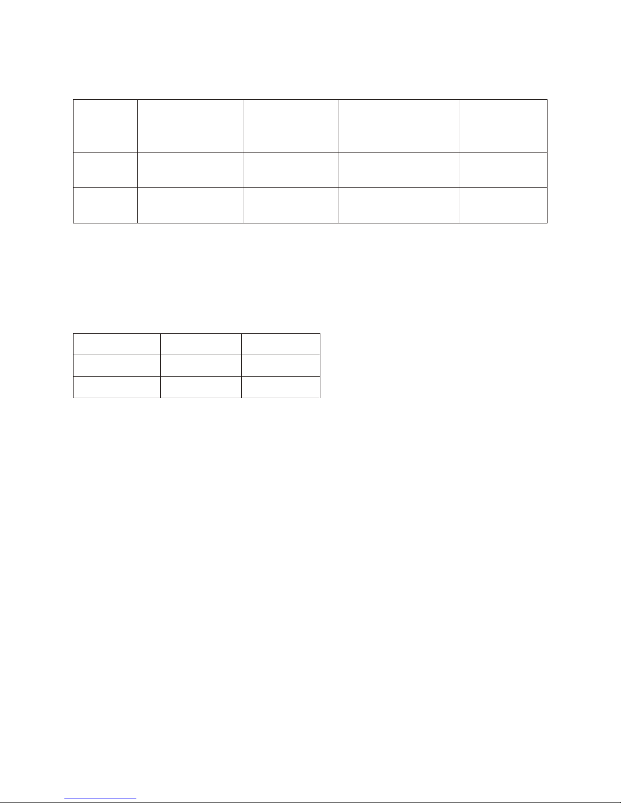
Basic Specifications
Dimensions(mm)
Model
HD22B-6H
HD30B-6H
Basic models dispense ice when their chute is pushed.
w x h x d with
125.4 mm leg
558.8 x 1346 x 851 230/50/1
762 x 1346 x 851 230/50/1
Basic Electrical
volts/hertz/phase
Model Description
Basic 22” model, 50 Hz
Basic 30” model, 50 Hz
Bin Storage
Capacity, ARI
rated
54 kg
81 kg
Specifications & Limitations
This dispenser is designed to be installed and operated indoors, in a controlled environment. Its minimum and
maximum operating temperature limits are the same as those for the ice machine.
Minimum Maximum
Air Temp 10 degrees C 40 degrees C
Voltage 50 Hz 207 253
Check the nameplate, located on the back of the cabinet for specific information.
This appliance can be used by children aged from 8 years and above and persons with reduced physical, sensory or
mental capabilities or lack of experience and knowledge if they have been given supervision or instruction
concerning use of the appliance in a safe way and understand the hazards involved.
Warnings
In case the power cable is damaged, replace it ONLY by QUALIFIED TECHNICIANS so to prevent any possible
risks.
Disconnect the electrical power before beginning any maintenance or cleaning operation.
MAKE SURE YOUR HANDS ARE PROPERLY WIPED DRY.
The electrical disconnect switch and/or the electrical socket must be within hand reach of the installed machine.
IMPORTANT. Do not remove any service panel secured with screws.
The sound level of the unit in operation should be lower than 70 db (A).
Scotsman reserves the right to make design changes and/or improvements at any time. Specifications and designs
are subject to change without notice.
Scotsman assumes no liability or responsibility of any kind for products manufactured by Scotsman that have been
altered in any way, including the use of any parts and/or other components not specifically approved by Scotsman.
3
Models
The Basic version is constructed to deliver ice when the ice chute is pushed in, and it continues to vend ice as long
as the ice chute is held in.
Product Description
All models consist of a plastic lined, insulated hopper mounted to a metal base. The hopper contains a 15 blade
plastic dispense wheel and a stainless steel sweep arm. The top front of the hopper has a removable door to facilitate
maintenance and cleaning by the technician only of the hopper without removal of the ice machine.
The dispense wheel and sweep arm rotate when the dispense drive motor is actuated. The drive motors actuation is
controlled by the agitation timer or the vend switch. When the ice dispense chute is pushed back it moves the
actuation lever up. The actuation lever releases the chute door and pushes the vend switch arm up. When the vend
switch arm has moved a preset distance the vend switch contacts close, providing power to the dispense drive motor.
Ice is delivered to the top end of the ice chute by the dispense wheel and it slides down the chute to the container
below. The container rests on a grill, the grills openings are over the ice catch pan, and any spilled ice goes there.
The grill has a flange at the front to help contain the ice if it spills during vending. After the ice dispense chute is
released, the ice chute door closes to stop ice flow. Ice in the chute will eventually melt. Melted ice water is routed
to the drain through a hose attached to the bottom of the chute. Spilled ice is contained in an insulated ice catch pan.
Melted ice water from the ice catch pan is routed to the drain. User debris is kept away from the drain in the catch
pan by a slotted shield.
The side and front exterior panels are stainless
steel. The vending area and top panel are made
of plastic.
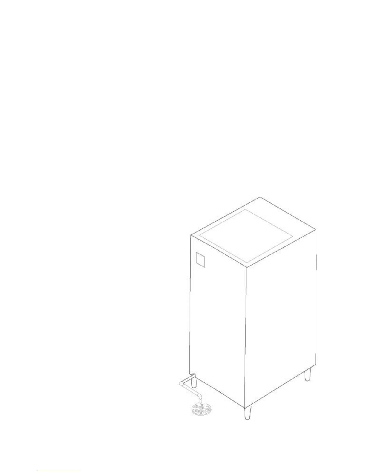
Unpacking
After removing the carton, check for the
loose-shipped parts packed in the storage bin.
The parts will include a carton with four legs.
Remove the leg carton and any other
loose-shipped items.
To remove the skid, place part of the carton
behind the unit and tip the unit on its back.
Remove the bolts holding the skid to the base
of the HD dispenser and separate the skid from
the unit.
Install the legs into the base of the unit, using
the holes where the skid bolts were. Turn the
leg leveler part of the legs in all the way,
adjust them later after the unit is in its final
installed position.
Move the dispenser to an upright position and
set it in the location where it will be installed.
Note where drain lines and electrical
connections will be made.
Installation - Plumbing
Drain:
4
All models of the dispenser have a 3/4" FPT drain fitting at the bottom of the back panel. Connect 19 mm rigid
tubing to this connection, a vent is recommended for most installations. Route the drain tubing to the building drain.
Note: Drain fitting material is plastic. If using copper, sweat the copper tube to copper fitting together before
installing on the dispenser.
Note: Keep PVC solvent away from all plastic parts of the dispenser.
Follow all applicable plumbing codes.
Because the drain tubing will be very cold, insulation is recommenced for the tubing.
5

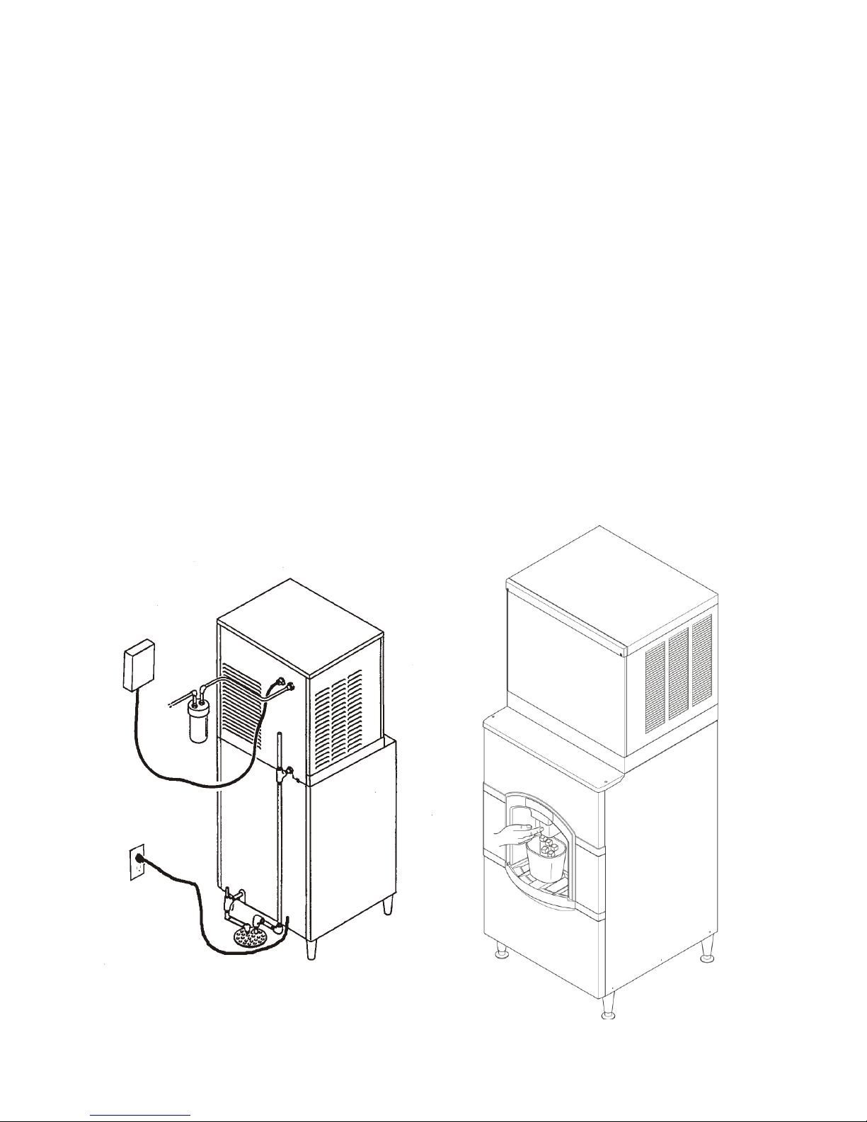
Installation - Electrical and Ice Machine Assembly
The dispenser is supplied with a power cord. Do not use with an extension cord. The unit must be plugged into a
properly grounded outlet.
The distance of the contact opening allows complete disconnection in terms of overvoltage category III.
The devices for disconnection must be incorporated in the power supply line in accordance with the wiring
rules.
The dispenser must be installed so that it is a separate piece of equipment from the ice machine. The drains and
electrical supply must be separate.
Leave a minimum space of 150 mm from walls to allow enough air circulation
The maximum and minimum ambient temperatures for correct operation are a minimum of 10 degrees C and a
maximum of 40 degrees C.
The appliance is not suitable for installation in an area where a water jet could be used.
Follow All Local State and National Codes
Ice Machine
All models: Place the dispenser in the location where it will be used. Level the top edge of the dispenser front to
back and left to right.
Sanitize the dispenser bin with a locally approved sanitizer.
Place the ice machine on the dispenser and secure it to the dispenser with the hardware and straps from the ice
machine. Install it according to the instructions in the manual included with the ice machine.
6
 Loading...