

Page 1

INTRODUCTION
NME650 & FME800
To the own er or user: The ser vice manua l you are
reading is intended to provide you, and the
maintenance or service technician, with the
information needed to install, start up, clean,
maintain, and service this ice system.
This is a modular ice system that fits a variety of
Scotsman ice storage bins.
It feat ur es: fron t servic e for the freezer, gearmotor,
control box, water reservoir, and bin control; an
elect r on i c c ir c ui t for m on i to r i ng ic e an d w ater level;
a thermostatic expansion valve; and HP62 as the
refrigerant.
Table of Contents
FOR THE INSTALLER . . . . . . . . . . . . . . . . . . . . . . . . . . . . . . . . . . . . . . . . . . . 2
SAMPLE BIN AND MACHINE COMBINATIONS . . . . . . . . . . . . . . . . . . . . . . . . . . . . . . 3
FOR THE INSTALLER . . . . . . . . . . . . . . . . . . . . . . . . . . . . . . . . . . . . . . . . . . . 4
FOR THE PLU MBE R . . . . . . . . . . . . . . . . . . . . . . . . . . . . . . . . . . . . . . . . . . . . 6
FOR THE ELEC TR I CIAN . . . . . . . . . . . . . . . . . . . . . . . . . . . . . . . . . . . . . . . . . . 7
START UP . . . . . . . . . . . . . . . . . . . . . . . . . . . . . . . . . . . . . . . . . . . . . . . . . 9
COMPONENT DESCRIPTION . . . . . . . . . . . . . . . . . . . . . . . . . . . . . . . . . . . . . . . 10
ELECTRICAL SEQUENCE . . . . . . . . . . . . . . . . . . . . . . . . . . . . . . . . . . . . . . . . . 13
OPERATION: . . . . . . . . . . . . . . . . . . . . . . . . . . . . . . . . . . . . . . . . . . . . . . . . 14
MAINTENANCE AND CLEANING . . . . . . . . . . . . . . . . . . . . . . . . . . . . . . . . . . . . . 16
SERVICE DIAGNOSIS: . . . . . . . . . . . . . . . . . . . . . . . . . . . . . . . . . . . . . . . . . . 20
REMOVAL AND REPLACEMENT: Bin Controls . . . . . . . . . . . . . . . . . . . . . . . . . . . . . . 24
REMOVAL AND REPLACEMENT: Bearing And Breaker . . . . . . . . . . . . . . . . . . . . . . . . . 25
REMOVAL AND REPLACEMENT: Auger . . . . . . . . . . . . . . . . . . . . . . . . . . . . . . . . . 26
REMOVAL AND REPLACEMENT: Water Seal . . . . . . . . . . . . . . . . . . . . . . . . . . . . . . 27
REMOVAL AND REPLACEMENT: Evaporator . . . . . . . . . . . . . . . . . . . . . . . . . . . . . . 28
REMOVA L AND REP LA C EM E NT : Ge ar mo to r . . . . . . . . . . . . . . . . . . . . . . . . . . . . . . . 29
REFRIGERATION SERVICE: HP62 . . . . . . . . . . . . . . . . . . . . . . . . . . . . . . . . . . . . 30
CIRCUIT BOARD TESTING . . . . . . . . . . . . . . . . . . . . . . . . . . . . . . . . . . . . . . . . 32
Parts lists and wiring diagrams are in the center of this manual, printed on yellow paper.
This manual was printed on recycled paper.
Keep this manual for future reference.
Note this symbol when it appears.
February 1997
Page 1
It is an alert for important safety
information on a potential hazard.
Page 2
NME650 & FME800
FOR THE INSTALLER
These machines fit the following Scotsman
products, check sales literature for other possible
combinations:
B90 and ext ensions (w i th bi n to p KB T 18 )
HTB555 or BH550 using bin top KBT 1 4 or KB T 20
BH800 us ing bin top KBT15 (one unit).
BH800 (two units, no bin top required).
BH900 us ing bin top KBT24.
When installing a new system, check to be sure
that you have everything you need before
beginning:
Correct Bin
Correct Ice Machine
Correct Bin Top (if required)
All kits, l eg s, an d i nf orm a ti o n req uir e d fo r
the specific job.
Installation Limitations:
This ice system is designed to be installed indoors,
in a cont r oll e d environm en t:
Min. Max.
Air Temperature 50
Water Temperature 40
Water Pressu r e 20 PSI 80 PSI
Volta ge (f or 11 5v m od el ) 104 126
(Compared to the nameplate)
Operating the machine outside of the limitations is
misuse and can void the warranty.
0
F1000F
0
F1000F
The nor mal finish for the ice machine i s enamel.
A stain l ess steel panel k it, SPKFM2 1 m ay be f iel d
install ed to convert the uni t to a stainless steel
finish.
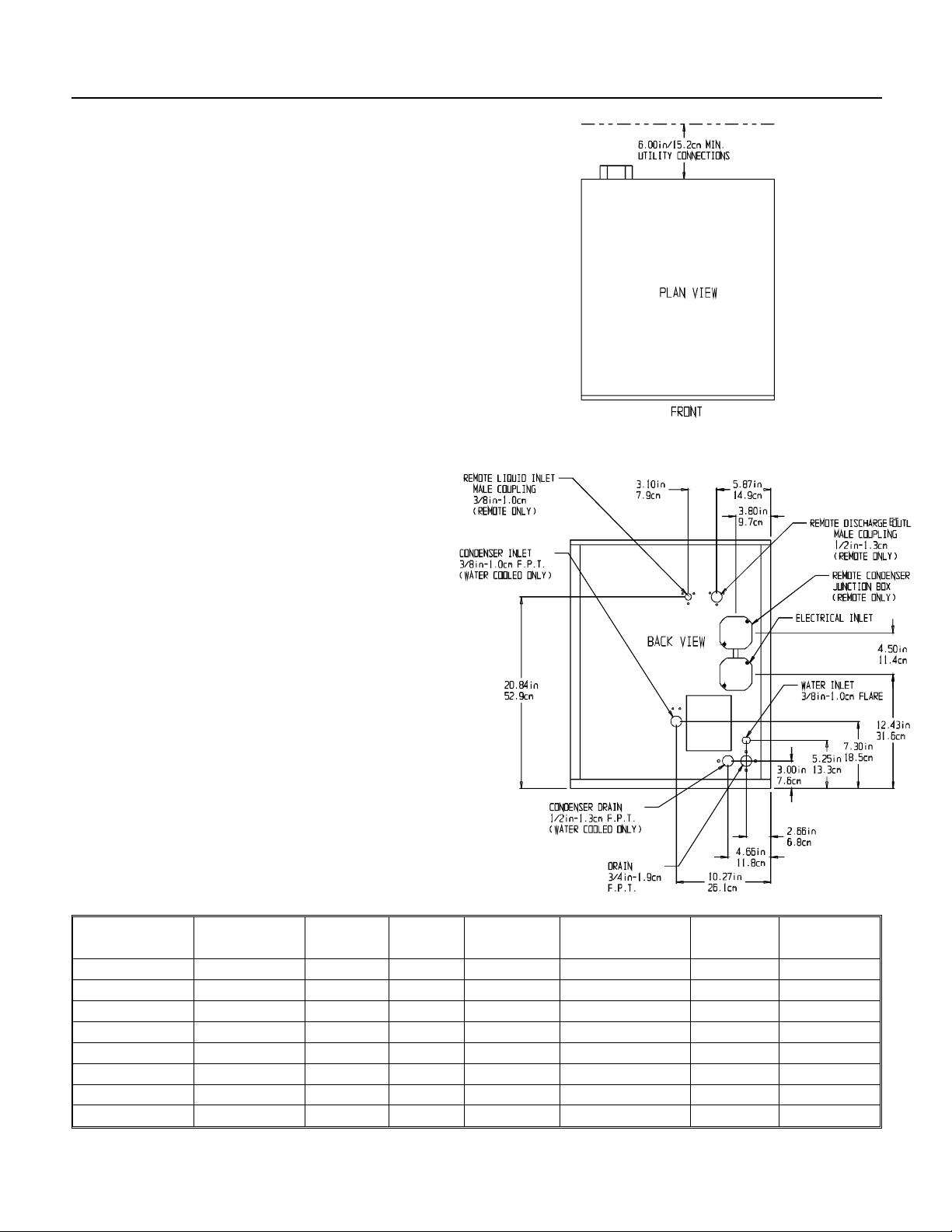
SPECIFICATIONS: ICE MAKER
Model Number Dimensions Basic
Electrical
FME800AE-1A 27" x 21" x 24" 115/60/1 Flake Air 19.5 30 24 ounces
FME800WE-1A same same same Water 18.3 30 20 ounces
FME800AE-6B same 230/50/1 same Air 24 ounces
FME800WE-6B same same same Water 20 ounces
NME650AE-1A same 115/60/1 Nugget Air 19.5 30 24 ounces
NME650WE-1A same same same Water 18.3 30 20 ounces
NME650AE-6B same 230/50/1 same Air 24 ounces
NME650WE-6B same same same Water 20 ounces
Note: Minimum Circuit Ampacity is used to determine wire size and type per national electric code.
Ice Type Condenser
Type
February 1997
Page 2
Minimum
Circuit Ampacity
Max.
Fuse Size
Refrigerant
Charge:
Page 3
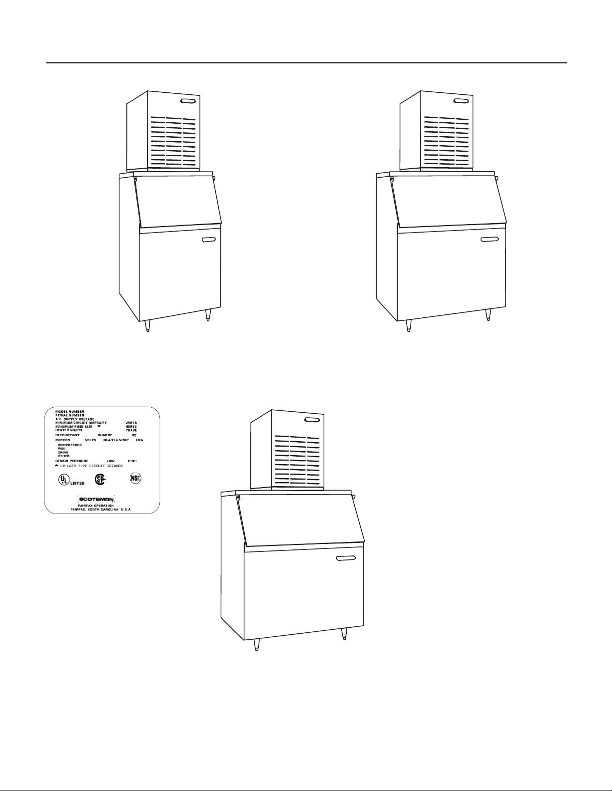
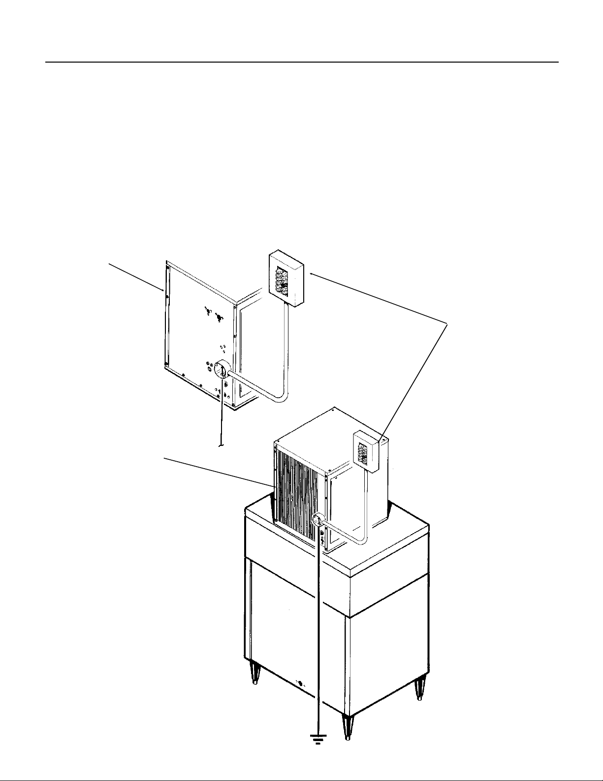
NME650 & FME800
SAMPLE BIN AND MACHINE COMBINATIONS
The Nameplate is
located on the back
of the machine.
FME800 ON BH550*
NME650 ON BH800*
FME800 ON BH900*
*Bin Top Kit Required
February 1997
Page 3
Page 4

NME650 & FME800
FOR THE INSTALLER
Location:
After uncrating and insp ection, the unit is ready for
installation. It is important that the machine be
install ed in a location where it has enough space
around it to be accessible for service, and a
minimum of 6" be allowed at the back for air
circulation on air cooled models. Try to avoid hot,
dirty and crowded locations. Be sure that the
location for the machine is within the
environmental limitations.
Storage Bin:
Tip the storage bin on its back, using parts of the
carton to protect the exterior finish. Install the legs
into the threaded holes in the bottom of the bin.
Turn the leg levelers all the way in preparation for
leveling later. Return the bin to the upright
position, remove paper covering the bin gasket.
Note: Do not push bin into position, but lift it there.
Pushin g a bin, especially one with ice in it, can
cause damage to the legs and the leg mounts.
Install the appropriate bin top on the bin, according
to the instructi ons for the bin top .
Ice Maker:
The machine is heavy, so the use of a mechanical
lift is recommended for lifting the machine high
enough to i ns tall on top of the bi n. After the uni t i s
placed on the bin, line it up so it is even with the
back sid e. Secure the machine to the bi n wi th the
hardware provided with the machine.
Remove the front panel an d r emove any shipping
blocks.
Note: When placing 2 of the s e ma chi n es on a
BH800 without the bin top, removal of the 2
service panels facing each other will make future
service easier:
1. Remove the 2 top panel screws that will face
each other.
2. Remove the 2 service panels that will face each
other .
3. Add a str i p of gasket, such as Scotsman par t
number 19-0503-04, to the 2 base edges that will
face each other and around service panel space
on the 2 panels that will face each other.
When the 2 machines are placed on the bin, the
gaskets will seal the bin top area and the space
between the machines.
Water Limitations:
An ice machine is a food manufacturing plant: it
takes a raw material, water, and transforms it into
a food product, ice. The purity of the water is very
important in obtaining pure ice and in maximizing
product life. This section is not intended as a
complete resource for water related questions, but
it does of fer thes e general r e commendations:
1. Chec k wi t h a w at er tr e atment spec ialist for a
water test, and recommendations regarding filters
and treat m en t.
2. In most cases, the water us ed to make ice
should be filtered or treated, depending upon the
water.
effective in all situations.
is important.
Note:
Scotsman Ice Systems are designed and
manufactured w ith the highest regard for safety
and performance . Th ey m ee t or exceed the
standards of UL, NSF, and CUL.
Scotsman assumes no liability or responsibility of
any kind for pr o du c t s ma nu fa c t ur e d by Sc otsman
that ha ve been alt e r ed in any way, including the
use of any pa r t and/or other compon ents not
specifically ap pr oved by Scotsman.
Scotsman reserves the right to make design
chang es and/or improvem ents at any time.
Specifications and design are subject to change
without notice.
There is no one type of water filter that is
That is why a water test
February 1997
Page 4
Page 5
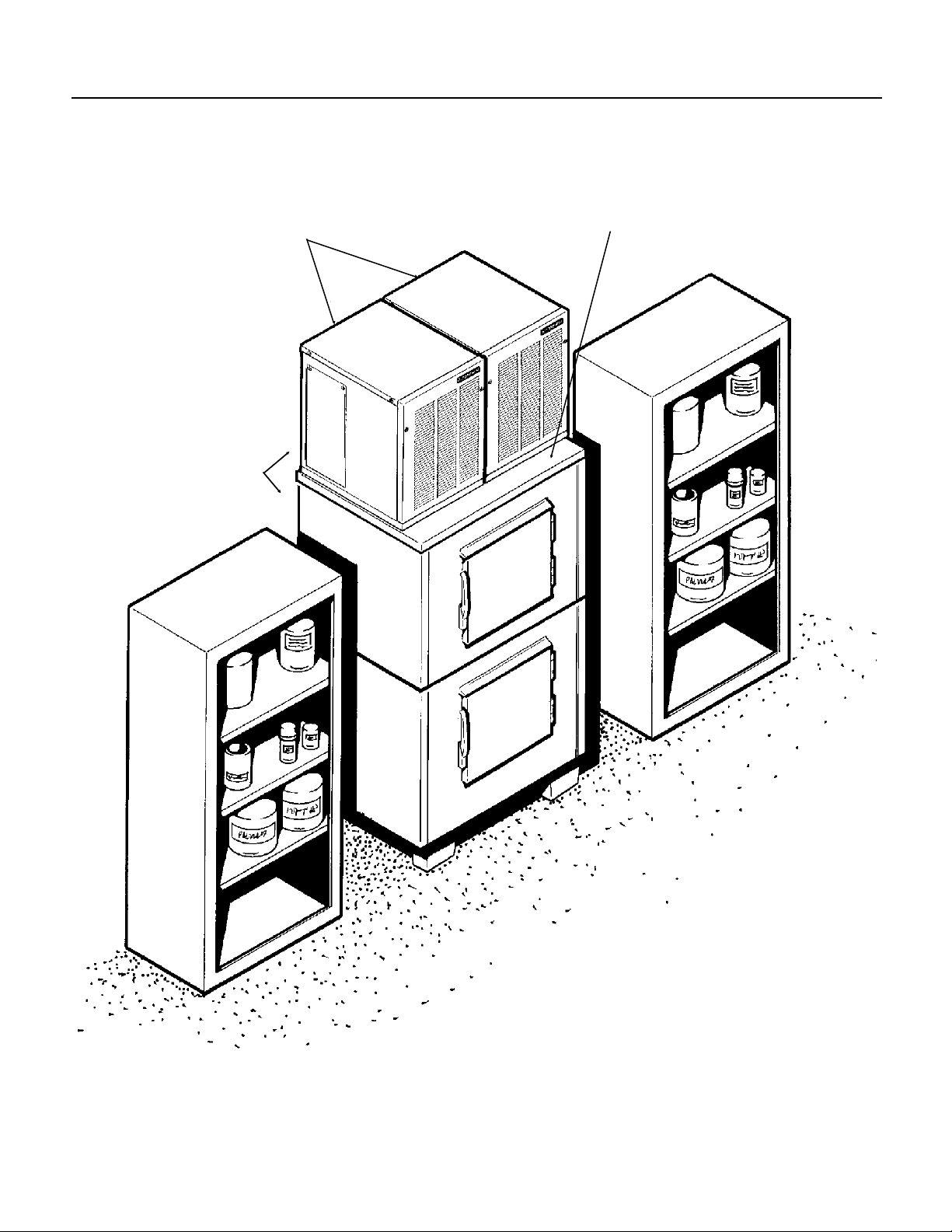
FOR THE INSTALLER: Loc ation
TWO UNITS ON ONE BIN
ALLOW ROOM
FOR AIR
CIRCULATION
AND SERVICE
ACCESS
NME650 & FME800
DO NOT STACK ANYTHING IN
FRONT OF THE MACHINE(S)
February 1997
Page 5
Page 6
NME650 & FME800
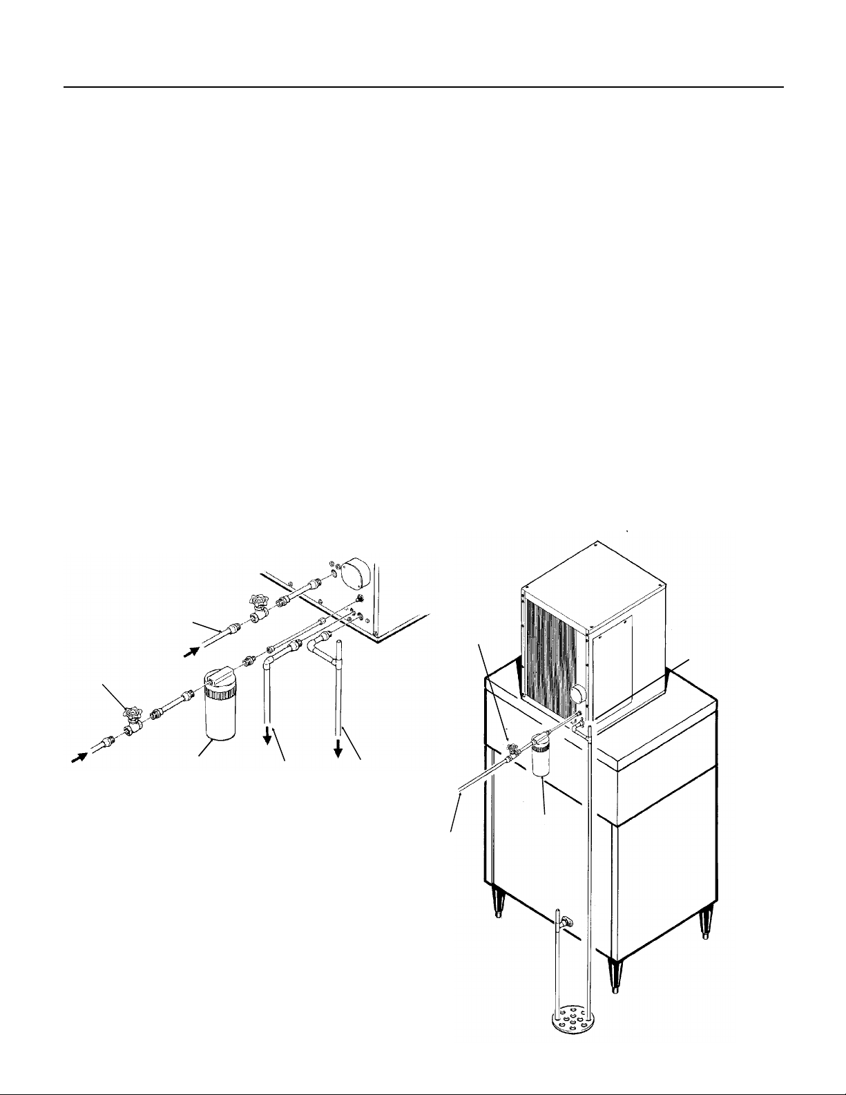
FOR THE PLUMBER
CONFORM TO ALL APPLICABLE CODES
Water Inlet
Air Cooled Models:
supply is clean, cold water. Use 3/8" O.D. copper
tubing, connec t to the 3/8" male flare at the back of
the cabi n et . Install a han d valve near th e m achine
to control the water supply.
Water Treatment:
some type will be useful. In areas where the water
is highl y c o nc e nt r ated with mi ne r al s t he wa te r
should be t est ed by a water treat ment special is t,
and the recommendations of the specialist
regard i ng fi l tr a ti o n an d/or treat m en t should be
followed.
Water Cooled Models:
copper l i ne is r ecommend ed , w i th a se pa r ate hand
valve to control it. It is connected to a 3/8" FPT
conden s er i nl e t at the back of th e c a bi n et . T he
water pressure to all lines must always be above
20 psig, and below 80 psig.
The recommended water
In most areas, a water fil t er of
A separ at e 3/8" O.D.
Drains
Air Cooled Models:
at the bac k of th e c a bi n et , th e dr a i n li ne is of the
gravity type, and 1/4 inch per foot fall is an
acceptable pitch for the drain tubing. Ther e should
be a vent at the highest point of the drain line, and
the ideal dr a i n r ec ep t a cl e w ou l d be a tr ap pe d and
vented f loor drain. U se only 3/4" rigid tubing.
Water Cooled Models
mentioned drain, a separate condenser drain must
be installed. Connect it to the 1/2" condenser
drain connection at th e ba c k of t he cab i ne t.
Storage Bin
to be run, similar to the air cooled drain. Insulation
of this drain line is recommended.
: A separate gravity type drain needs
There is on e 3/4" FPT dra i n
: In addi t i on to th e above
COOLED
HAND
VALVE
WATER
CONDENSER
INLET
WATER
FILTER
CONDENSER
DRAIN
VENTED
DRAIN
HAND
VALVE
WATER
INLET
AIR COOLED
MODELS
VENTED
DRAIN
FIELD
SUPPLIED
FILTER
February 1997
Page 6
Page 7
FOR THE ELECTRICIAN
CONFORM TO ALL APPLICABLE CODES
NME650 & FME800
The electrical power to the unit is su pplied thr ough
the junc t i on box at the rear of the machine .
Check th e na m ep l ate (locat ed on the back pane l )
for the voltage requirem ents, and for the minimum
circuit ampacity. The machine requires a solid
chass i s t o ea r th gr ound wire.
WATER COOLED
The ice maker should be connected to its own
electrical circuit so it would be individually fused.
Voltage variation must remain within design
limitations, even under starting conditions.
All external wiring must conform to national,
state, an d local electrical codes. The use of a
licensed electrician is required to perform the
electr i ca l in s t al la t io n.
POWER
SUPPLY
AIR COOLED
February 1997
Page 7
Page 8

NME650 & FME800
FOR THE INSTALLER
Final Check List
1. Is the ice system installed indoors in a location
where th e ai r an d w at er te m pe r atures are
contro lled, and where th ey do not exceed the
design limitations?
2. Is ther e an el e c tr ical serv i ce di sconnect within
sight of the installed machine? Has the voltage
been checked, and compared to nameplate
requirements?
3. Have all the plumbing connections been made
and chec k ed for leaks ?
4. Has the machine and bin been leveled?
5. Is ther e a m inimum of 6" clearance at the ba ck
of the mac h i ne for proper serv ice acces s and air
circulation?
6. Is the w at er pr e s sure a minimum of 20 psig?
7. Has the machine been secured to the bin?
8. Is there clearance over the top of the machine
for service access?
9. Is there a water shut off valve installed near the
machine?
10. Have all of the shipping blocks been removed?
February 1997
Page 8
Page 9

START UP
NME650 & FME800
Pre-Start Inspection
1. Remove the fron t and side service panels.
2. Check that the sty r ofoam shipping blocks have
been removed.
Start Up
1. Go through th e prestart inspe ction.
2. Open the hand valve, observe that water enters
the water reservoir, fills the tube from the reservoir
to the evaporator, and then shuts off. Check for
leaks.
3. Switch the mast er sw i t ch on.
The electrical start up sequence is now on
automatic.
A. There should be a short (15 sec ond) delay
before the gearmotor starts.
B. After the gearmotor starts, the compressor will
start.
3. Inspect the interior of the machine for loose
screws or wires. Check that no refrigerant lines
are rubbing each other. Check that the fan blade
turns freely (air cooled).
4. Check that the unit is installed correctly
accord i ng to the final ch eck list (pag e 8) .
The air cooled discharge pressure will depend
upon air and water temperatures, but should be
between 220 psig and 300 psig.
The wat er cooled di scharge pressure should be
constant at about 245 psig.
The above numbers are for new, clean machines,
you can expect to see some values higher , and
some low e r bet w ee n di fferent un i ts .
6.
THERE ARE NO ADJUSTMENTS TO MAKE
so replace the panels.
7. Clea n and/or sanitize the storage bin inter i or,
wipe off the exter ior with a clean, damp cloth.
,
4. On air cooled models, the condenser will begin
to discharge warm air, on water cooled models,
the water regulating valve will open, and warm
water will be discharged into the drain.
5. The uni t s h ou l d soo n be making ic e, if desired,
the low side pressure can be checked: it should be
34 psig + o r - 4 psig.
The sucti on line temperatu r e at the compressor is
normall y very cold, ne ar l y to the point of fr o st up to
the compressor body, but not on it.
8. Give the ow ne r /user the se r vi ce manual, ins tr u c t
him/her in the op er ation of the unit, and make sur e
they know who to call for service.
9. Fill out the manufacturers registration card, and
mail it to the Scotsman Factory.
10. Fill out the field quality audit form, and mail it to
the Scotsman factory.
February 1997
Page 9
Page 10
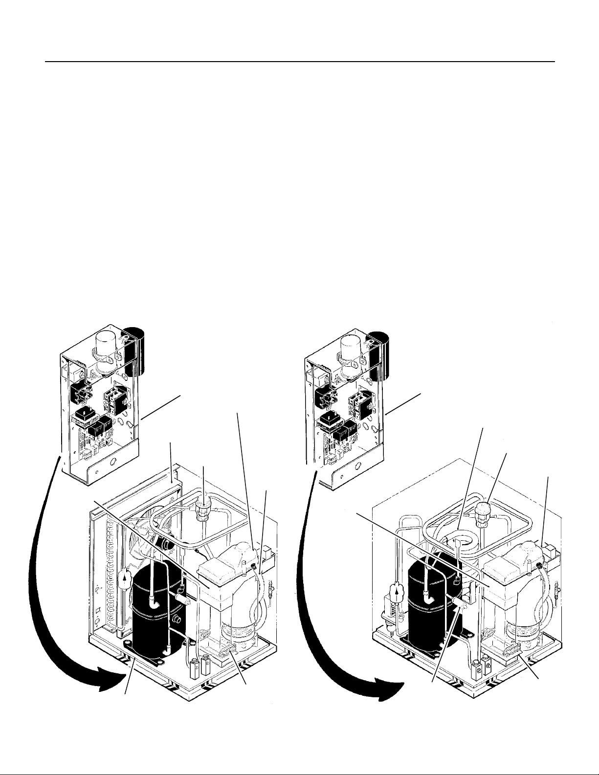
NME650 & FME800
COMPONENT DESCRIPTION
Control Box:
Contains th e el e c t r i c al c o nt r ol s th at
operate the machine.
High Pressure Cut Out Switch
: A manual reset
switc h sensing the hi g h si d e r efrigeration press ur e .
It is set to shut the machine off if the discharge
pressure should ever exc eed 450 psig.
Compressor:
Reservoir:
The ref r igerant vapor pump.
Float operate d, it maintains the water
level i n th e ev a po r at or at a constant le vel, it also
contains the water level sensor.
Water Level Sensor:
Senses if there is water in
the reservoir to make ice out of. Will shut the
machine off it there is no water.
AIR COOLED
Ice Discharge Chute
: Directs the ice pro duced
by the evaporat or into the st or age bin.
Ice Level Sensor:
An electronic “eye”, it senses
the pres ence of ice i n the bottom of the ice
discharge chute. Operates to turn the ice machine
on and off automatically as the level of ice in the
bin chan ges.
Gear Motor:
An oil filled, speed reduction
gearbox, driving the auger .
Condenser:
Air or water c oo l ed , w he r e th e he at
remov e d i n i ce m aking is dis c ha r ged.
Expansion valve
: The refrigerant metering
device.
WATER COOLED
ICE CHUTE
CONTROL BOX
CONDENSER
EXPANSION
VALVE
RESERVOIR
DRAIN
TUBE
CONTROL BOX
CONDENSER
EXPANSION
VALVE
RESERVOI R
ICE CHUTE
COMPRESSOR
ICE LEVEL
SENSORS
February 1997
Page 10
HIGH
PRESSURE
CUT OUT
ICE LEVEL
SENSORS
Page 11

COMPONENT DESCRIPTION: Control Box
NME650 & FME800
Contactor:
connecting the compressor to the power supply.
Circuit Board
The circuit board receives input signals from
several sensors and translates them to control the
elect r i cal po w er su pply to the va ri ou s lo ad s.
The sensors include:
Electri c eyes to check the ice level in the bin.
•
A thermistor to check the water level in the
•
reservoir.
Amp draw of the gearmotor.
•
A definite purpos e co ntactor
ON/OFF SWIT C H
LOW
PRESSURE
CUT OUT
SWITCH
The loa ds include:
Compr essor cont ac t or
•
Fan motor
•
Auger dri ve motor
•
Low Pressure Cut Out Switch
A manual reset control that shuts off the ice
machine when the low side pressure drops below
a prese t point, 0-4 ps ig.
Potent ia l Rel ay
On/Off Switch:
: The compressor start relay.
Manual control for the machine.
POTENTIAL
RELAY
TRANSFORMER
CIRCUIT
BOARD
CONTACTOR
"No Water" Light.
Glows When Water
Reservoir is Dry
"Bin Empty" Light.
Glows When Ice Level Is
Below Electric Eyes
February 1997
Page 11
Page 12

NME650 & FME800
COMPONENT DESCRIPTION
Evaporator
water an d c o nt ai n i ng a wa te r se al and auger.
Auger:
it push es th e i ce crystals up to th e to p of t he
evapor ator.
Water Seal :
rotat ing with the au ge r , th e bo ttom half stationar y,
the sealing action being where the two seal "faces"
meet.
: A refrigerated vertical tube filled with
A solid sta inl e s s s te el do ub l e s p i r al auger,
A two part "face" seal , the top half
Ice Swee p
with the auger to "sweep" the ice int o the ice chute.
Breaker:
of the extra water is squeezed out of it before it is
discha r ge d i nt o the bin.
Motor:
Thrust Bearing:
evaporator, the auger is thrust down, and pressure
from the auger thrust is taken up by this bearing.
: A plastic cap with "fingers". It revolves
Where th e i ce i s com p r essed and muc h
A motor tha t dr iv e s the gear reduc e r .
As the ice i s pu s he d up the
ICE SWEEP
BEARING
BREAKER/DIVIDER
WATER
SEAL
AUGER
EVAPORATOR
February 1997
Page 12
MOTOR
Page 13

ELECTRICAL SEQUENCE:
Refer the wiring diagram as needed.
If the machine is switched off at the master switch,
but is ot he r w i se r ea dy to go, switching the m aster
switch to on does the following:
The bin em pty light on the circuit board goes on
•
There is a 15 sec o nd del a y
•
If there is enough water in the reservoir, the
•
circuit board will allow the machine to start up.
Start up consists of:
The compressor relay and auger motor relay
•
become energized, connecting power to the
windings of the auger motor.
The auger m ot or starts, an d th e ce ntrifuga l
•
switch closes, connecting power to the
compressor contactor coil.
The cont actor is ener gized, connecting power
•
to the compressor, and the compressor starts.
As ice goes past the ice level sensors, the bin
•
empty light will stay on, and the machine will
continue to run, unless the ice stays between
the sensors for more than 15 seconds (bin full).
At that point, the bin empty light goes out, and
the machine shuts down.
NME650 & FME800
Shut Down consists of:
The compressor relay opens.
•
The compressor contactor opens
•
The compressor stops
•
The auger motor is run by the circuit board for 2
•
more minutes, clearing out ice in the
evapor a to r , and then
The auger m otor relay op en s , and the auger
•
motor stops.
If the ice level sensor is clear (bin empty) for more
than 15 seconds, the machine will start up again.
Anothe r pur p ose of the circuit boar d is to tu r n th e
machine off if there is not enough water in the
machine.
When the water level in the reservoir falls
•
below the water level sensor, the machine will
“shut down”
When the water refills the reservoir, the
•
machine will start up again.
Separate from the circuit board:
If the high pressure control (cut out sw i tch)
•
opens, the machine will stop immediately
(through the relays on the circuit board). It must
be manual ly reset at the control.
If the low pressure control (cut out switch)
•
opens, the machine will stop immediately
(through the relays on the circuit board). It must
be manual ly reset at the control.
The mast er s w it c h i s t he ma nu al co ntrol for the
•
complete machine, but it is not a service
disconnect.
February 1997
Page 13
Page 14

NME650 & FME800
OPERATION: Water
Water enters the machine through the 3/8" male
flare at the rear of the cabinet, goes to a strainer
and then to the water reservoir which it enters
through the float valve. The wat er then goes out
the bottom of the reservoir tank to the bottom of
the evap or a tor.
Water Level: The correct water level should be
checked when the machine is making ice. Check the
water level in the reservoir and compare it to the
horizontal line molded into the side of the reservoir.
The correct level should be between
1
" below the line. If needed, bend the float arm up or
⁄
4
down to adjust the water level.
EVAPORATOR
DRAIN
RESERVOIR
1
" above and
⁄
8
Reserv oi r overflow or evaporator condensation is
routed to the dra i n. Water cooled mode l s have a
separate water circuit for the cooling water: it
enters th e fitting at the re ar , goe s t o th e water
regulating val ve, then to the water cooled
conden s er an d do w n the drain.
STRAINER
WATER LEVEL
EVAPORATOR
DRAIN
ICE
CHUTE
WATER SCHEMATIC
February 1997
Page 14
Page 15

OPERATION: Refr igeration
NME650 & FME800
Beginni n g at the compr es s or , the refrig er ant is
compressed int o a high temper at ur e gas. The
disch ar ge line directs th i s gas to the co ndenser . At
the cond en s er ( air or w at er cooled) th e ga s is
cooled by either air or water and it then condens es
into a li qu i d. Th is hi g h pr e ss u r e l iquid then goe s
through the liquid line to the expansion val ve.
The ther m ostatic expansio n va l v e m et er s liquid
refri ge r an t i nt o the evapora t o r , th e vol u m e of liquid
refrigerant depending upon the temperature of the
evaporator.
CONDENSER
LIQUID
LINE
FAN
MOTOR
DISCHARGE
At the evaporator, the refrigerant enters an area of
relatively low pressure, where it can easily "boil
off" or evaporate. As it evaporates, it absorb s heat
from the evaporator and whatever is in contact
with it (such as the water inside it). After the
evaporator, the refrigerant, now a low pressure
vapor , go es th r ou gh the s uction line ba c k to
compressor, where the cycle is repeated.
Refrigeration Schematic
SUCTION LIN E
LINE
EVAPORATOR
OPERATION: Performance
Typical Low Side Pressure
Air Cool ed: 34 - 38 PSIG
•
Water Cooled: 32 PSIG
•
Typical Discharge Pressure
Air Cooled: 220 - 300 PSIG
•
Water Cooled: 245 PSIG
•
Typical Compressor Amp Draw
8 -9
•
Typical Gearmotor Amp Draw
3.1 to 3.5
•
Superheat
5 - 7 degrees
•
High Pressure Cut Out
450 PSIG
•
THERMOSTA T IC
EXPANSION
VALVE
COMPRESSOR
Low Pressure Cut Out
0 - 4 PSIG
•
Fan Motor Watts
35 Watt
•
Refrigerant Charge
Air Cooled: 24 ounces HP62
•
Water Cooled: 20 ounces of HP62.
•
GEAR
MOTOR
February 1997
Page 15
Page 16

NME650 & FME800
CLEANING & SANITIZING
A Scotsman Ice System represents a siz a ble investment of time and money in an y c om pany’s business. In
order to receive the best return for that investment, it MUST receive periodic maintenance.
It is the USER’S RESPONSIBILITY to see that the unit is properly maintained. It is always preferable, and
less costly in the long run, to avoid poss ible do wn time by keeping it clean; adjusting it as needed; and by
replacing worn parts before they can cause failure. The following is a list of recommended maintenance
that will help keep the machine running with a minimum of problems.
Mainte na nce and Clea ning should be sc h ed ul e d at a
Note: Electrical power will be ON when doing
in place cleaning .
minimum of twice per year.
ICE MAKING SYSTEM: In place cleaning
1. Check and clean any water treatment devices,
if any are installed.
2. Remove screws and the fron t and top pa nels.
3. Move the ON-OFF switch to OFF.
4. Remove al l the ice from the stor age bin.
5. Remove the cover to the water reservoir and
block the float up.
6. Drain the water reservoir and freezer assembly
using the drain tube att ached to the freezer water
inlet. Return the drain tube to its normal upright
position and replace the end cap.
7. Prepare the cleaning solution: Mix eight
ounces of Scotsma n Ice Machine Cleaner with
three quarts of hot water. The water should be
between 90-115 degrees F.
Scotsman Ic e M a chine
Cleaner contains acids.
These compounds may
cause burns.
If swallowed, DO NOT
induce vomiting. Give
large amounts of water
or milk. Call Physician
immediately. In case of
extern al co ntact, flu sh
with water.
KEEP OUT OF THE
REACH OF CHILDREN.
8. Slowly po ur th e cl ea ni n g solution in to the wa te r
reservoir until it is full. Wait 15 minutes, then
switch the master switch to ON.
9. As the ice m aker begins to use water from the
reservoir, continue to add more cleaning solution
to maintain a full reservoir.
10. After all of the cleaning solution has been
added to the reservoir, and the reservoir is nearly
empty , sw i tch the master sw i t ch to O FF .
11. Drain the water reservoir and freezer assembly
using the drain tube att ached to the freezer water
inlet. Return the drain tube to its normal upright
posit i on and re pl a ce the end cap. Was h an d r i nse
the water reservoir.
Sanitizing:
To sanitize, use an approved sanitizing solution or
mix one ounce of household bleach to 2 gallons of
warm (95
using the sanitizer solution in place of the cleaning
solution.
12. Remove the block from the float in the water
reservoir.
13. Switch the master switch to ON
14. Continue i ce making for at least 15 minutes, to
flush ou t any cleaning solution.
///////////////////////////////////////////////////////////////////////////////
DO NOT USE any ice produced from the
cleaning solution.
Be sure no ice remains in the bin.
////// ////////////////////////////////////////////////////////////////// //////
15. Remove all ice from the storage bin.
16. Add war m w at er to the ice storage bi n and
thoroug hl y wash and ri ns e al l sur faces within the
bin.
17. Sanitize the bi n i nt er i o r with an approve d
sanitizer using the directions for that sanitizer.
18. Repl ace the panel s.
o
F.-115oF.) water. Repeat steps 8-11
February 1997
Page 16
Page 17

MAINTENANCE AND CLEANING
1. The bin control uses devices that sense light,
therefore they must be kept clean enough so that
they can “see”. At least twice a year, remove the
bin control sensors from the base of th e ice chute,
and wipe the inside clean, as illustrated
2. The ice machine s e nses water l ev e l by a pr obe
located in the water reservoir. At least twice a
year, the probe should be removed from the
reservoir, and the tip wiped clean of mineral
build-up.
ICE LEVEL SENSORS:
SLIDE TO REMOVE
.
NME650 & FME800
4. Check and tighten all bolts and screws.
PULL UP TO
REMOVE PROBE
RESERVOIR
CLEAN THE
WATER LEVEL
PROBE
CLEAN THE
LIGHT SENSO RS
3. The bear i n g i n th e br e aker should
also be checked at leas t
per year
A. Check the bearing by:
•
•
•
•
•
•
Inspect the assembly, looking for wear.
See Removal and Replacement to replace
bearin g or seals. Reverse to reas s em b l e.
.
switching the machine OFF
removi n g the ice chut e cover
unscrewing the ic e s weep
removing the water shed
unscrewing the breaker cover.
unscrewing the auger stud
two times
Moving Parts Hazard.
Rotating parts can cause
person al i njury.
Disconnect electrical
power be fo r e be gi n ni n g.
///////////////////////////////////////////
CAUTION: THE TIP IS
MADE OF GLASS
//////////////////////////////////////////
ICE SWEEP
BREAKER
COVER
FME Components
Shown, NME similar.
February 1997
Page 17
Page 18

NME650 & FME800
MAINTENANCE: Air Cooled
Hazardous Moving
Parts.
Moving fan blade can
cause personal i njury.
Disconnect electrical
power be fo r e be gi n ni n g.
5. Clean the air cooled condenser.
The air flow on this model is from front to back, so
the inside of the machine will have to be available
to clean the air cooled condenser. Use a vacuum
clean er or c oil c leaner if ne ed ed . D o N OT us e a
wire brush.
A. Disconnect electrical power, and remove the
filter . The filter m ay be cleane d or replaced.
B. Clean the condenser: the condenser may
appear to be clean on the surface, but it can still
be clog ge d i nt er n al l y. Check wit h a fl a sh light from
the front to see if light can be seen though the
condenser fins. Reverse to reassemble.
Step 2: Remove the top portion of the fan shroud.
Step 1: Remove the top panel.
Step 3: C lea n the conden ser .
February 1997
Page 18
Page 19

MAINTENANCE AND CLEANING: Auger
After the auger has been removed, allow the auger
to dry: if the auger is not bright and shiny, it must
Hazardous Moving
Parts.
Movin g au ge r c an cause
person al i njury.
Disconnect electrical
power be fo r e be gi n ni n g.
be cleaned.
Clean the auger and evaporator as required. DO
NOT HONE THE EVAPORATOR.
7. Repl ace the wat er seal.
8. Reverse to reassemble.
NME650 & FME800
In some areas, the water supply to the ice maker
will contain a high concentration of minerals, and
that will result in an evaporator and auger
becoming coated with these minerals, requiring a
more frequent removal than twice per year. If in
doubt about the condition of the evaporator and
auger, the auger can be r em o v ed so the parts ca n
be inspected.
Note: Water filters can filter out suspended solids,
but not dissolved solids. “Soft” water may not be
the complete answer. Check with a water
treatm en t s p eci a l i st re ga r di n g w at er treatment.
For more information on removal of these
parts, see REMOVAL AND REPLACEMENT.
1. To remove the auger, remove the front and top
panels.
2. Push bail clamp back from the top of the chute
cover.
Bail Clamp
FME Components
Shown, NME similar.
ALLEN
SCREWS
BREAKER &
BEARING &
AUGER
ASSEMBLY
Chute Cover
NME Components
Shown, FME similar.
Assembled Chute
and Evaporator
3. Unscrew and remove ice sweep.
4. Remove 4 allen screws holding breaker to
evaporator.
5. Pull up to remove auger.
Breaker Cover
February 1997
Page 19
Page 20

NME650 & FME800
SERVICE DIAGNOSIS: Condition - No Ice Being Produced
STATUS:
Check:
A.
Check: The
B.
Check: The reset switches, ( high and low pressure): depress and release each switch. If the
C.
Voltage
to the unit, restore it if there is none. Compare to the nameplate.
master switch
, switch ON if off.
NOTHING OPERATES
still does not start, check the high and low side pressures.
Check the
D.
Low refrigerant charge
•
The auger not turn ing
•
Restricted system
•
TXV not opening
•
1. Check the low si de pressur e, the low pressur e cut out opens at pre ss ure below 4 psig.
If open , r eset and:
drier, evacuate, and weigh in the nameplate charge. If, with added charge, the unit
repla ce it. Replace the drier, evac uate, an d weigh in the namep late cha r ge.
low pressure cut out,
a. Check if the
Check for internal damage, repair an d replace in the mac hine.
b. Check for low charge, add some refrigerant, if the unit will operate,(normal
low side pressure being about 32-34 psig) stop and look for a leak, repair, replace the
does
not
Check for a restricted system, replace the drier, evacuate, and weigh in a
nameplate charge.
Check for a
auger
operate:
if closed, go to
is turning, if it is not, remove the
Thermostatic Expansion Valve
if open, it could be due to
E;
:
gearbox
that does not open , if defective,
and:
Check the
E.
1. The pressure control opens at 450 psig.
and obse r ve: on wate r cooled, that water soon be gins to flow from the condenser drain;
or, on air cooled, that the fan is forcing air through the condenser. If the unit trips out on
pressures below 45 0 psig, repl a c e th e control. If the pressures ri se above the trip out
point, an d th e un i t s hu ts down:
fil t er . I f th e ai r flow is poor be ca us e of th e i nstallat i on , ad v is e the us er th at t he unit
should be moved, or the air around it kept cooler.
. Check the
F
high pressure cut out,
a. Check for adequate water flow on water cooled, if adequate, clean the interior
of the condenser. If the pressures are still too high replace the water regulating valve.
b. Check for adequate air fl ow on air co oled. Clean the condenser and (if us ed) the
Check the fan motor for tight bearings and proper rotation.
Check that the fan blade s are clean, and the fan secur e to the fan motor s haft.
water level
1. Resto r e/ adjust wat er l eve l . See the next step.
in the reservoir. The machine must have enough water in the reservoir.
if closed go to F; if open check:
Check
the high side pressure, reset the control,
February 1997
Page 20
Page 21

NME650 & FME800
SERVICE DIAGNOSIS: Condition - No Ice Being Produced
NOTHING OPERATES
. Check: The gear
G
motor
STATUS:
, the motor must turn at full speed or the compressor contactor will not
pull in. If the motor will not turn fast enough, check the auger and evaporator for scale build up.
If no power to the motor:
Check: The
shoul d be OF F
1. If the
side should be a t l ine voltage. If the line side has the correct voltage and the
2. If the tr ansfor m er is good, and the
3. If the transformer is fine, and the “no water” light is ON, check the
MORE INFORMATION ON THE TESTER CAN BE FOUND AT THE END OF THE MANUAL.
indicator lights
.
bin empty
a. Tran sformer “load” side should have 12 to 15 volts. If not, check the “line” side. The lin e
load side does not, replac e the transformer .
a. Remove sensors by sliding them sideways out of the ice chute. Visually inspect them,
clean if ne ed ed.
b. Look thr o ug h the ice chut e “ ey e” ho l e fo r so mething blo cki n g the ice chut e.
c. If the unit still does not run, replace the ice level sensors.
d. If the bin empty light is still OFF, check the
a. Check the water level in the
b. Remove the water level sensor from the reservoir and clean the tip if dirty.
CAUTION: THE TIP IS MADE OF GLASS
c. Replace the water level sensor. If the no water light is still on, check that the
"water sen" plug is firmly plugged into the circuit board.
d. If the no water light is still on, check the circuit board:
and
See the instructions at the end of the manual. If the machine operates with the
tester, and not by itself, the ice level sensors should be replaced.
1. Unplug the “water sen” connector from the circuit board.
2. Plug “w a te r se n” co nnector fro m the S co ts m a n El e ctronic Co nt r ol te ster into
the circuit board.
on the circuit board, the
no water
a. Move the water switch on the tester to “no water” and the no water light
on the c i rcuit board should go on. If not, replace the board.
b. Move the water switch to the “water” position, the no water light should
go off and after 15 seconds , the machine should start, if not,
repla ce the circuit board.
If the machine works with the tester, and not by itself,
repla ce the wat er level sensor.
lights are off, check the
bin empty
reservoir,
bin empty
light is OFF, check the
restore if low. If the water level is ok:
light sh ould be ON , the
transformer
circuit board
.
ice level senso rs
.
water leve l se nso r .
no water
.
light
Check the gearmotor relay on the circuit board.
If the bin empty light is on, and the water level light is off, there should be power (after 15 seconds) at the
com. terminal of the gearmotor relay, if not, replace the circuit board.
February 1997
Page 21
Page 22

NME650 & FME800
SERVICE DIAGNOSIS: Condition - No Ice Produced
STATUS:
Check the
A.
The relay is on the circuit board, if it does not supply power to the contactor coil, the
compressor will not run.
1. Check for po w er at t he contactor co i l, i f none:
2. Check the contactor coil. If the co il is open, replac e the con tactor.
3. Check th e auger dri ve motor ce ntrifugal switch. If, when the drive motor is running,
contac t 4 (b l ac k wi r e re m oved) has no power, and all of the above switches hav e be en
checked, replace the centrifugal switch, or the drive motor.
4. If the comp r essor rela y on the circuit boa r d ha s pow e r on th e N O co ntact, but no t on the COM con tact,
replace the circu i t bo ar d .
compressor relay.
Check for power at the compressor relay at the circuit board.
a.
If there is power at the relay, but none at the contactor coil ,
GEARMOTOR OPERATES, COMPRESSOR DOES NOT
Check for an open wire be tween the relay an d the contactor.
B. Check the compresso r
1. Check the compressor start relay.
2. Check the start capacitor.
3. Check the wind ings of th e compres sor for open windings or shorts to groun d.
Replace those items found defective.
February 1997
Page 22
Page 23

NME650 & FME800
SERVICE DIAGNOSIS: Condition - Low Ice Production
STATUS:
Check the air cooled condenser for dirt. Clean as required. Check the head pressure on water
A.
EVERYTHING IS OPERATING
cooled. Adjust as required. If the head pressure is very high:
1. Air co oled. Check for high air tempe r atures, or re s tr ictive air fl ow . Co r r ect as needed .
2. Water c o ol e d. Ch ec k f or hi g h w ater temper atures, or l ow w ater pressure.
Correct as needed.
3. The refrigerant may contain non condensable gases, purge, evacuate, and recharge per nameplate.
Check the evaporator
B.
1. Clean the evaporator, the mineral build up will adversely affect the ice machines production.
2. Check the evaporator for water leaks, rep lace the water seal if found to be leaking .
3. Check the low side pressure; normal is about 32-34 psig. If low, assume a refrigerant leak,
locate, r ep ai r an d r ec ha r ge .
If no leak, the TX V may be restricted , defective or not adjust ed proper ly. If needed,
replace the TXV, evacuate, and rechar ge per nameplate.
4. Check th e i nsu l at i on on th e evaporato r . It sho ul d be dr y , w i th no w et spots or frost.
If the ins ulatio n has failed: replac e the evaporator or add extra insulati on in the form
of foam tape to the eva p orator.
Check the compressor.
C.
1. The compressor may be inefficient.
a. Check the amp draw, if low change the compressor.
b. if the amp draw is normal, pinch off the suction line to check the pull down capability
of the comp r essor. The co m pr e s sor should pu l l dow n to 25 inches of vac u um an d ho l d
there for three to five minutes.
.
February 1997
Page 23
Page 24

NME650 & FME800
REMOVAL AND REPLACEMENT: Bin Controls
BIN CONTROLS (Ice Level Sensors)
1. Disconnect electrical power.
2. Remove front pa nel.
3. Remove control box cover.
4. Locat e i c e ch ute, at the ba se of the chute , i n
front of an d behind it are two plastic bin control
mounts.
5. Slide each bin control to the left, and in the
contr ol bo x , di sconnect the elect r i ca l le ad s
connecting the bi n co ntrol to the cir c ui t board.
6. Reverse to reassemble, be certain that the bin
contro ls are aligned so that the ice level sensors
are visible (centered) through the holes in the ice
chute.
ICE
CHUTE
SLIDE BIN
CONTROLS IN
AND OUT
RESERVOIR
1.Shut off water supply.
2. Remove front pa nel.
3. Remove reservoir cover.
4. Disconnect water inlet tube from reservoir inlet
fitting.
5. To remove float valve, push in on "Locking Tab"
as shown and pull valve up.
Note: The plun ger/seat is available as a separate
part.
6. To remove reservoir, pull up and remove water
sensor.
7. Disconnect w ater outlet tubes.
8. Remove the two screws holding reservoir to
bracket.
9. Remove reservoir from ice machine.
10. Reverse steps 1-9 to reassemble.
Float Valve
Plunger &
Valve Seat
Locking
Tab
February 1997
Page 24
Page 25

NME650 & FME800
REMOVAL AND REPLACEMENT: Bearing And Breaker
c. Unsc rew 4 al l e n he ad ca p sc r e w s ho l di n g
breake r to evaporator.
Hazardous Moving
Parts.
Movin g au ge r c an cause
person al i njury.
Disconnect electrical
power be fo r e be gi n ni n g.
Note: Removal of the auger, water seal,
evapo r ator and gearmotor must begi n at the to p of
the assem b l y .
To Remove the Breaker Bearing Assembly:
1. Remove panels and disconnect electrical power.
2. Pull the bail clamp off of the chute cover.
Unscre w thr ee studs and remove ic e chute cover.
3. Unscrew and remove ice sweep.
4. Remove insulation halves from outside of ice
chute l i ft up and remo ve i c e ch ut e.
5. The bre aker may be re m ov ed f r om the auger
and evaporator without disturbing the auger.
a. Unscrew breaker cover from breaker (left hand
threads)
b. Unscrew auger stud from top of auger.
See page 19.
d. Lift up , an d r em o ve breaker/ be ar i n g assembly
from auger & evaporator.
6. Service the bearing. Check for rust, rough spots
and damage.
a. The bear ing is pressed into the break er, to
remove the bearing and replace it an arbor press
is need ed .
b. Replace lower seals before installing new
bearin g i n br e aker.
Note: seals must be pressed in with a tool pushing
against the outer edge only, they will not install by
hand.
Replac e parts as re qu i red. Re-grea s e be ar i n g w it h
Scotsman part no. A29123-001 bearing grease.
Replac e top seal, and c h eck the o-ri ng s, r eplace if
cut or torn.
7. Reverse to reassemble: specific tools and
materi a l s ar e re qu i r ed t o ins t al l pr o perly.
a. Add food grade gr ease such as Scotsman part
number 19-0569-01 to th e seal area before
installing on the auger.
b. Check the seal to shaft ar eas for cu ts, or rough
spots: none are permitted.
FME Components Shown, NME si m ilar.
Step 5-a Step 5-b Step 5-c and Step 6
BEARING
ICE
SWEEP
AUGER
STUD
BREAKER
COVER
SEALS
February 1997
Page 25
Page 26

NME650 & FME800
REMOVAL AND REPLACEMENT: Auger
c. Unsc rew 4 al l e n he ad ca p sc r e w s ho l di n g
breake r to evaporator.
d. Lift up & re m ove breake r fr om evaporato r .
Hazardous Moving
Parts.
Movin g au ge r c an cause
person al i njury.
Disconnect electrical
power be fo r e be gi n ni n g.
To Remove the Auger:
Turn off the wat er to the ma chine, and unclip the
evapor ator drain hose, pull it down and drain the
evaporator into the bin or a container.
1. The top panel must be removed.
2. Remove bail clip and remove ice chute cover.
3. Unscrew ice sweep.
4. Remove ice chute body.
5. The auger and breaker/be ar ing may now be
removed as an assem bl y.
a. Unscrew 4
allen head cap
screws holding
break er to
evapor ator.
b. Lift up on
break er an d
remove auger
from
evaporator.
Note: If the
auger is
BREAKER
AND AUGER
ASSEMBLY
FME Components
Shown, NME similar.
stuck, the
breaker must
be removed
from the
auger.
The bre aker
may be
removed from
the auger and
evaporator without disturbing the auger.
a. Unscrew breaker cover from breaker (left hand
threads)
b. Unscrew auger stud from top of auger.
e. If the auger is stuck use a slide hammer type
pulle r to pull on the auger a t the threaded hol e.
The siz e of t ha t ho l e i s 5/ 8" - 18 .
Inspect the auger, the critical areas of the auger
are:
1. The auger body. It should be clean and
shining. Sometimes an auger will appear clean
when wet, but after it is dry it will be seen to be
stained. Scrub the auger with ice machine cleaner
and hot water.
////// // // // // // // // ////////////WARNI NG/ ////////////////// ///////////
Ice machine cleaner is an acid. Handle it with
extreme care, keep out of the reach of children.
///////////////////////////////////////////////////////////////////////////////
2. The water seal area. Because the auger has
been removed, the water seal will have to be
replaced. Remo ve the water seal top half from the
auger, and inspec t th e au ge r for m i ne r al s clean as
required.
SLIDE HAMMER
PULLER
THREAD INTO THE
AUGER HERE
February 1997
Page 26
Page 27

REMOVAL AND REPLACEMENT: Water Seal
To Remove the Water Seal:
(Assum i n g al l s t ep s to r em o v e the auger hav e
been performed.)
1. The gearmotor/evaporator assembly will have to
be exposed.
2. Remove the 4 hex head c a p s cr e w s hol d i ng the
evapor a to r t o th e ge ar m o to r ass e m bl y. Lift the
evapor a to r up an d off of the gea r motor.
3. Remove the snap ring or wire retainer from the
grove under the water seal.
4. Pull or dr ive out the low e r hal f of the water sea l .
REMOVAL OF THE WATER SEAL
To Replace the Wate r Seal:
1. Lubricate the w ater sea l with water, and push
the water s e al into the bottom of the evaporator
slightly past the grove for the snap ring.
2. Replace the snap ring and pull the water seal
down agai n s t it.
3. The part of the water seal that rotates with the
auger mu s t al so be re pl a c e d. Rem o ve the old part
from the auger and clean the m ounting area.
4. Place a small bead of food grade silastic sealant
(such as 732 RTV or Scotsman par t number
19-0529-01) on the area of the auger where the
water seal is to be mo un te d.
REPLACING THE WATER SEAL
NME650 & FME800
WATER SEAL
RETAINING
RING
PLACE FOOD
GRADE SEALANT
HERE
5. Carefully push the water seal (rubber side
agains t the auger should er an d th e s il a s ti c.)
////// // // // // // // // ////////////CAUTI ON/ // // // ////////// /////////////
Do not get an y s i lastic onto the f ac e of t he seal .
////// // // // // ////////////////// ////////////////////////// ////////////////////
6. Allow the auger and seal to air dry until the
silastic is dry on the surface.
7. If the original water seal was leaking, it would be
a good idea to inspect the interior of the gearmotor.
February 1997
Page 27
Page 28

NME650 & FME800
REMOVAL AND REPLACEMENT: Evaporator
To Replace the Evaporator:
(Assum i n g al l th e steps for rem o v a l of th e th r ust
bearin g, breake r , au ge r , an d w at er s ea l have been
performed.)
1. Recover the refrigerant from the ice maker.
2. Unsweat the refrigerant connections:
a) At the thermostati c expansion valve outlet.
/
////////////////////////////////CAUTION//////////////////////////////
Heat sink the TXV body when unsweating or
resweating the adjacent tubing.
////// ////////////////////////////////////////////////////////////////////////
b) At the suction line at the joint about 3" from the
evaporator.
3. Remove the evaporator.
4. Unsweat the drier from the l iquid line.
5. After installing a new water seal in the new
evaporator (see “To Replace the Water Seal”)
sweat in the new evaporator at the old tubing
connections.
6. Install an new drier in the liquid
line.
7. Evacuate the system until
dehydr a te d, then weig h in the
namepl at e c h ar g e. Check for le aks.
ICE CHUTE
8. Instal l auger, br eaker , br eaker be aring
assembly, and ice discharge chute in reverse
order of di s a ss e m bl y. See “ T o R ea ss e m bl e
Evapor ator and Au ger”
To Reassemble the Evaporator and Auger
1. After the gearmotor has been inspected, fasten
the evap or a to r to th e ge ar m ot or , be sure that th e
number of s h i m s in di c ated on the gear case cover
is in place between the gearcase cover and the
drip pan gasket. Torque the bolts to 110 inch
pounds.
2. Lower the auger into the evaporator barrel,
slightly turning it to match up with the drive end.
Do Not Drop Into the Evaporator.
3. Complete the reassembly by reversing the
disassembly for the breaker & thrust bearing
assembly.
ICE SWEEP
EVAPORATOR
BEARING
BREAKER
AUGER
NME Components
Shown, FME similar.
February 1997
Page 28
Page 29

REMOVAL AND REPLACEMENT: Gearmotor
Note: The gears and bearings are available only as
pressed together sets.
Electrical Shock Hazard.
Electrical shock can
cause personal injury.
Disconnect electrical
power before beginning.
NME650 & FME800
To Remove and Repair the Gearmotor
Assembly:
(Assuming that the procedures through
removal of the water seal have been
performed.)
1. Remove the electrical wires from the gear
drive motor.
2. Unscrew the 4 cap screws holding the
gearmotor to the base of the machine.
3. Remove the gearmotor from the
icemaker.
COVER &
OUTPUT GEAR
ASSEMBLY
Bench te s t th e ge ar m o tor, check f or
oil leaks, noise, and amp draw.
To Inspect the gearmotor.
A) Remove the cap screws holding
the gearmotor case halves together
and pry the two cases apart.
B) To lift off the cover, lift up until you
can feel internal contact, then pull the
cover towards the output gear end,
and then lift the cover (with drive
motor attached) up and away from the
gear motor case.
Note: The gearcase cover, output
gear, bearings and output shaft are
a pressed together assembly.
Replace as a unit.
C) Inspect the oil, gears, and
bearings. If the oil level and condition
is acceptable, quickly check the gears
and bearings. They are likely to be
fine if the oil is.
If there is evidence of water in the oil
(rusty bearings and gears; the oil
having a creamy white appearance;
oil level too high) carefully inspect the
bearings and gears. If in doubt about the condition
of a part, replace it. The oil quantity is 14 fluid
ounces, do not overfill.
WATER SHED
CENTRIFUGAL
SWITCH
ROTOR BEARING
SEAL
D) After replacing parts as required,
(if any) reassemble the gearcase.
The two smaller gears and the oil
should be in the lower case, the
output gear will be with the cover. As
you lower the cover onto the lower
case, the cover will have to be
moved closer to the second gear
after the output gear has cleared the
second gear top bearing.
E) After the case is together, and the
locating pins are secure in both ends,
replace all cap screws.
GEAR CASE
Bench test the gearmotor, check for oil leaks,
noise, and amp draw.
February 1997
Page 29
Page 30

NME650 & FME800
REFRIGERATION SERVICE: R-404A
THIS ICE MACHINE USES R-404A (HP62)
REFRIGERANT AND POLYOLESTER
COMPRESSOR OIL.
DO NOT USE MINERAL OIL IN THIS
REFRIGERATION SYSTEM.
R-404A is a "Near Azeotrope", and therefore
•
liquid charging is required.
When the system is serviced, a special liquid
•
line dryer is required.
Polyolester oil absorbs water very easily, and
•
therefore when the system is opened for
service, it must be re-sealed as soon as
possible (15 minutes maximum).
Special leak detection equipment is required to
•
locate small refrigerant leaks. Usually a leak
detect or c a pa bl e of detecting a H al o ge na ted
refrigerant or HFC-134A will work. Check with
the leak detector manufacturer if in doubt.
As with any other refrigerant, do NOT mix HP62
•
with pressurized air when leak testing.
Evacuate to 300 m icrons
•
Recover, reclaim or recycle refriger ant
method chosen is up to the service com pany. Any
refrigerant placed into a Scotsman ice machine
must meet ARI spec 700-88. Reclaim programs
are avail able through mos t refrigerant wholesalers.
Access Valves:
Remove the cap from the stem, use a 3/16" allen
wrench to check that the valve is CLOSED. The
remove the core cap.
Close t he va lve and repla ce th e caps w hen t he
job is finished. The valve must be closed and
the caps must be on or the valve will leak.
To use the access valves:
. The
VAPOR VAPOR
TEMP. PRESSURE TEMP. PRESSURE
(DEG F) (PSIG) (DEG F) (PSIG)
-20 . . . . . 17 70 . . . . . . 146
-18 . . . . . 18 72 . . . . . . 150
-16 . . . . . 20 74 . . . . . . 155
-14 . . . . . 21 76 . . . . . . 161
-12 . . . . . 23 78 . . . . . . 166
-10 . . . . . 24 80 . . . . . . 171
-8 . . . . . . 26 82 . . . . . . 177
-6 . . . . . . 28 84 . . . . . . 182
-4 . . . . . . 29 86 . . . . . . 188
-2 . . . . . . 31 88 . . . . . . 194
0 . . . . . . 33 90 . . . . . . 200
2 . . . . . . 35 92 . . . . . . 206
4 . . . . . . 37 94 . . . . . . 212
6 . . . . . . 39 96 . . . . . . 219
8 . . . . . . 41 98 . . . . . . 225
10 . . . . . . 43 100 . . . . . 232
12 . . . . . . 46 102 . . . . . 239
14 . . . . . . 48 104 . . . . . 246
16 . . . . . . 50 106 . . . . . 253
18 . . . . . . 53 108 . . . . . 260
20 . . . . . . 55 110 . . . . . 268
22 . . . . . . 58 112 . . . . . 275
24 . . . . . . 60 114 . . . . . 283
26 . . . . . . 63 116 . . . . . 291
28 . . . . . . 66 118 . . . . . 299
30 . . . . . . 69 120 . . . . . 307
32 . . . . . . 72 122 . . . . . 316
34 . . . . . . 75 124 . . . . . 324
36 . . . . . . 78 126 . . . . . 333
38 . . . . . . 81 128 . . . . . 342
40 . . . . . . 85 130 . . . . . 351
42 . . . . . . 88 132 . . . . . 360
44 . . . . . . 91 134 . . . . . 370
46 . . . . . . 95 136 . . . . . 379
48 . . . . . . 99 138 . . . . . 389
50 . . . . . . 102 140 . . . . . 399
52 . . . . . . 106 142 . . . . . 409
54 . . . . . . 110 144 . . . . . 420
56 . . . . . . 114 146 . . . . . 430
58 . . . . . . 118 148 . . . . . 441
60 . . . . . . 123 150 . . . . . 452
62 . . . . . . 127 152 . . . . . 464
64 . . . . . . 132 154 . . . . . 475
66 . . . . . . 136 156 . . . . . 487
68 . . . . . . 141 158 . . . . . 499
Pressure-Temperature Chart for HP62
February 1997
Page 30
Page 31

REFRIGERATION SERVICE
NME650 & FME800
General Information:
Work on t he re fr igeratio n sy s tem should on l y be
done when it is certain that the system needs
repair.
•
Refrain from checking refrigeration
pressures without reason.
of the water system, observation of the ice
formation, amp dr aw, voltage, and other
techniques will lead to proper diagnosis.
Scots m a n al so re c o m m en ds th at, at the tim e of
initial start up, gauges not be used.
If gauges must be used, don’t always check the
•
high sid e pr e s sure. If the c o nd en s er is cl ea n
and see m s to be operating corr ectly, i t mo st
likely is. The low side pressure is more
important on an ice machine than the high side.
If gaug es must be used, use ver y short hoses to
•
mini mi z e r ef r i ge r an t di s c ha r ge d i nt o th e ai r .
Refrigerant should not be added except as a
•
way to de te r m i ne the pr op er op er a t ion of the
produc t . If the syst em w as l ow on refriger a nt,
there i s a leak, and it must be found and
repai r ed.
This system has a cri tical cha rge, it must be
•
recharged with the correct amount of refrigerant
as listed on the name plate of the ice mach ine,
or performance will suffer.
Anytime the refrigeration system has been
•
opened, the dryer should be replaced.
Only a HFC type dryer should be used.
When brazing the tubing connections to
•
components such as the TXV, the component
must be pr ot ected by heat s ink m at er i a l .
Visual inspection
Note:
Recover, reclaim or recycle refriger ant
method chosen is up to the service com pany. Any
refrigerant placed into a Scotsman ice machine
must meet ARI spec 700-88. Reclaim programs
are avail able through mos t refrigerant wholesalers.
Access Valves:
Remove the cap from the stem, use a 3/16" allen
wrench to check that the valve is CLOSED. The
remove the core cap.
Close t he va lve and repla ce th e caps w hen t he
job is finished. The valve must be closed and
the caps must be on or the valve will leak.
Allen
Wrench
Torque Stem to
6-8 ft. lb.
Torque Stem Cap to
8-12 ft. lb.
To use the access valves:
Torque
Core Cap to
7-12 ft. lb.
Access Valves
Note: There are no valve
cores in this valve.
. The
February 1997
Page 31
Page 32

NME650 & FME800
CIRCUIT BOARD TESTING
Electrical Shock Hazard.
Electrical shock can
cause personal i njury.
Disconnect electrical
power be fo r e c on ne cting
tester.
INSTRUCTIONS FOR USING TESTER,
(These instructions assume that the unit
(Optional, order pa r t no. A339 42-001)
will not run,
and prior investigation of electric power, controls,
and mechanical parts indicates that the electronic circuit may be at fault.)
Note: All testing is done with the electrical
power on, the master switch on, and all reset
switches “reset”.
1. Unplug “photo trans” and “LED” connectors from
the circuit board.
2. Plug “photo trans” and “LED” connectors from
the test er i nt o th e ci r cuit board.
3. Unplug “water sen” connector from control
board.
4. Plug “w at er s e n” con ne c t or fr o m Sc ot s m a n
tester into circui t bo ar d .
PHOTO TRANS
should go OFF, and the Bin Empty light on the
circuit board should go ON.
If the Bin Empty light is ON, wait 10-20 seconds for
the machine to start, if the machine starts, replace
the ice level sensors.
If the Bin Empty light does not come ON, the
circuit board should be replaced.
Water Level
a. Move “water” switch on tester to No Water
position. The No Water light on the circuit board
should go ON. If not, replace the circuit board.
LIGHT ON
WATER SENS
LED LIGHT GOES
ON
SWITCH TO
“FULL”
Bin Control
a. Move the “bin full” switch on the tester to Full.
The light on the tester should be ON.
If the li ght on the tester is not on, th e ci r cuit board
shoul d be re pl a c ed .
b. If the light on the tester IS on, move the “bin
full” switch to Bin Empty. The light on the tester
February 1997
SWITCH TO
“NO WATER”
b. Move the “water” switch on the tester to the
Water position. The No Water light on the board
shoul d go OF F. I f no t r ep l ace t he ci r cui t board. If
the ligh t do es go off, repl a c e th e w at er l evel sensor .
If the Bin Empty light is ON, wait 10-20 seconds for
the mac hine to start . The machine should start .
Page 32
 Loading...