


INTRODUCTION
NME1854 & FME2404
To the owner or user: The service manual you are
reading is intended to provide you, and the
maintenance or service technician, with the
information needed to install, start up, clean,
maintain, and service this ice system.
Table of Contents
FOR THE INSTALLER ······································ Page 2
FOR THE INSTALLER: Environmental Limitations ························ Page 3
FOR THE INSTALLER ······································ Page 4
FOR THE INSTALLER: Location ································· Page 5
FOR THE PLUMBER ······································· Page 6
FOR THE ELECTRICIAN ····································· Page 7
FOR THE INSTALLER ······································ Page 8
START UP ············································ Page 9
COMPONENT DESCRIPTION ·································· Page 10
COMPONENT DESCRIPTION ·································· Page 11
COMPONENT DESCRIPTION: Control Box ··························· Page 12
ELECTRICAL SEQUENCE ···································· Page 13
OPERATION: Performance ···································· Page 14
OPERATION: Water ······································· Page 15
OPERATION: Refrigeration ···································· Page 16
CLEANING and SANITATION ·································· Page 17
SENSOR MAINTENANCE ···································· Page 18
BEARING MAINTENANCE ···································· Page 19
AIR COOLED CONDENSER MAINTENANCE ·························· Page 20
AUGER MAINTENANCE ····································· Page 21
SERVICE DIAGNOSIS: ······································ Page 22
SERVICE DIAGNOSIS ······································ Page 23
CONTROL SYSTEM DIAGNOSTICS ······························ Page 24
REMOVAL AND REPLACEMENT: Water Reservoir & Bin Controls ··············· Page 25
REMOVAL AND REPLACEMENT: Bearing And Breaker ···················· Page 26
REMOVAL AND REPLACEMENT: Auger ···························· Page 27
REMOVAL AND REPLACEMENT: Water Seal ·························· Page 28
REMOVAL AND REPLACEMENT: Evaporator ·························· Page 29
REMOVAL AND REPLACEMENT: Gearmotor ·························· Page 30
REMOVAL AND REPLACEMENT: Fans ····························· Page 31
REFRIGERATION SERVICE ··································· Page 32
This product contains 2 separate ice making
systems in one cabinet.
This manual was printed on recycled paper. Keep
it for future reference.
Note the Warning symbol where it appears, it
marks a possible hazard.
January 2000
Page 1

NME1854 & FME2404
FOR THE INSTALLER
The FME2404 and the
NME1854 are modular flakers
designed to fit the following
Scotsman storage bins:
B90 and extensions (with bin
·
top KBT18)
BH800 no bin top required.
·
BH900 using bin top KBT14.
·
BH1366 or BH1666, no bin
·
top required.
When installing a new system,
check to be sure that you have
everything you need before
beginning:
Correct Bin
·
Correct Ice Machine
·
Correct Bin Top (if required)
·
All kits, legs, and information
·
required for the specific job.
Note: Allow 6" behind and 6"
above the unit for air
circulation, utility
connections, and service.
BACK VIEW
Condenser Inlet (W/C):
3
" FPT
8
TOP VIEW
Ice Chute
2.64" x 6.2"
9.5"
5.25"
3"
14.9
15.8"
18.74
18.9"
Electrical Inlet
Water Inlet
Drain ¾" FPT
Condenser Drain (W/C):
½" FPT
3
" Flare
8
6"
18.28"
13.84"
34.84"
SPECIFICATIONS: Ice Machine
Model Series Dimensions
(w/o Bin)
WxDxH
FME2404AS-32 A or B 42" x 24" x 27" 208-320/60/1 Flake Air 21.0 25 30 oz
FME2404WS-32 A 42" x 24" x 27" 208-320/60/1 Flake Water 19.8 25 24 oz.
FME2404WS-32 B same 208-230/60/1 Flake Water 19.8 25 22 oz.
FME2404AS-3 A or B 42" x 24" x 27" 208-230/60/3 Flake Air 15.9 20 30 oz
FME2404WS-3 A 42" x 24" x 27" 208-230/60/3 Flake Water 14.6 20 24 oz.
FME2404WS-3 B same 208-230/60/3 Flake Water 14.6 20 24 oz
NME1854AS-32 A or B 42" x 24" x 27" 208-230/60/1 Nugget Air 21.0 25 30 oz
NME1854WS-32 A 42" x 24" x 27" 208-230/60/1 Nugget Water 24 oz.
NME1854WS-32 B same 208-230-60/1 Nugget Water 22 oz.
NME1854AS-3 A or B 42" x 24" x 27" 208-230/60/3 Nugget Air 15.9 20 30 oz
NME1854WS-3 A 42" x 24" x 27" 208-230/60/3 Nugget Water 14.6 20 24 oz.
NME1854WS-3 B same 208-230/60/3 Nugget Water 14.6 20 22 oz
Basic
Electrical
Ice
Type
Condenser
Type
Minimum
Circuit
Ampacity
Max.
Fuse
Size
Refrigerant
Charge,
R-404A
* Per system. Always go by the nameplate
Minimum circuit ampacity is used to determine wire size and type per the National Electric Code.
June 2002
Page 2

NME1854 & FME2404
FOR THE INSTALLER: Environmental Limitations
Installation Limitations:
This ice system is designed to be installed indoors,
in a controlled environment:
Min Max
Air Temperature 50
Water Temperature 40
Water Pressure 20 PSI 80 PSI
Voltage 198 VAC 253 VAC
(Compared to the nameplate)
Operating the machine outside of the limitations is
misuse and can void the warranty.
Water Limitations:
An ice machine is a food manufacturing plant; it
takes a raw material, water, and turns it into a food
product, ice. The purity of the water is very
important in obtaining pure ice and in maximizing
product life. This is not intended as a complete
resource for water related questions, but it does
offer these general recommendations:
1. Check with a water treatment specialist for a
water test, and recommendations regarding filters
and treatment.
2. In most cases, the water used to make ice
should be filtered or treated, depending upon the
water. There is no one type of water filter that will
be effective in all situations. That is why a water
test is important.
RO Water Limitation: Water conductivity must be
no less than 35 microSiemens/cm.
0
F 1000F
0
F 1000F
Scotsman Ice Systems are designed and
manufactured with the highest regard for safety
and performance. They meet or exceed the
standards of UL, NSF, and CUL.
Scotsman assumes no liability or responsibility of
any kind for products manufactured by Scotsman
that have been altered in any way, including the
use of any part and/or other components not
specifically approved by Scotsman.
Scotsman reserves the right to make design
changes and/or improvements at any time.
Specifications and design are subject to change
without notice.
May 2001
Page 3
NME1854 & FME2404
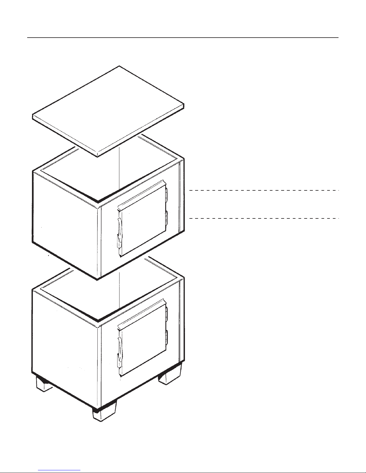
FOR THE INSTALLER
Typical Storage Bin with Extension and Bin Top
Location:
After uncrating and inspection the unit is ready for
installation. Install the machine in a location where
it has enough space around it to be accessible for
service, and reserve a minimum of 6" at the back
for air circulation on air cooled models.
Avoid hot, dirty and crowded locations. Be sure
that the location for the machine is within the
limitations described on page 3.
Storage Bin:
Tip the storage bin on its back, using parts of the
carton to protect the exterior finish. Install the legs
into the threaded holes in the bottom of the bin.
Turn the leg levelers all the way in preparation for
leveling later. Return the bin to the upright
position, remove paper covering the bin gasket.
Note: Do not push bin into position, instead lift it
there. Pushing a bin, especially one with ice in it,
can cause damage to the legs and the leg mounts.
Install the appropriate bin top on the bin, according
to the instructions for the bin top.
ice machine:
The machine is heavy, so the use of a mechanical
lift is recommended for lifting the machine high
enough to install on top of the bin. After the unit is
placed on the bin, line it up so it is even with the
back side. Secure the machine to the bin with the
hardware provided with the machine.
Remove the front panel and remove any shipping
blocks.
January 2000
Page 4

FOR THE INSTALLER: Location
ALLOW ROOM
FOR AIR
CIRCULATION
AND SERVICE
ACCESS
NME1854 & FME2404
DO NOT STACK ANYTHING IN
FRONT OF THE MACHINE
January 2000
Page 5

NME1854 & FME2404
FOR THE PLUMBER
CONFORM TO ALL APPLICABLE CODES
Water Inlet
Air Cooled Models: Connect to a water supply
that is cold and potable. Use
tubing, and connect to the single
the back of the cabinet. This connection supplies
water to both ice making systems. Install a hand
valve near the machine to control the water supply.
Water Treatment: In most areas, a water filter of
some type will be useful. In areas where the water
is highly concentrated with minerals the water
should be tested by a water treatment specialist,
and the recommendations of the specialist
regarding filtration and/or treatment should be
followed.
Water Cooled Models: A separate
line is recommended, with a separate hand valve
to control it. It is connected to a single
condenser inlet at the back of the cabinet. This
connection supplies water to both water cooled
condensers. The water pressure to all lines must
always be above 20 psig, and below 80 psig.
3
" O.D. copper
8
3
" male flare at
8
3
" O.D. copper
8
3
8
" FPT
Drains
Air Cooled Models: Connect a drain tube to the
one ¾" FPT gravity drain fitting at the back of the
cabinet (used or both ice making systems). A ¼
inch per foot fall is the minimum pitch for the drain
tubing. There MUST be a vent at the highest point
of the drain line, and the ideal drain receptacle is a
trapped and vented floor drain.
Use only ¾" rigid tubing.
Water Cooled Models: Install a separate drain
tube for the condenser discharge water. There is
one drain for both ice making systems. Connect it
to the ½" FPT condenser drain connection at the
back of the cabinet.
Storage Bin: Connect a separate gravity type
drain tube, similar to the air cooled drain. Insulation
of this drain line is recommended.
COMPLETE PLUMBING INSTALLATION,
WATER COOLED
HAND
VALVE
HAND
VALVE
AIR COOLED
MODELS
FIELD
SUPPLIED
FILTER
WATER
INLET
VENTED
DRAIN
CONDENSER
INLET
WATER
COOLED
VENTED
DRAIN
WATER
FILTER
CONDENSER
DRAIN
January 2000
Page 6

FOR THE ELECTRICIAN
CONFORM TO ALL APPLICABLE CODES
NME1854 & FME2404
Connect electrical power to the leads in the
junction box at the rear of the machine.
Check the nameplate (located on the back panel)
for the voltage requirements, and for the minimum
circuit ampacity. The machine requires a solid
chassis to earth ground wire.
The ice machine must be connected to its own
electrical circuit so that it is individually fused.
WATER
COOLED
AIR
COOLED
Voltage variation must remain within design
limitations, even under starting conditions.
All external wiring must conform to national,
state, and local electrical codes. The use of a
licensed electrician is required to perform the
electrical installation.
POWER
SUPPLY
January 2000
Page 7

NME1854 & FME2404
FOR THE INSTALLER
Final Check List
______1. Is the ice system installed indoors in a
location where the air and water
temperatures are controlled, and where
they do not exceed the design
limitations?
______2. Is there an electrical service disconnect
within sight of the installed machine?
Has the voltage been checked, and
compared to nameplate requirements?
______3. Have all the plumbing connections been
made and checked for leaks?
______4. Has the machine and bin been leveled?
______5. Is there a minimum of 6" clearance at
the back of the machine for proper
service access and air circulation?
______6. Is the water pressure a minimum of 20
psig?
______7. Has the machine been secured to the
bin?
______8. Is there clearance above the top of the
machine for service access?
______9. Is there a water shut off valve installed
near the machine?
______10. Have all of the shipping blocks been
removed?
January 2000
Page 8

START UP
NME1854 & FME2404
Pre-Start Inspection
1. Remove the front and side service panels.
2. Check that any shipping blocks have been
removed.
Start Up
The following procedure applies to each of the two separate ice making systems.
1. Go through the prestart inspection.
2. Open the hand valve, observe that water enters
the water reservoir, fills the tube from the reservoir
to the evaporator, and then shuts off. Check for
leaks.
3. Switch the master switch on.
The electrical start up sequence is automatic.
There will be a short (15 second) delay before the
gear motor and compressor start.
3. Inspect the interior of the machine for loose
screws or wires. Check that no refrigerant lines are
rubbing each other. Check that the fan blade turns
freely (air cooled).
4. Check that the unit is installed correctly according
to the final check list (page 8).
The air cooled discharge pressure will depend upon
air and water temperatures, but should be between
200 psig and 280 psig.
The water cooled discharge pressure should be
constant at about 245 psig.
The above numbers are for new, clean machines,
you can expect to see some values higher, and
some lower between different units.
6. THERE ARE NO ADJUSTMENTS TO MAKE,so
replace the panels.
4. Air cooled models will begin to discharge warm air
out the back of the cabinet. Water cooled models
will discharge warm water into the drain.
5. The unit will soon be making ice. If desired the
low side pressure of each system may be checked:
it should be 33 psig + or - 2 PSIG.
The suction line temperature at the compressor is
normally very cold, nearly to the point of frost up to
the compressor body, but not on it.
7. Clean and/or sanitize the storage bin interior,
wipe off the exterior with a clean, damp cloth.
8. Give the owner/user the service manual, instruct
him/her in the operation of the unit, and make sure
they know who to call for service.
9. Fill out the manufacturers registration and mail it
to Scotsman.
January 2000
Page 9
NME1854 & FME2404
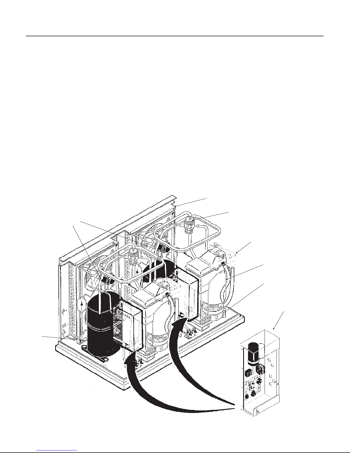
COMPONENT DESCRIPTION
Control Box: Contains the electrical controls that
operate the machine.
High Pressure Cut Out Switch: An automatic reset
switch sensing the high side refrigeration pressure.
It is set to shut the machine off if the discharge
pressure should ever exceed 450 PSIG.
Low Pressure Cut Out Switch: An automatic reset
control that shuts off the ice machine when the low
side pressure drops below a preset point, 15 PSIG.
Evaporator: A vertical stainless steel tube,
refrigerated, and water filled. In it there is a stainless
steel auger.
Compressor: The refrigerant vapor pump.
Reservoir: Float operated, it maintains the water
level in the evaporator at a constant level, it also
contains the water level sensor.
There are two of each of the above components in these machines.
Water Level Sensor: Senses if there is water in the
reservoir to make ice out of. Will shut the machine
off it there is none.
Ice Discharge Chute: Directs the ice produced by
the evaporator into the storage bin.
Ice Level Sensor: An electronic “eye”, it senses the
presence of ice in the bottom of the ice discharge
chute. Operates to turn the ice machine on and off
automatically as the level of ice in the bin changes.
Gear Motor: An oil filled, speed reduction gearbox,
driving the auger.
Drain Tube: When uncapped and lowered, drains
the evaporator.
Condenser: Air or water cooled, where the heat
removed in ice making is discharged.
Expansion valve: The refrigerant metering device.
Condenser
Hi Pressure Cut
Outs
Expansion Valve
Reservoir
Drain Tube
Gearbox
Control Box
January 2000
Page 10
 Loading...