

Page 1

TO THE OWNER OR USER:
Double System RL
The service manual you are reading is intended to
provide you, and th e m ai n tenance or s ervice
techni ci a n, with the i nf or m a ti o n ne eded to ins tall,
start up, clean, maintain and service this ice
system.
The is the freezer portion of a commercial ice
machine. It is designed to be connected to the
conden s i ng s ection of a r ef r i ge r ation sys t em ,
specifically a supermarket system.
Table of Contents
FOR THE INSTALLER: Specifications . . . . . . . . . . . . . . . . . . . . . . . . . . . Page 2
FOR THE INSTALLER . . . . . . . . . . . . . . . . . . . . . . . . . . . . . . . . . . . Page 3
FOR THE ELECTRICIAN . . . . . . . . . . . . . . . . . . . . . . . . . . . . . . . . . . Page 4
FOR THE PLUMBER . . . . . . . . . . . . . . . . . . . . . . . . . . . . . . . . . . . . Page 5
FOR THE INSTALLER: Final Check List . . . . . . . . . . . . . . . . . . . . . . . . . . Page 6
INITIAL START UP . . . . . . . . . . . . . . . . . . . . . . . . . . . . . . . . . . . . Page 7
COMPONENT IDENTIFICATION . . . . . . . . . . . . . . . . . . . . . . . . . . . . . . Page 8
COMPONENT DESCRIPTION: Control Box . . . . . . . . . . . . . . . . . . . . . . . . Page 9
COMPONENT DESCRIPTION: Evaporator . . . . . . . . . . . . . . . . . . . . . . . . . Page 10
ELECTRICAL SEQUENCE . . . . . . . . . . . . . . . . . . . . . . . . . . . . . . . . . Page 11
OPERATION . . . . . . . . . . . . . . . . . . . . . . . . . . . . . . . . . . . . . . . . Page 12
OPERATION: Refrigeration . . . . . . . . . . . . . . . . . . . . . . . . . . . . . . . . . Page 13
MAINTENANCE AND CLEANING . . . . . . . . . . . . . . . . . . . . . . . . . . . . . Page 14
MAINTENANCE . . . . . . . . . . . . . . . . . . . . . . . . . . . . . . . . . . . . . . . Page 15
CLEANING . . . . . . . . . . . . . . . . . . . . . . . . . . . . . . . . . . . . . . . . Page 16
SERVICE DIAGNOSIS: Condition - No Ice Being Produced . . . . . . . . . . . . . . . . Page 17
REMOVAL AND REPLAC EMENT . . . . . . . . . . . . . . . . . . . . . . . . . . . . . Page 18
REMOVAL AND REPLAC EMENT: Bearing And Break er . . . . . . . . . . . . . . . . . . Page 19
REMOVAL AND REPLAC EMENT . . . . . . . . . . . . . . . . . . . . . . . . . . . . . Page 20
REMOVAL AND REPLAC EMENT . . . . . . . . . . . . . . . . . . . . . . . . . . . . . Page 21
REMOVAL AND REPLAC EMENT: Evaporator . . . . . . . . . . . . . . . . . . . . . . . Page 22
REMOVAL AND REPLAC EMENT: Gearmotor . . . . . . . . . . . . . . . . . . . . . . . Page 23
CIRCUIT BOARD TESTING . . . . . . . . . . . . . . . . . . . . . . . . . . . . . . . . Page 24
Parts lists and wiring diagrams are in the center of this manual, printed on yellow paper.
This manual was printed on recycled paper, keep
it for future reference.
Note the Warning symbol where it appears. It
marks a potential hazard.
March 1997
Page 1
Page 2
Double System RL
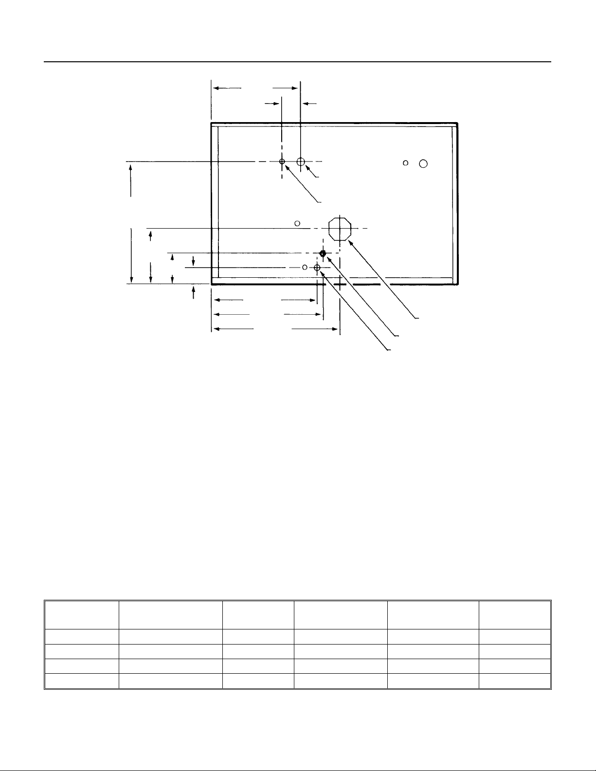
FOR THE INSTALLER: Spe cifications
BACK VIEW
20.84"
9.43"
5.25"
3"
15.53"
17.8"
18.8"
21.66"
The machine is des igned to fit the Scot sman
storage bins BH800 or B90. Leg kit KLP4 is
recommended when using both the B90 bin and
an exte nsion.
Installation Limitations:
The machine is
designed for indoor installations only. The machine
must als o be i n a co ntrolle d en v i r on m en t w he r e
the air temperatur e does not fall below 50
go above 100
The wate r tem p er a tu r e m ust be betw ee n 40
and 100
0
F.
0
F.
0
F., or
0
F.
The electrical power supp ly must not dr op below
-5% of the lowest nameplate voltage or go above
10% of the highest nameplate voltage.
3.1"
7
SUCTION LINE CONNECTION
LIQUID LINE CONNECTION
POTABLE WATER INLET 3/8" FLARE
DRAIN 3/4" FPT
"
⁄
8
1
"
⁄
2
ELECTRICAL INLET
Scotsman Ice Systems are designed and
manufactured w i th the highest regard for safety
and performanc e . Th ey m ee t or exceed th e
standards of U.L., N.S.F., and C.U.L.
Scotsman assumes no liability or responsibility of
any kind for pr o du c t s ma nu fa c t ur e d by Sc otsman
that ha ve been alt er ed in any way, including the
use of any parts and/or other components no t
specifically appr oved by Scotsman.
Scotsman reserves the right to make design
chang es and/or i mprovements at any ti me.
Specification s and designs are subject to chang e
without notice.
SPECIFICATIONS:
Model Cabinet Size System
BTUH required Voltage Ice Type
Refrigerant
FME2400RL 42"w x 27"h x 24"d R-404A 16,000 208-230 Flake
NME1850RL same R-404A 16,000 208-230 Nugget
FM2402RL same R-22 16,000 208-230 Flake
NM1852RL same R-22 16,000 208-230 Nugget
March 1997
Page 2
Page 3
FOR THE INSTALLER
Select the Location:
The unit can only be installed indoors within
the limitations described on page 2.
The ice machine will have to be connected
to the building’s R-404A refrigeration
system, check to be sure that the system
has eno ugh extra capacity to handle a
minimu m of additional 16,000 BTU’s pe r
hour @ 110
(assume a 0
Storage Bin:
Scotsman’s B90 will be the presumed bin of
choice. If using the bin extension BX87,
install heavy duty leg kit KLP4 and place
the bin into position.
Remove the paper tape from the bin edge
gasket, and install the bin extension onto
the B90.
Remove the paper tape from the bin
extension top edge, and using a
mechanical lift, install the FME2400RH onto
the top of the storage bin assembly.
Faste n th e i ce m achine to t he bi n usi n g ( 4)
5/15-18 2.5" cap screws.
Level the assembly by:
a. Turni n g th e l eg le ve l er s i n or ou t on t he
standard legs .
b. Use shims under the heavy duty legs of
the KLP4.
Locate t h e N ameplate:
locat ed on th e ba c k panel of th e mac h i ne ,
and contains the electrical characteristics
particular to the unit being installed.
Refrigeration Installation:
The skills of a refrigeration technician are
requi r ed to connect the ice mac hine to the
buildings refrigeration system.
Notes:
•
Suctio n Line and Liquid Line Stubs are
at the ba ck of the cabinet .
0
F. liquid line temperature
0
F. evaporator temperature).
The nam ep l ate is
Double System RL
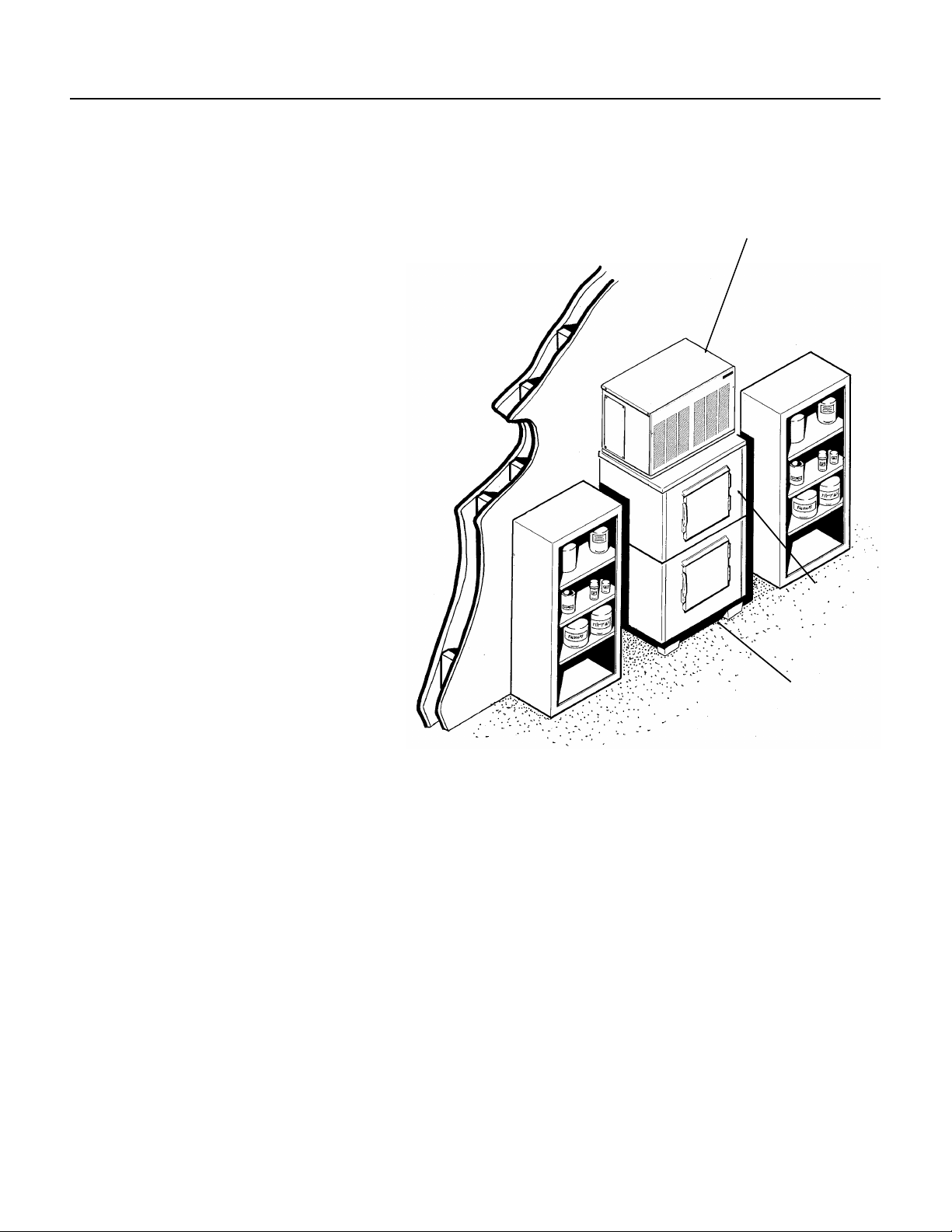
TYPICAL INSTALLATION: ALLOW ROOM FOR SERVICE ACCESS
Ice Machine
BX87 BIN
EXTENSION
B90 STORAGE BIN
•
1.5 ounc es of t he app r op r i at e r ef r i ge r an t i s in
the system as a holding charge.
•
Be sure there is enought BT U capacity.
•
Be sure the liquid connection is NOT in series
with another liquid line valve.
•
Local Codes must be observed.
•
A P-trap should be installed where there will be
more than 10’ of vertical rise in the suction line.
March 1997
Page 3
Page 4
Double System RL
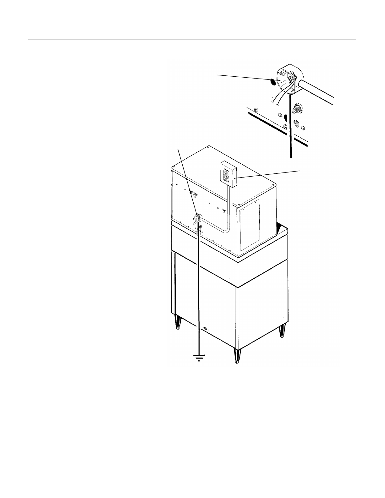
FOR THE ELECTRICIAN
CONFORM TO ALL APPLICABLE CODES
Electrical Connections:
Locate the nameplate for the current
requirements, and then determine the
wire size and type per the National
Electric Code. The machine requires a
solid chassis to earth ground wire.
Refer to the wiring diagram. The ice
machine should be connected to it’s
own electrical circuit, and be
indivi dually fused.
Voltage, when the unit is under full
load, must remain within the limitations
listed on page 2.
LOW VOLTAGE CAN CAUSE
EQUIPMENT MALFUNCTION
AND/OR DAMAGE
All external wiring should conform to
the Nati on al , State, and local el e c tr ical
codes. Usually the services of a
licensed electrician will be required.
DETAIL OF
JUNCTION BOX
JUNCTION
BOX
POWER SUPP LY
March 1997
Page 4
Page 5
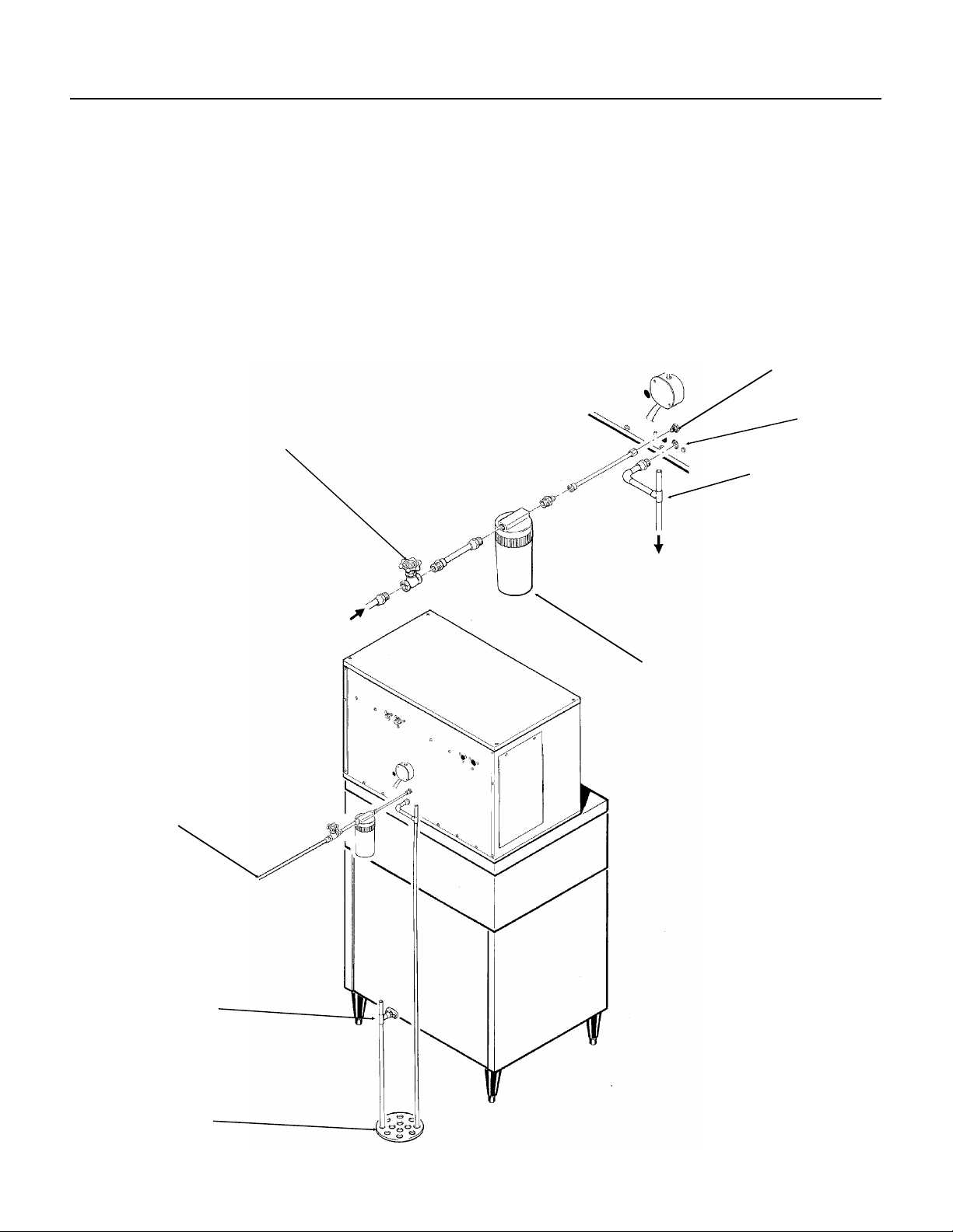
FOR THE PLUMBER
CONFORM TO ALL APPLICABLE CODES
Double System RL
Water Supply:
The recommended water supply line is 3/8" O.D.
copper tu bi n g, with a mi ni m u m operation press ur e
of 20 PSIG, and a maximum of 80 PSIG. Connect
to cold water using the male flare connection at the
back of the ma ch i ne . In stall a shut of f v alve in an
accessible spac e between the ice maker and the
water supply.
SHUT OFF
VALVE
Drain System:
All drains are of the gr avity ty pe, and must have a
minimum of 1/4" fall per foot of horizontal run. The
drains must be installed to conform to local
plumbing codes. The use of a vent at the machine
and at the bin will allow the system to drain
properly. Use on ly rigid tub ing for drains; insulation
of the bin drain is recommended.
3/8" MALE FLARE
3/4" FPT
VENT THIS DRAIN
WATER INLET
BIN DRAIN
FLOOR DRAIN
FIELD
SUPPLIED
WATER FILTE R
March 1997
Page 5
Page 6

Double System RL
FOR THE INSTALLER: Final Check List
1. Is the unit inst al led where th e ai r an d w at er
temperatures are within and will remain within the
limitations for the unit?
2. Is ther e 6" clearance at the rear of the machine
for utility connections?
3. Has the water supply line be checked for
pressures between 20 and 80?
4. Has the unit been leveled?
5. Has the shipping material been removed from
inside the cabinet?
6. Have the electrical connections been made?
7. Have the drains been installed and checked for
leaks?
8. Has the refrigeration supply been installed and
checked for leaks?
9. Has the bin and cabinet been wiped clean or
sanitized?
10. Has the warranty registration card been
properly filled out and mailed to Scotsman?
11. Has the owner been given the service manual
and been ins t r uc t ed on ho w to m ai n ta i n th e i c e
maker?
13. Has the ow ne r bee n gi ve n the name an d
telephone num ber of the local Scotsman servic e
agency?
March 1997
Page 6
Page 7

INITIAL START UP
Double System RL
1. Remove the top and front panels.
2. Open the water valve, and observe that the two
float reservoirs fill up with water and shut off.
3. Swit ch on the electrical power.
4. Open th e ha nd v al ve s ( in the liqui d l ine s ) .
5. Open th e ba l l val ves (in th e suction li ne s ) .
6. Switch on one master switch, and observe:
That liquid line valve opens
The gearmotor runs
Within a short time, that side of the machine
begins to m ak e i c e.
Water fl ow s from th e water rese r vo i r , an d the float
drops, letting in more water.
7. Switch on the other master switch, observe that:
The liquid line valve opens
The gearmotor runs
Within a short time, that side of the machine
begins to m ak e i c e.
Water fl ow s from th e water rese r vo i r , an d the float
drops, letting in more water.
8. With both sides operating, the sight glass
should remain full, and the low side pressure will
be about
2400 or 185 0 m od el s (R-404 A) 36 PSIG, + or - 2
2402 or 185 2 m od el s (R-22) 25 PSIG, + or - 2
Gearmotor amp draw should not exceed the
namepl ate rati ng .
9. Check the system very carefully for any
refrigerant leaks, repair as needed.
March 1997
Page 7
Page 8
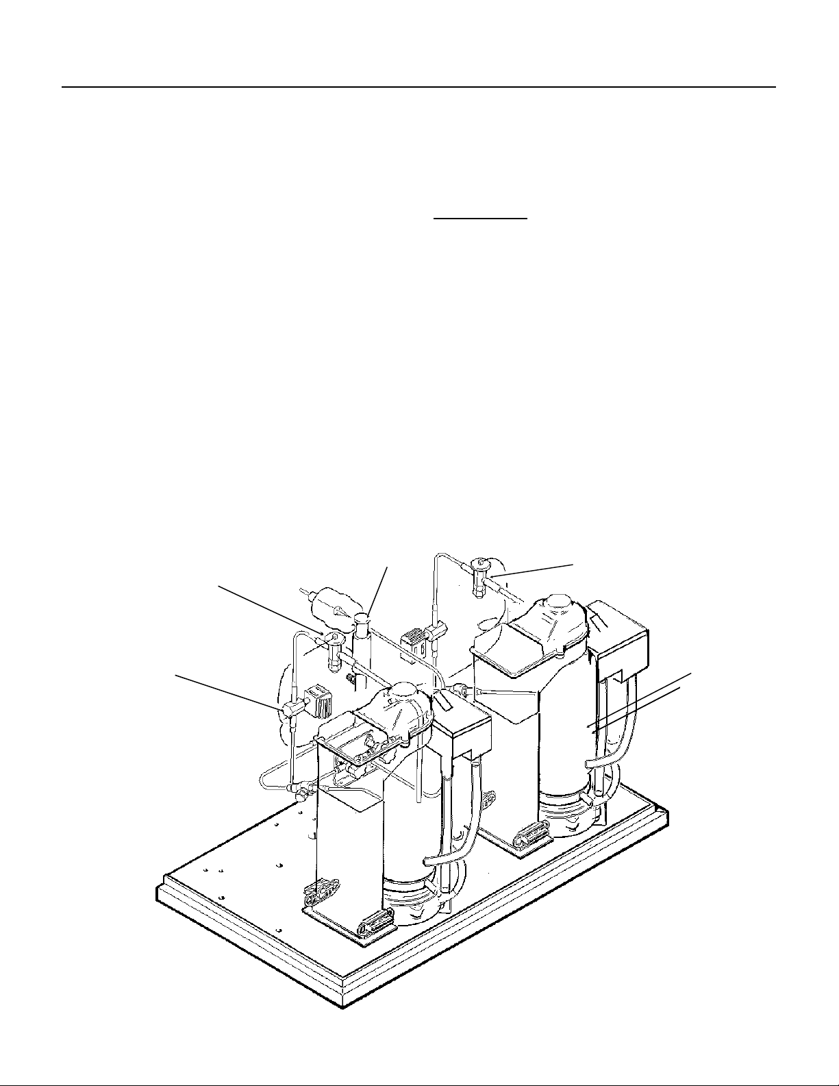
Double System RL
COMPONENT IDENTIFICATION
Liquid line valve(s)
These v alves operate to turn the ice making
process on and off.
When the i c e level drops i n th e i ce ch ut e, the ice
level sensor will cause the circuit board to close
the liquid line relay, which energizes the liquid line
valve for that side of the system. The liquid line
valve opens, and liquid refrigerant flows to the
thermos tatic expa nsion valve.
Thermostatic Expansion Valve
The metering device of each system, the valve(s)
sense the tem peratu r e of t he s uction lin e an d v a r y
the amoun t of liquid refr i g er a nt t ha t pa s se s
through the valve into the evaporator, thus
maintaining a constant level of refrigeration. TXV’s
are factory set. Do not adjust unnecessarily.
DO NOT ADJUST THE TXV UN TIL THE EPR
HAS BEEN SET.
The super h eat settin g i s 4-8
temperature of the evaporator outlet at the TXV
bulb, and check the low side pressure at the EPR
valve. Convert the pressure to temperature (using
a temperature pressure chart) and subtract the
amount from the ou tlet temperature. The resul t is
the supe r he at . U se an el ectronic thermom et er .
THERMO VALVE
0
F. Measure the
EPR VALVE
EPR: Evaporator Pressure Regulator Valve
This valve maintains a constant pre ss ure on its
inlet (evaporators) side regardless of the pressure
on the out l et (s uc t i on ) s i de . The EPR is fac tory set,
adjust only if needed. After adjusting, re-check
TXV superheat.
EPR Settings:
R-22 models (2402/1852): 25 PSIG
R-404 A m odels (2400/1850): 36 PSIG
Evaporators:
Where the water is frozen into ice crystals. As the
water cools, it begins to turn into ice, and the
slowly turning auger lifts the ice, as it is being
made, and forces it up and out of the "breaker" or
spout w he r e th e extra wat er i s com p r essed out of
the ice. The ice then drops through the chute, into
the storage bin.
THERM O
VALVE
LIQUID LIN E
VALVE
EVAPORATO R
March 1997
Page 8
Page 9

COMPONENT DESCRIPTION: Control Box
Double System RL
Circuit Board:
through sensors and relays. The sensors are: ice
level, and water level. The rel ays are for the gear
motor (with a built in time delay to clear the
evaporator of ice when the unit turns off) and for
the liquid line valve.
Transformer:
board.
On/Off Switch:
machine.
ON/OFF SWITCH
Controlling the ice machine
Supplies low voltage to the circuit
Manual co ntrol for that side of the
TRANSFORMER
CIRCUIT
BOARD
TERMINAL STRIP
March 1997
Page 9
Page 10

Double System RL
COMPONENT DESCRIPTION: Evaporator
Evaporator
water an d c o nt ai n i ng a wa te r se al and auger .
Auger:
it push es th e i ce crystals up to the top of the
evapor ator.
Water Seal :
rotat ing with the au ger, the bo tt om ha l f s t ationary ,
the sealing action being where the two seal "faces"
meet.
Ice Swee p:
with the auger to "sweep" th e ice into the ice chut e.
Divider
of the extra water is squeezed out of it before it is
discha r ge d i nt o the bin.
BEARING
: A refrigerated vertical tube filled
A solid sta inl e s s s te el do ub l e s p i r al auger,
A two part "face" seal , the top half
A plastic cap with "fingers". It revolves
: Where th e i c e is compres se d and much
Motor:
reducer.
Bearing:
the auger is thrust down, and pressure from the
auger thrust is taken up by this bearing.
A split phase motor th at drives the gear
As the ice is pushed up the evaporator,
ICE SWEEP
DIVIDER
WATER
SEAL
EVAPORATO R
AUGER
March 1997
Page 10
MOTOR
Page 11

ELECTRICAL SEQUENCE
Double System RL
Refer the wiring diagram as needed.
Each syst e m is separate
If the machine is switched off at the master switch,
but is ot he r w i se r ea dy to go, swi tching th e mas t er
switch to on does the following:
•
The bin em pty light on the circuit board goes on
•
There is a 15 sec o nd del a y
•
If there is enough water in the reservoir, the
circuit board will allow the machine to start up.
Start up consists of:
•
The liquid line relay and auger motor relay
become energized, connecting power to the
windings of the auger motor.
•
The auger m ot or starts, an d the centr i fu gal
switch closes, connecting power to the liquid
line valve coil.
•
The liquid line valve opens, and the refrigerant
flows to the ther m os t a ti c expansio n v a l ve and
into the evaporator.
•
As ice goes past the ice level sensors, the bi n
empty light will stay on, and the machine will
continue to run, unless the ice stays between
the sensors for more than 15 seconds (bin full).
At that point, the bin empty light goes out, and
the machine shuts down.
Shut Down consists of:
•
The liquid line relay opens.
•
The liquid line valve closes
•
Ice making stops
•
The auger motor is run by the circuit board for 2
more minutes, clearing out ice in the
evapor a to r , and then
•
The auger m otor rela y op en s , an d the auger
motor stops.
If the ice level sensor is clear (bin empty) for more
than 15 seconds, the machine will start up again.
Anothe r pur p ose of the cir cuit boa rd i s to tu r n th e
machine off if there is not enough water in the
machine.
•
When the water level in the reservoir falls
below the water level sensor, the machine will
"shut down"
•
When the water refills the reservoir, the
machine will start up again.
Separate from the circuit board:
•
The mast er s w it c h i s t he ma nu al co ntrol for
each system, but it is not a service disconn ect.
March 1997
Page 11
Page 12

Double System RL
OPERATION
Water
Water enters the machine through the 3/8" male
flare at the rear of the cabinet, goes to the water
reservoir which it enters thr ough the float valv e.
WATER
INLET
RESERVOIR
ICE CHUTE
The water then goes out the bottom of the
reservoir tank to the bottom of the evaporator.
Reserv oi r overflow or evaporator condensation is
routed to the drain.
WATER LEVEL
EVAPORATO R
WATER INLET
DRIP PAN DRAIN
WATER SCHEMATIC
March 1997
Page 12
Page 13

OPERATION: Refr igeration
Double System RL
The remote high side
supplies high pressure
liquid refrigerant to the
liquid line connection on
the ice machine. After
the sight glass, there are
two sepa r ate liquid l ines,
each leading to a liquid
line valve. When the
individual ice lev el
sensor causes the circuit
board t o en er g i z e the
liquid line valve, the
valve opens, allowing
the liqu id r ef r i ge r an t to
enter that expans i o n
valve. The thermostatic
expans ion valv e meters
the liquid refrigerant into
HAND VALVE
LIQUID LINE
VALVE
THERMO VALVE
LIQUID
LINE
SIGHT GLASS
the evap or a tor, wher e i t
boils off (evapo r at es)
and abso r bs heat. It
then moves through the
ball valve and into the
evaporator pressure
regulator valve, or EPR.
The EPR keeps the
evaporator pressure
above a pr e determ ined
point, ev en though th e
suction line pressure of
the remote high side
system may vary. The
refrigerant, now a low
pressure gas, moves
into the suction line of
the remote high side
system.
SUCTION LINE
EVAPORATORS
BALL VALVES
EPR VALVE
March 1997
Page 13
Page 14

Double System RL
MAINTENANCE AND CLEANING
A Scotsman Ice System represents a sizable investment of time and mon ey in any company’s business. In
order to receive the best return for that investment, it MUST receive periodic maintenance.
It is the USER’S RESPONSIBILITY to see that the unit is properly maintained. It is always preferable, and
less costly in the lo ng run, to avoid possible down time by kee ping it clean; adjusting it as ne eded; an d by
replacing worn parts before they can cause failure. The following is a list of recommended maintenance
that will help keep the machine running with a minimum of problems.
Maintenance and Cleaning should be scheduled at a minimum of twice per year.
ICEMAKING SYSTEM: In place cleaning
1. Check and clean any water treatment devices,
if any are installed.
2. Pull ou t and remove the front panel.
3. Move the ON-OFF switch to OFF.
4. Remove al l the ice from the storage bin.
5. Remove the cover to the water reservoir and
block the float up.
6. Drain the water reservoir and freezer assembly
using the drain tube attached to the freeze r water
inlet. Return the drain tube to its normal upright
position and replace the end cap.
7. Prepare the cleaning solution: Mix eight
ounces of Scotsm a n Ice Machi ne Cle aner with
three quarts of hot water. The water should be
between 90-115 degrees F.
Scotsman Ice Machine
Cleaner contains acids.
These compounds may
cause burns.
If swallowed, DO NOT
induce vomiting. Give
large amounts of water or
milk. Call Physician
immediately. In ca se of
external contact, flush with
water.
Keep out of the reach of
children.
8. Slowly po ur th e cl ea ni n g solution in to the wa te r
reservoir until it is full. Wait 15 minutes, then
switch the master switch to ON.
9. As the ice m aker begins to use wat er from the
reservoir, continue to add more cleaning solution
to maintain a full reservoir.
10. After all of the cleaning s olution has been
added to the reservoir, and the reservoir is nearly
empty , sw i tch the mast er sw itch to OFF.
11. After draining the reservoir, as in step 6, wash
and rinse the wat er r es e r voir.
March 1997
12. Go thru steps 13-19 to sanit ize th e ice machin e
water system.
13. Mix two gallons of sanitizer soluti on. Use an
approved sanitizer.
A possib l e sanitiz er so l ut i on ma y be ob ta i ne d by
mixing tw o gallons of warm (90-115
o
F.) pota ble
water with 1 ounce of household bleach.
14. Slowly pout the sanitizer solution into the water
reservoir until the float rises, then switch the
master switch ON.
15. As th e ice machine uses water from the
reservoir, continue to pour the sanitizer solution
into the reservoir.
16. Afte r
1
of the sani t i zer s o l ut i on has be en
⁄
2
added to the reservoir, and the reservoir is nearly
empty , s wi tch the master switch OFF.
17. Drain the reservoir and thoroughly wash the
interior of the reservoir and cover with sanitizer
solution. Be sure the drain hose is upright and
capped.
18. Remove the block from the float in the water
reservoir.
19. Switch the master switch to ON
20. Continue ice making for at least 15 minute s, to
flush ou t any cleani ng solu tion.
DO NOT USE any ice produced from the
cleaning solution. Be sure no ice remains in
the bin.
21. Remove all ice from the storage bin.
22. Add war m w at er to the ice storag e bi n and
thoroug hl y wash and r i ns e al l sur faces wi th i n th e
bin.
23. Sanitize the bin interior by washing the interior
of the bi n w it h the balanc e of the sanitizer sol ution.
24. Switch the master switch ON.
Page 14
Page 15

MAINTENANCE
Electrical Shock Hazard
Electrical shock can cause
personal injury.
Disconnect electrical
power before beginning.
1. The bin control uses devices that sense light,
therefore they must be kept clean enough so that
they can "see". At least twice a year, remove the
bin control sensors from the base of the i ce chute,
and wipe the inside clean, as illustrated.
2. The ice machin e s e nses water l evel by a pro be
located in the water reservoir. At least twice a
year, the probe should be removed from the
reservoir, and the tip wiped clean of mineral
build-up.
Double System RL
SLIDE ICE
LEVEL
CONTROLS OUT
OF CHUTE
CLEAN THE ICE
LEVEL CONTROL
SENSORS
RESERVOIR
CLEAN THE
WATER LEVEL
SENSOR
/////////////////////////////
CAUTION: THE
TIMP IS MADE OF
GLASS
///////////////////////////////
3. The bearing in the breaker should also be
checked at least
Check the bearing by:
•
pushing the bail clamp back and removing the
ice chute c over
two times p er year
.
Inspe ct the ass embly, looking for wear.
See Remo v a l and Re pl a c em e nt t o r ep l ace bearing
or seals. Reverse to reassemble.
4. Check and tighten all bolts and screws.
ICE SWEEP
BREAKER
COVER
•
unscrewing the ice swee p
•
unscrewing the breaker cover
•
unscrewing the auger stud
March 1997
Page 15
Page 16

Double System RL
CLEANING
In some installations the water supply to the ice
maker will be so concentrated with dissolved
minerals, (such as calcium carbonate) that as ice
is mad e, the evaporator and au ge r become
coated with the minerals, requiring a more frequent
cleaning than twice per year. If in doubt about the
condition of the evaporator and au ger, the auger
can be removed so the parts can be inspected.
Note: Water filters can filter out suspended solids,
but not dissolv ed sol i ds . "S of t" w at er m ay no t be
the complete answ er . Check with a w ater
treatm en t s p eci a l i st re ga r di n g w at er treatment.
ALLEN HEAD
DIVIDER, AUGER
AND SLOTTED
COLLAR
SCREWS
Switch off electrical power, and shut off the
water supply.
For more information on removal of these
parts, see REMOVAL AND REPLACEMENT.
1. To remove the auger, remove front and top
panel. If top panel ca nnot be removed, or i f th er e is
less tha n 6" c learance over th e top of the ma chine,
the gearmotor/evaporator may be slid out for
service access. See Removal And Replacement.
2. Push bail clamp back and remove ice chute
cover.
3. Unscrew and remove ice sweep.
4. Loosen band cla m p un der ice chu t e , and
remove i ce chute from evaporator.
5. Remove 4 allen he ad screws ho l di n g br e aker to
evapor a to r .
6. Pull up on breake r to r emove au ger.
Allow the auger to dr y, the sta inless steel of the
auger and evaporator
Clean the auger and evaporator as required. DO
NOT HONE THE EVAPORATOR.
7. Replac e th e w at er s ea l.
8. Reverse to reassemble.
be clea n an d br i g ht.
must
March 1997
Page 16
Page 17

Double System RL
SERVICE DIAGNOSIS: Condition - No Ice Being Produced
STATUS:
Check:
A.
Check: The
B.
. Check the
C
reservoir. Restore/adjust water level.
STATUS:
. Check: The gear
D
Check: The
shoul d be OF F
1. If the
side should have between 208-230 volts. If the line side has the correct voltage and the
2. If the tr ansform er is good, and the
INFORMATION
3. If the tr a nsf or m e r is fi ne , an d the "no water " l i gh t i s ON , check the
NOTHING OPERATES
Voltage
to the uni t, restore it if there is none. Compare to the nameplate.
mast er sw it ch
wate r level
, switch ON i f of f.
in the reservoir. The machine will not run if there is not enough water in the
NOTHING OPERATES
motor
indicator lights
.
bin empty
a. Transformer "load" side should have 12 to 15 volts. If not, check the "l ine" sid e. The line
load side does not, replace the tran sformer.
a. Remove sensors by sliding them sideways out of the ice chute. Visually inspect them,
clean if ne ed ed.
b. Look through the ice chute "eye" hole for somet hing block ing the ice chute.
c. If the unit still does not run, replace the ice level sensors.
d. If the bin empty light is still OFF, check the
a. Check the water level in the
b. Remove the water level sensor from the reservoir and clean the tip if dirty.
CAUTION: THE TIP IS MADE OF GLASS
c. Replace the water level sensor. If the no water light is still on, check that the
"water sen" plug is firmly plugged into the circuit board.
d. If the no water light is still on, SEE LAST PAGE FOR TESTER INFORMATION
e. If after the above, the machine still will not run, replace the water level sensor
, if it will not run, the liquid line valve will not open. If no power to it:
and
on the circuit board, the
no water
lights are off, check the
bin empty
reservoir,
bin empty
light is OFF, check the
circuit board
restore if low. If the water level is ok:
light sh ould be ON, the
transformer
.
ice level sensors
. SEE LAST PAGE FOR TESTER
water level sensor.
no water
.
light
STATUS:
Check the
A.
The relay is on th e circuit board, if it does not supply power to the liquid line valve, the
valve will not open.
1. Check for power at the valve coil, if none:
2. Check the valve coil. If the coil is open, replace the liquid line valve.
3. Check th e auger dri ve motor centrifugal switch. If, when the drive motor is running,
contac t 4 (b l ac k wi r e re m oved) has no pow er, and al l of the abov e sw i tches ha ve been
checked, replace the centrifugal switch, or the drive motor.
4. If the liquid line valve relay on the circuit board has power on the NO contact, but not on the COM
contac t , r ep l ace the cir cuit board .
GEARMOTOR OPERATES, BUT NO ICE IS MADE
liquid li n e va lv e re la y.
Check for po w er at t he liq ui d li n e val ve relay at th e ci r c u i t bo ar d .
a.
If there is power at the relay, but none at the liquid line valve coil,
Check for an open wire between the relay and the valve.
March 1997
Page 17
Page 18

Double System RL
REMOVAL AND REPLACEMENT
WATER RESERVOIR
1. Shut of f th e w at er su pply to the ic e ma ker .
2. Remove front panel and reservoir cover.
3. To remove
tube, push in the tab behind the reservoir and pull
valve assembly out of the reservoir tank.
4. To remove reservoir, disconnect water inlet
compression fitting at reservoir inlet.
5. Remove drain hose from reservoir.
6. Remove evapor ator inle t ho se from res e r vo i r .
7. Remove mounting screws from reservoir
bracket, and remove reservoir from ice maker.
8. Reverse to reassemble.
Internal
Plunger
float only, disconnect water inlet
BIN CONTROLS (Ice Level Sensors)
1. Disconnect electrical power.
2. Remove front panel.
3. Remove control box cover.
4. Locat e i c e ch ute, at the base of the c hu te , in
front of an d behind it ar e two plas t i c bi n co ntrol
mounts.
5. Slide each bin control to the left, and in the
contr ol bo x , di sconne ct the electrica l le ad s
connecting the bi n co ntrol to the circui t boa r d.
6. Reverse to reassemble, be certain that the bin
contro ls are aligned so that the ice lev el sensors
are visible (centered) through the holes in the cube
chute.
SLIDE BIN
CONTROLS
IN AND OUT
Float Valve
March 1997
Page 18
Page 19

Double System RL
REMOVAL AND REPLACEMENT: Bearing And Breaker
Note: Removal of the auger, water seal,
evapo r ator and ge armotor mu st begin a t the top of
the assem b l y .
To Remove the Breaker Bearing Assembly:
Electrical Shock Hazard
Electrical shock can cause
personal injury.
Disconnect electrical
power before beginning.
1. Remove panels and disconnect electrical power.
2. Push ba c k bail clam p, re m ove insulation
retaining strap and insulation, remove ice chute
cover.
3. Unscrew and remove ice sweep.
4. Loosen band cla m p un der ice chu t e , l i ft up and
remove ice chute.
5. The bre aker may be re moved from th e au ger
and evaporator without disturbing the auger.
a. Unscrew breaker cover from breaker (left hand
threads)
b. Unscrew auger stud from top of auger.
c. Unsc rew 4 al l e n he ad ca p sc r e w s ho l di n g
breake r to evaporator.
Step 5- a Step 5-b Step 5-c and Step 6
d
. Lift up , an d r em o ve br eaker/be ar i n g assembl y
from auger & evaporator.
6. Service the bearing. Check for rust, rough spots
and damage.
a. The bear ing is pressed into the breaker, to
remove the bearing and rep l ace it an arbor press
is need ed .
b. Replace lower seals before installing new
bearin g i n br e aker.
Note: seals must be pressed in with a tool pushing
against the outer edge only, they will not install by
hand.
Replac e parts as required. R e- g r ea s e be ar ing with
Scotsman part no. 19-0609-01 bearing grease.
Replac e top seal, an d check the o- r ings, repl ac e i f
cut or torn.
7. Reverse to reassemble: specific tools and
materi a l s ar e re qu i r ed t o ins t al l pr o perly.
a. Add food grade gr ease such as Scotsm an part
number 19-0569-01 to the seal area before
installing on the auger.
b. Check the seal to shaft areas for cuts, or rough
spots: none are permitted.
ICE SWEEP
BREAKER
COVER
BEARING
SEALS
SLOTTED
COLLAR
AUGER
STUD
DIVIDER
March 1997
Page 19
Page 20

Double System RL
REMOVAL AND REPLACEMENT
To Remove the Auger:
Turn off the water to the machine, and uncli p the
evapor ator drain hose, pull i t down and drain the
evaporator into the bin or a container.
Electrical Shock Hazard
Electrical shock can cause
personal injury.
Disconnect electrical
power before beginning.
1. The top panel must be removed.
2. Remove ice ch ut e c over.
3. Unscrew ice sweep.
4. Loosen band clamp and remov e i ce chute body.
5. The auger and bre aker/bearing may no w be
removed as an asse m bl y .
a. Unscrew 4 allen head cap screws holding
breake r to evaporator.
b. Lift up on br e aker and r em o v e au ge r fr om
evapor a t o r .
d. Lift up and re m ove breaker from evapora t o r .
e. If the auger is stuck use a slide hammer type
pulle r to pull on th e auger at the threaded hole.
The siz e of t ha t ho l e i s 5/ 8" - 18 .
Inspect the auger, the crit ical areas of the auger
are:
1. The auger body. It should be clean and
shining. Sometimes an auger will appear clean
when wet, but after it is dry it will be seen to be
stained. Scrub the auger with ice machine cleaner
and hot water.
Ice machine cleaner is an acid. Handle it with
extreme care, keep out of the reach of children.
2. The water seal area. Because the auger has
been removed, the water seal will have to be
replaced. Remo ve the wat e r seal top half from the
auger, and inspe ct the auger for m inerals cle an as
required.
DIVIDER
AND
AUGER
ASSEMBLY
Note: If the auger is stuck, the breaker must be
removed from the auger.
The bre a ker may be re moved from the auger and
evaporator without disturbing the auger.
a. Use spanner wrench and unscrew breaker
cover fr om breaker (l eft hand thr eads)
b. Unscrew auger stud from top of auger.
c. Unsc rew 4 al l e n he ad ca p sc r e w s ho l di n g
breake r to evaporator.
SLIDE HAMMER
PULLER
THREAD INTO THE
AUGER HERE
March 1997
Page 20
Page 21

REMOVAL AND REPLACEMENT
Moving Parts Hazard.
Moving parts can cause
personal injury.
Disconnect electrical
power before beginning.
To Remove the Water Seal:
(Assum i n g al l s t ep s to r em o v e the auger ha ve
been performed.)
1. The gearmotor/evaporator assembly will have to
be exposed.
2. Remove the 4 hex hea d c a p sc r e w s hol d i ng the
evapor a to r t o th e ge ar m o to r ass e m bl y. Lift the
evapor a to r up an d off of the gearmotor .
3. Remove the snap ring or wire retainer from the
grove under the water seal.
4. Pull or dr ive out the l ow e r hal f of th e w ater seal.
Double System RL
To Replace the Water Seal:
1. Lubricate the water seal with water, and push
the water s e al into the bott om of the evapor a t o r
slightly past the grove for the snap ring.
2. Replace the snap ring and pull the water seal
down agai n s t it.
3. The part of the water seal that rotates with the
auger mu s t al so be re pl a c e d. Rem o ve the old part
from the auger and clean the mounting area.
4. Place a small bead of food grade silastic sealant
(such as 732 RTV or Scotsman part number
19-0529-01) on the area of the auger where the
water seal is to be mounted.
5. Carefully push the water seal (rubber side
agains t the auger shoulder and th e si l a st ic.)
CAUTION
Do not get an y s i lastic onto the face of the seal .
6. Allow the auger and seal to air dry until the
silastic is dry on the surface.
7. If the original water seal was leaking, it would be
a good idea to inspect the interior of the gearmotor.
WATER
SEAL
RETAINING
RING
PLACE FOOD
GRADE SEALANT
HERE
March 1997
Page 21
Page 22

Double System RL
REMOVAL AND REPLACEMENT: Evaporator
To Replace the Evaporator:
(Assum i n g al l th e steps for r em o val of the th r ust
bearin g, breaker, auge r , an d w ater seal have been
performed.)
1. Shut th e ha nd valves in th e l i qu i d an d s uc t ion
lines to the evaporator being serviced; then
discharge the refrigerant.
2. Unsweat the refrigerant connections:
a) At the thermostatic expansion valv e outlet.
CAUTION
Heat sink the TXV body when unsweating or
resweating the adjacent tubing.
b) At the suction line at the joint about 3" from the
evaporator.
3. Remove the
evaporator.
4. Unsweat the drier
from the l iquid line.
5. After installing a
new water seal in the
new eva po r ator (see
"To Rep lac e t he
Water Seal") sweat in
the new evaporator at
the old co nn ections.
6. Install an new drier
in the liquid line.
7. Evacuate the
system until
dehydrated, then
weigh in the
namepl ate charge.
Check for leaks.
8. Instal l auger,
breake r , br eaker
bearin g assemb ly ,
and ice di sc h ar g e
chute i n r ev e r se order
of disassembly. See
"To Reassemble
Evapor ator and Auger"
ICE SWEEP
BEARING
To Reassemble the Evaporator and Auger
1. After the gearmotor has been inspected, fasten
the evap or a tor to the ge ar m ot or , tor que the bolts
to 110 inc h pounds.
2. Lower the auger into the evaporator barrel,
slightly turning it to match up with the drive end.
Do Not Drop Into the Evaporator.
3. Complete the reassembly by reversing the
disassembly for the breaker & thrust bearing
assembly.
AUGER
EVAPORATOR
DRIP PAN
March 1997
Page 22
DIVIDER/BREAKER
Page 23

REMOVAL AND REPLACEMENT: Gearmotor
Double System RL
To Remove and Repair the Gearmotor
Assembly:
(Assuming that the procedures through removal of
the water seal have been performed.)
1. Remove the el ectr ical wires from the gear dr ive
motor.
2. Unscrew the 4 cap screws holding the
gearmotor to the gearmotor plate.
3. Remove the gearmotor from the ice maker.
To Inspect the gearmotor.
A) Remove the cap screws holding the gearmotor
case halves together and pr y the two cases apar t.
B) To lift off the cover, lift up until you can feel
internal contact, then pull the cover towards the
output gear end, and then
lift the cover (with drive
motor attached) up and
away from the gear motor
case.
Note: The case cover
output gear, bearings, and
shaft are one pressed
together assembly.
Replace as a unit.
C) Inspect the oil, gears,
and bearings. If the oil
level and condition is
acceptable, quickly check
the gears and bearings.
They are likely to be fine if
the oil is.
If there is evidence of
water in the oil (rusty
bearings and gears; the oil
having a creamy white
appearance; oil level too
high) carefully inspect the
bearings and gears. If in
doubt about the condition
of a part, replace it. The oil
quantity is 14 fluid ounces,
do not overfill.
Note: The gears and
bearings are available only
as pressed together sets.
GEARCASE
D) After replacing parts as required, (if any)
reassemble the gearcase. The two smaller gears
and the oil should be in the lower case, the output
gear will be with the cover. As you lower the cover
onto the lower case, cover will have to be moved
closer to the second gear after the output gear has
cleared the second gear top bearing.
E) After the case is together, and the locati ng pins
are secure in both ends, replace all cap screws.
4. Bench test the gearmotor, check for oil leaks,
noise , an d am p draw.
SEAL
MOTOR
BEARING
GASKET
March 1997
Page 23
Page 24

Double System RL
CIRCUIT BOARD TESTING
These procedures require the machi ne to be connected to the power supply . The voltages of the
elect ronic circ uit are ver y lo w, but HIGHER VO LT A GES ARE PRES EN T IN T HE U N IT. Do not touc h
anythi n g bu t the tester wh i le the unit is be i ng checked out . M ak e al l connecti on s to th e c ir c u i t bo ar d with
the ELECTRICAL POWER OFF.
INSTRUCTIONS FOR USING TESTER,
(These instructions assume that the unit
(Optiona l , or d er pa r t no . A3 39 42 - 001)
will not run,
and prior investigation of electric power, controls,
and mechanical parts indicates that the electronic circuit may be at fault.)
Note: All testing is done with the electrical power
on, the master switch on.
1. Unplug “photo trans” and “LED” connectors from
the circuit board .
2. Plug “photo trans” and “LED” connectors from
the test er i nt o th e ci r cuit board .
3. Unplug "water sen" connector from the circuit
board.
4. Plug "water sen" connec tor from Scotsman
tester into the circ u i t bo ar d .
Bin Control:
a. Move the “bin full” switch on the tester to Full.
The light on the tes ter should be ON.
If the li ght on the tester is no t on, the circuit board
shoul d be re pl a c ed .
b. If the light on the tester IS on, move the “bin
full” switch to Bin Empty. The light on the tester
should go OFF, and the Bin Empty light on the
circuit board shou ld go ON.
If the Bin Empty light is ON, wait 10-20 seconds for
the machine to start, if the machine starts, replace
the ice level sensors.
If the Bin Empty light does not come ON, the
circuit board shou ld be replaced.
Water Level
a. Move “water” switch on tester to No Water
position. The No Water light on the circuit board
should go ON. If not, replace the circuit board.
b. Move the “water” switch on the tester to the
Water position. The No Water light on the board
shoul d go OF F. I f no t r ep l ace t he ci r cui t board. If
the ligh t do es go off, repl a c e th e w at er l evel senso r .
If the Bin Empty light is ON, wait 10-20 seconds for
the mac hine to start. The machine shou l d start.
LIGHT GOES ON
LED
SWITCH TO
"FULL"
PHOTO TRANS
WATER SENS
LIGHT GOES
ON
SWITCH TO
"NO WATER"
March 1997
Page 24
 Loading...