

Page 1

FM1202 SERVICE PARTS
This parts list contains the service parts and
wiring diagrams for this model. Check the model
number in question to be sure that it is applicable
to this parts list.
TABLE OF CONTENTS
Cabinet...............................................................................2
Air Cooled Refrigeration.....................................................3
Water Cooled Refrigeration................................................4
Water System.....................................................................5
Gearmotor...........................................................................6
Evaporator..........................................................................7
Control Box.........................................................................8
Wiring Diagrams.................................................................9
Page 2
FM1202 SERVICE PARTS
August 1993
Page 1
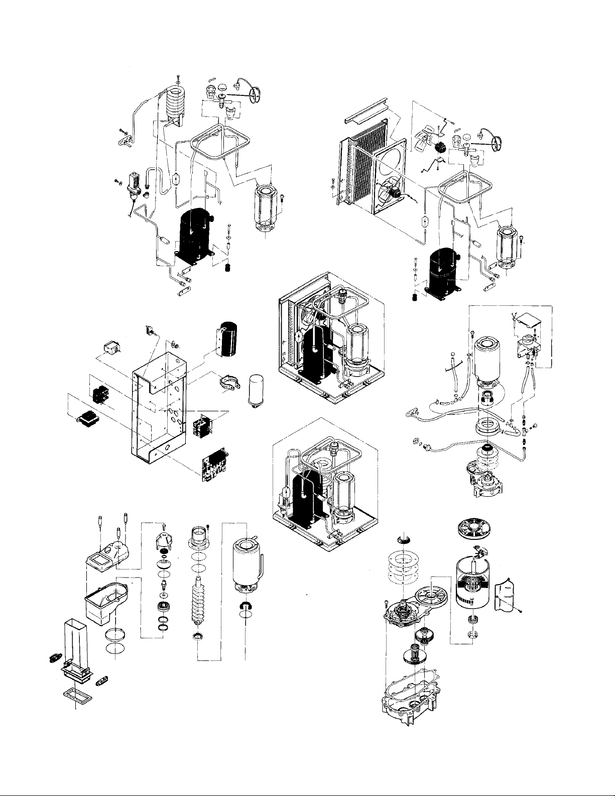
Page 3
AIR
COOLED
Water Cooled
15
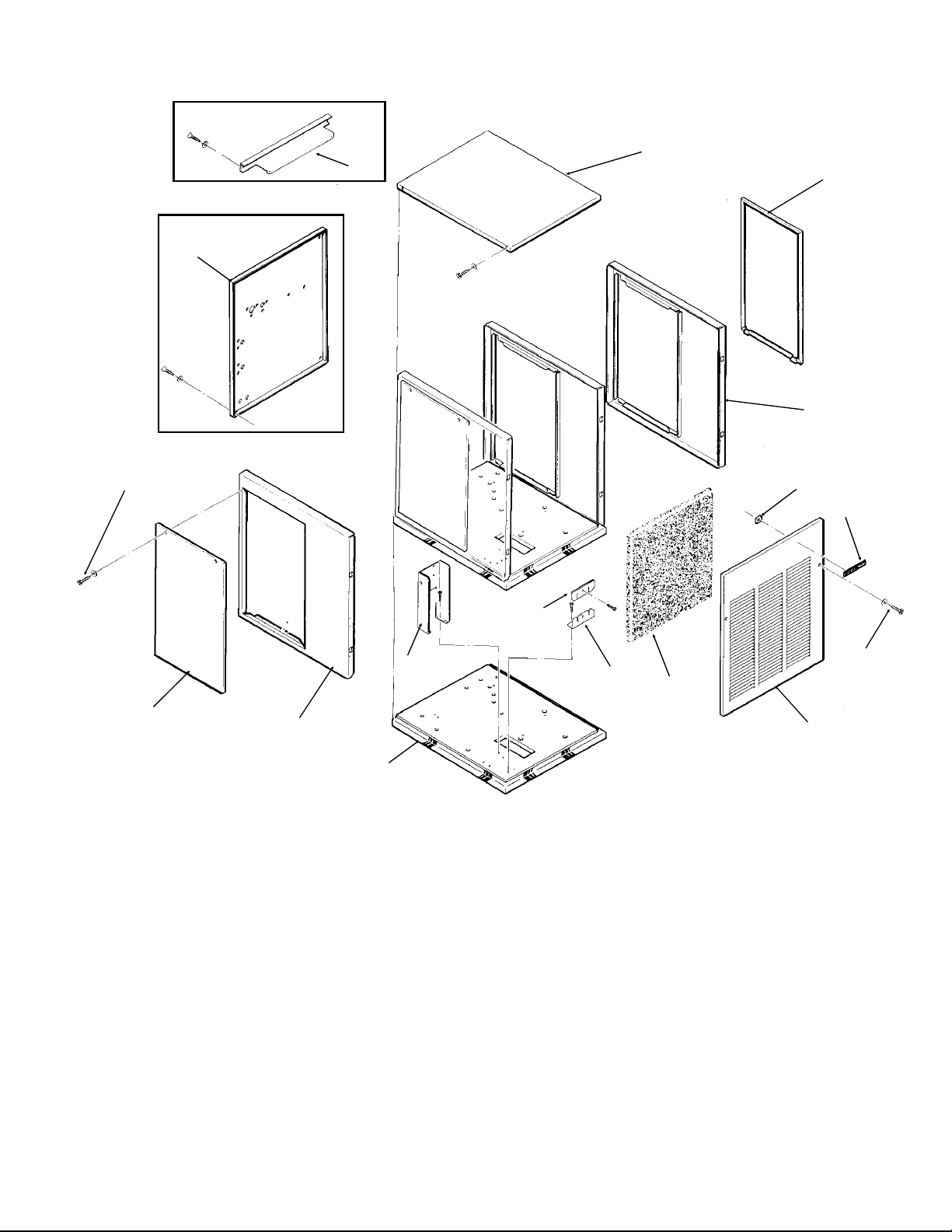
FM1202 SERVICE PARTS
Cabinet Assembly
1
2
3
4
14
12
3
13
16
ITEM PART
NUMBER NUMBER DESCRIPTION
1 A33233-001 Condenser Support
2 A33256-001 Top Panel, Painted
A33256-002 Top Panel, S.S.
3 A34038-001 Service Panel, Painted
A34038-002 Service Panel, S.S.
4 A33292-001 Right Side Panel, Painted
A33292-002 Right Side Panel, S.S.
5 03-0271-00 Speed Clip
6 15-0711-01 Emblem
7 03-1419-08 Screw
8 A33255-001 Front Panel, Painted
A33255-002 Front Panel, S.S.
5
6
11
7
10
9
8
ITEM PART
NUMBER NUMBER DESCRIPTION
9 02-2976-01 Filter Assembly
10 03-1660-01 Filter clip
11 A34348-001 Ft. brace
12 A34039-001 Control Box Support
13 A32435-001 Left Side Panel, Painted
A32435-002 Left Side Panel, S.S.
14 03-1404-12 Screw
15 A33252-001 Rear Panel,
Water Cooled
Painted Only
16. A34042-001 Base
November 2004
Page 2
Page 4
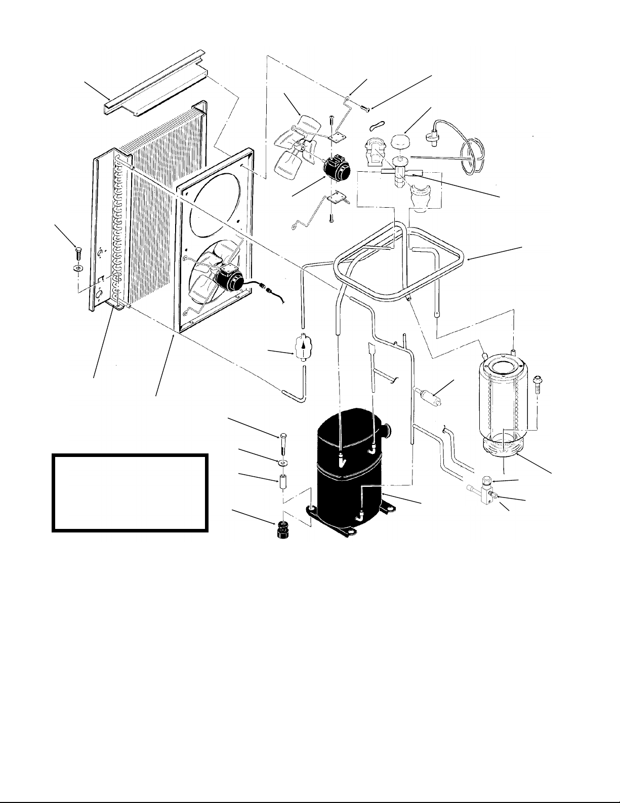
FM1202 SERVICE PARTS
Air Cooled Refrigeration
11
19
16
3
1
2
4
5
6
7
18
17
15
14
NOTE: 60 cyele replacement
compressors include a
crankcase heater which was
not part of the original design.
The crankcase heater may be
used or disconnected.
13
12
ITEM PART
NUMBER NUMBER DESCRIPTION
1 18-3815-01 Fan Blade
2 12-1576-02 Fan Motor
3 02-2378-01 Fan Bracket
4 03-1531-01 Screw
5 A32961-020 Insulation Kit (3 piece)
6 11-0477-20 Thermo Expansion Valve
7 A35566-001 Suction Line
8 A32890-020 Evaporator
9 16-0832-20 Access valve
9a 16-0832-02 Stem cap
9b 16-0832-03 Core cap
10 11-0446-27 Hi Pressure Cut Out
11 03-1645-01 Screw
10
9a
20
9
8
9b
ITEM PART
NUMBER NUMBER DESCRIPTION
12 18-6800-01 Grommet
13 18-2300-27 Sleeve
14 03-1407-07 Washer
15 03-1405-20 Cap Screw
16 02-3319-02 Dryer
17 A33231-001 Fan Shroud
18 18-8717-01 Condenser
19 A33233-001 Condenser Mount
20 18-8716-23 Compressor 208-230/60/1
18-8716-25 Compressor 200-230/60/3
18-8716-26 Compressor 220-240/50/1
(18-8716-06 for 50 cycle only)
all compressors have internal overloads
18-8716-23, 18-8716-25 have crankcase heaters
November 2004
Page 3
Page 5

FM1202 SERVICE PARTS
Water Cooled Refrigeration
17
16
15
11
1
14
2
3
4
5
19
7
13
NOTE: Replacement
Compressors include a
crankcase heater which was
not part of the original design.
The crankcase heater may be
used or disconnected.
ITEM PART
NUMBER NUMBER DESCRIPTION
1 18-8718-25 Condenser
2 03-1645-01 Screw
3 11-0477-20 Thermo Expansion Valve
4 A32961-020 Insulation Kit (3 piece)
5 A35566-001 Suction Line
6 A32890-020 Evaporator
7 03-1405-20 Cap Screw
8 03-1407-07 Washer
9 18-2300-26 Sleeve
10 18-6800-01 Grommmet
11 03-1645-01 Screw
8
9
10
12a
12
12b
18
12 16-0832-20 Access Valve Complete
6
12a 16-0832-02 Stem cap
12b 16-0832-03 Core cap
13 11-0446-27 Hi Pressure Cut Out
14 16-0401-02 Elbow
15 11-0424-01 Water Reg. Valve
16 03-1403-14 Screw
17 A34044-001 Drain Assembly
18 18-8716-23 Compressor 208-230/60/1
18-8716-25 Compressor 200-230/60/3
18-8716-26 Compressor 220-240/50/1
(all have internal overloads & 18-8716-23,
18-8716-25 have crankcase heaters)
19 02-3319-02 Dryer
November 2004
Page 4
Page 6

FM1202 SERVICE PARTS
Water System
18
21
22
25
20
20
23
24
2
1
27
7
3
17
12
5
11
4
6
8
26
14
19
16
15
13
ITEM PART
NUMBER NUMBER DESCRIPTION
1 03-1405-41 Cap Screw
2 A33101-022 Water Level Sensor
3 A32890-020 Evaporator
4 02-2936-01 Res. Cover
5 A32907-001 Float Assembly with pin
housing seal, rubber seat, insert & float
02-3190-01 Rubber seat
6 A32929-020 Reservoir Assy Complete
7 A32777-001 Retaining Ring for seal
8 16-0791-01 Half Union
9 16-0162-00 Strainer
10 13-0079-03 Tube, 3.2" req.
11 16-0670-02 Tee
12 02-0929-23 Water Seal
13 13-0868-01 Water Shed
9
10
8
ITEM PART
NUMBER NUMBER DESCRIPTION
14 A32050-001 Drip Pan
15 A27318-001 Water Inlet Fitting
16 03-1394-01 Pal Nut
17 13-0079-03 Res. Overflow, 8" req.
18 A34045-001 Drain Casting, air cooled
19 13-0704-00 Gasket
20 02-2814-08 Clamps
21 13-0674-06 Evap. Drain, 14" req.
22 13-0840-01 Plug
23 13-0674-06 Evap. Inlet Tube, 5" req.
24 16-0670-01 Tee
25 A33203-001 Tube, Preformed
26 13-0079-03 Drain Tube, 24" req.
27. 03-1417-13 Lockwasher
November 2004
Page 5
Page 7

FM1202 SERVICE PARTS
Gearmotor
1
3
2
10
*NOTE: GEARCASE
COVER INCLUDES
COVER, OUTPUT
SHAFT, KEY, OUTPUT
GEAR, BEARINGS
AND SEAL
4
11
12
5
6
7
13
14
ITEM PART
NUMBER NUMBER DESCRIPTION
1 13-0868-01 Water Shed
2 A32379-029 Seal
3 no number End bell
4 A32379-026 Bolt (6 / pack)
8
5 A32379-022 Gearcase Cover*
6 A32379-024 1st Gear and Bearings
7 A32379-023 2nd Gear and Bearings
8 A32379-021 Gasket
9 A32379-020 Gearcase
10 12-2430-24 Start switch, Emerson
12-2430-44 Start switch, GE split phase
9
11 12-2430-22 Drive Motor 208 - 230 volt
12 12-2430-29 Rotor Bearing, Emerson
12-2430-49 Rotor bearing, GE split phase
13 A32379-028 Seal, not used on replacement
gear reducers or covers after 2/2000
14 A32379-027 Oil, 1 Container
15 A33220-022 Complete Assembly 208-230 volt
A33220-030 Gears, oil & cases. No motor.
November 2004
Page 6
Page 8

FM1202 SERVICE PARTS
1
2
Evaporator
3
Not Illustrated:
Bail Clamp, pn
A34969-001
4
5
6
7
8
9
ITEM PART
NUMBER NUMBER DESCRIPTION
1. 02-2933-01 Hex Stud
2. A32891-021 Switch Assembly
13-0617-53 O-ring
12-2398-01 Manual reset swtich
3. 02-2930-01 Ice Chute Cover
4. A32963-001 Insulation Top (half)
5. 02-2926-01 Ice Chute Body
6. A33102-001 Insulation Collar Inside
A35419-020 Strap kit
7. 02-2929-01 Ice Chute Lower
8. A37708-021 Ice level sensors (set of 2)
9. A32930-001 Chute Gasket
10. 03-1405-52 Hex Cap Screw
11. 02-3001-01 Ice Sweep
12. 13-0871-01 Water Shed
13. 02-2978-01 Lip Seal
14. 02-3128-20 Breaker Cover
15. 13-0617-54 O-Ring
16. 08-0660-01 Auger Stud, includes item 17
17. no number Thrust Washer, part of #16
18. A34559-020 Bearing
19. 02-2977-01 Lip Seal
18
8
24
16
22
11
33
19
10
26
4
12
13
17
15
20
14
21
25
23
27
28
29
29
30
31
32
20. 03-1405-27 Screw
21. 13-0617-52 O-Ring
22. 02-2916-01 Slotted Collar
23. 13-0617-45 O-Ring
24. 03-1544-08 Soc. Head Screw
25. A34505-020 Breaker (Divider)
(includes 18 & 19)
26. A38071-022 Auger
27. A32890-020 Evaporator
28. 03-1405-41 Cap Screw
29 A32962-001 Insulation Bot. (half)
A32962-002 Insulation (half)
30 A32050-001 Drip Pan
31. 13-0704-00 Drip Pan Gasket
32 13-0868-01 Water shed
33. 13-0617-49 o-ring
November 2004
Page 7
Page 9

10
6
4
z
FM1202 SERVICE PARTS
Control Box
8
9
2
1
5
3
11
12
ITEM PART
NUMBER NUMBER DESCRIPTION
1 18-1901-15 Start Capacitor, all 60 H
18-1901-23 Start Capacitor, 50 Hz
18-2200-38 Start Capacitor Cap.
2. 18-2200-39 Start Capacitor Bracket
03-1638-04 Screw
03-1417-15 Lockwasher
3. A32872-001 Run Cap Bracket
03-1652-02 Bolt
03-0255-04 Wing Nut
4. 03-1638-03 Screw
5. 18-1902-53 Run capacitor, all
6. 12-2048-02 Single Phase Contactor
12-0739-02 Three phase contactor
7
ITEM PART
NUMBER NUMBER DESCRIPTION
7A37750-021 Circuit Board
8. 12-0426-01 Master Switch
9. 11-0447-20 Low Pressure Control
10 18-1903-33 Potential Relay, 60 Hz
18-1903-46 Potential relay, 50 Hz
11. 12-2285-22 Transformer
12 no number Control Box
NOT ILLUSTRATED
13. 12-2337-02 3 Pin Plug Assy
(Safety Circuit to Circuit Board)
14. 12-2340-01 4 Pin Plug Assy
(Transformer to Circuit Board)
15. A34055-001 Control Box Cover
Note: HZ means Cycles, 50 Hz is 50 cycle, the
model number ends in a -6 for 50 Hz models.
August 1993
Page 8
Page 10

FM1202 SERVICE PARTS
AIR AND WATER COOLED, 208-230/60/1
August 1993
Page 9
Page 11

FM1202 SERVICE PARTS
AIR AND WATER COOLED, 208-230/60/1
USE COPPER CONDUCTORS ONLY
ALL CONTROLS SHOWN IN NORMAL ICEMAKING MODE
THIS UNIT MUST BE GROUNDED
August 1993
Page 10
Page 12

FM1202 SERVICE PARTS
AIR AND WATER COOLED, 208-230/60/3
August 1993
Page 11
Page 13

FM1202 SERVICE PARTS
AIR AND WATER COOLED, 208-230/60/3
USE COPPER CONDUCTORS ONLY
ALL CONTROLS SHOWN IN NORMAL ICEMAKING MODE
THIS UNIT MUST BE GROUNDED
August 1993
Page 12
 Loading...