

Scotsman F0522 Prodigy Plus, F0822 Prodigy Plus, F1222 Prodigy Plus, F1522 Prodigy Plus, N0422 Prodigy Plus Parts list
...Page 1

N0422, F0522, N0622, F0822, N0922, F1222, N1322, F1522
Service Parts
This is the illustrated service parts list for the N0422,
F0522, N0622, F0822, N0922, F1222, N1322 and
F1522 air cooled, water cooled or remote air cooled
ice machine heads.
Several models are listed together, be sure to select
the correct part based on the complete model number,
including voltage.
N0622 and F0822 compressor changed in 2011.
Water reservoir and related parts changed June 2012.
N0922 & F1222 compressor change in April, 2014.
Contents
Exterior, N0422, F0522, N0622, F0822 A or B Series ................................................................... Page 2
Exterior, N0922, F1222, N1322, F1522 A or B Series ................................................................... Page 3
Prodigy Plus D Series began Dec 2014
Voltage codes:
• -1 = 115/60/1
• -32 = 208-230/60/1
• -3 = 208-230/60/3
• -6 = 230/50/1
Exterior, N0422, F0522, N0622, F0822 D Series ......................................................................... Page 4
Exterior, N0922, F1222, N1322, F1522 D Series ......................................................................... Page 5
Interior Cabinet, Water, and Chute Systems - Clear Reservoir Cover ............................................ Page 6
Interior Cabinet, Water, and Chute Systems - White Reservoir Cover & D Series ........................... Page 7
Refrigeration Condensing, Air Cooled ......................................................................................... Page 8
Condenser Fan Motor System - N0422, F0522, N0622, F0822 ..................................................... Page 9
Condenser Fan Motor System, N0922, F1222, N1322, F1522 ..................................................... Page 10
Refrigeration Condensing, Water Cooled ................................................................................... Page 11
Refrigeration Condensing, Remote Cooled ................................................................................ Page 12
Remote Condenser - ERC111 or ERC311 .................................................................................. Page 13
Nugget Evaporator System, N0422, N0622, N0922, N1322 ......................................................... Page 14
Evaporator System, Flakers F0522, F0822, F1222, F1522 .......................................................... Page 15
Gear Reducer and Motor .......................................................................................................... Page 16
Electrical & Control Box ............................................................................................................ Page 17
Compressors ........................................................................................................................... Page 18
Compressor Mounting Hardware ............................................................................................... Page 18
Crankcase Heaters .................................................................................................................. Page 18
Wiring Diagram N0422 and F0522 A Series ............................................................................... Page 19
Wiring Diagram N0422 and F0522 D Series ............................................................................... Page 30
December 2014
Page 1
Page 2
N0422, F0522, N0622, F0822, N0922, F1222, N1322, F1522
Service Parts
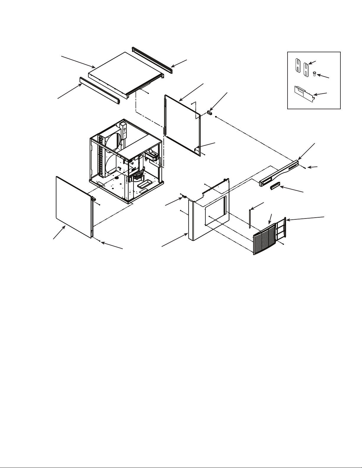
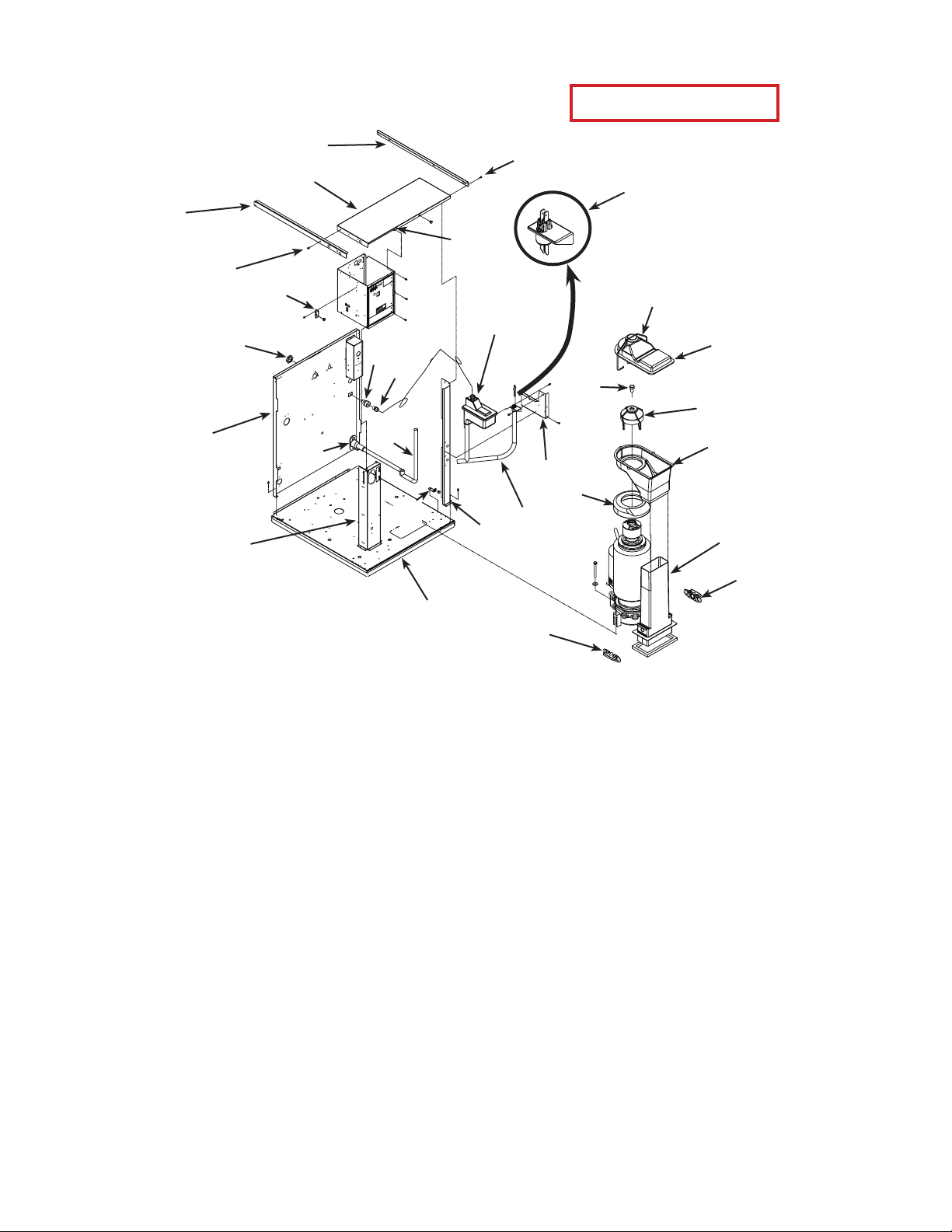
Exterior, N0422, F0522, N0622, F0822 A or B Series
1a
1
4d
1b
10
2
2a
8
4c
7
6
11
12
4a
4b
5
3
9
Item Part
Number Number Description
1 A39579-021 Top panel
1a 02-4221-01 Left trip strip*
1b 02-4221-02 Right trim strip*
2 A39445-021 Right side panel
2a 02-4215-01 Screw receptacle
side panel includes items 2a and 8
3 A39444-021 Left side panel, AC
A39444-022 Left side panel, WC, RC
side panel includes items 2a and 8
4 A39443-021 Front panel, AC
front panel includes items 4a, 4b, 4c, 5, 6, 7
A39443-022 Front panel, WC, RC
front panel includes 4a, 4b, 4c
4a 02-4214-01 Trim strip
4b 03-1735-03 Screw
4c 02-4284-01 Bezel
4d 02-4216-01 Gusset***
5 02-4212-01 Air lter
4
6 02-4224-01 Louver bracket
7 A39238-001 Filter bracket
8 A39571-001 Clip
9 03-1404-12 Screw
10 A30911-015 Machine straps
11 03-1405-15 Screw
12 02-4284-02 Bezel, partial window**
* Side trim strips discontinued mid 2011
** Item 12 discontinued from production 2/9/2012.
***Gusset discontinued May 2013.
December 2014
Page 2
Page 3
N0422, F0522, N0622, F0822, N0922, F1222, N1322, F1522
Service Parts
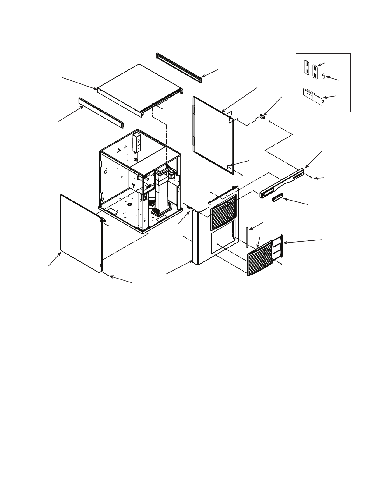
Exterior, N0922, F1222, N1322, F1522 A or B Series
1a
1b
1
2
2a
8
4d
7
6
10
11
12
4a
4b
4c
5
3
Item Part
9
Number Number Description
1 A39579-021 Top panel
1a 02-4221-01 Left trip strip*
1b 02-4221-02 Right trim strip*
2 A39445-022 Right side panel
2a 02-4215-01 Screw receptacle
side panel includes items 2a and 8
3 A39444-023 Left side panel, AC
A39444-024 Left side panel, WC, RC
side panel includes items 2a and 8
4 A39443-023 Front panel, AC
front panel includes items 4a, 4b, 4c, 5, 6, 7
A39443-024 Front panel, WC, RC
front panel includes 4a, 4b, 4c
4a 02-4214-01 Trim strip
4b 03-1735-03 Screw
4c 02-4284-01 Bezel
4
4d 02-4216-01 Gusset***
5 02-4212-01 Air lter
6 02-4224-01 Louver bracket
7 A39238-001 Filter bracket
8 A39571-001 Clip
9 03-1404-12 Screw
10 A30911-015 Machine straps
11 03-1405-15 Screw
12 02-4284-02 Bezel, partial window**
* Side trim strips discontinued mid 2011
** Item 12 discontinued from production 2/9/2012.
*** Gusset discontinued May 2013
December 2014
Page 3
Page 4
N0422, F0522, N0622, F0822, N0922, F1222, N1322, F1522
Service Parts
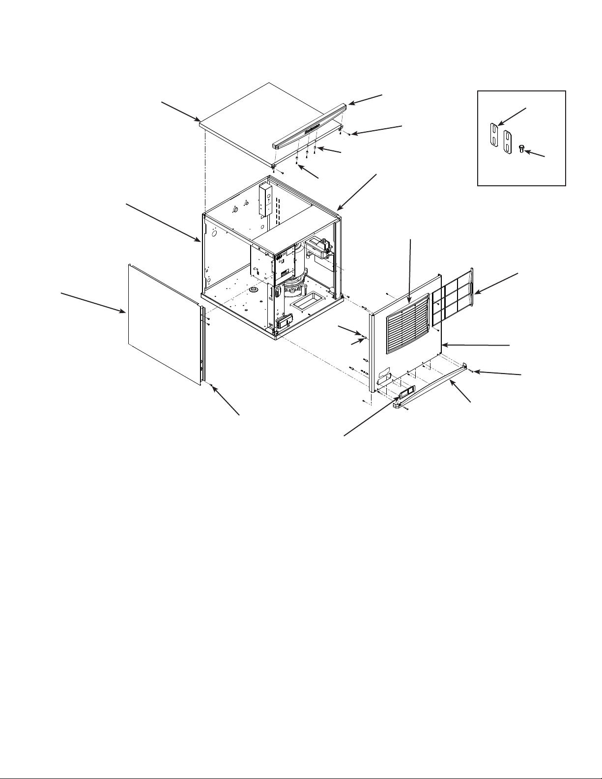
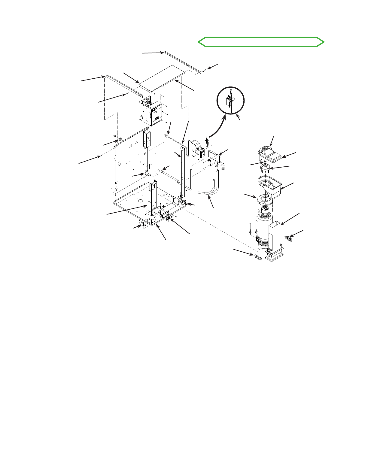
Exterior, N0422, F0522, N0622, F0822 D Series
13
14
1
10
11
11
10
2
15
12
16
3
4
5
6
7
Item Part
Number Number Description
12
9
1 A40309-022 Top panel, includes item 2
2 02-4819-02 Trim strip
3 A40335-021 Right side panel
4 02-4224-03 Louvers
5 02-4212-03 Air lter
6 A40308-025 Front panel, AC includes items 4, 5, 7, 8 and 9
A40308-026 Front panel, WC or RC. Includes items 4, 5, 7, 8 and 9
7 03-1735-03 Screw
8 02-4820-02 Tim strip
9 02-4821-02 Bezel, includes standard door
9a 02-4822-01 Door, bezel with handle
9b 02-4822-02 Door, bezel secure
10 02-4824-01 Spacer
11 03-3836-02 Screw
12 03-1404-10 Screw
13 A40310-023 Left side panel, AC
A40310-021 Left side panel, WC or RC
14 A39191-001 Back panel, WC or RC
15 A30911-015 Machine straps
16 03-1405-15 Screw
December 2014
Page 4
8
Page 5
N0422, F0522, N0622, F0822, N0922, F1222, N1322, F1522
Service Parts
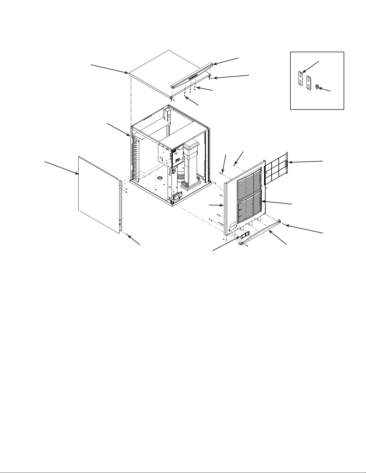
Exterior, N0922, F1222, N1322, F1522 D Series
13
2
1
12
10
11
14
10
6
11
4
10
11
5
12
Item Part
9
Number Number Description
1 A40309-022 Top panel, includes item 2
2 02-4819-02 Trim strip
3 A40335-022 Right side panel
4 02-4224-03 Louvers
5 02-4212-03 Air lter
6 A40308-028 Front panel, AC includes items 4, 5, 7, 8 and 9
A40308-029 Front panel, WC or RC. Includes items 4, 5, 7, 8 and 9
7 03-1735-03 Screw
8 02-4820-02 Tim strip
9 02-4821-02 Bezel, includes standard door
9a 02-4822-01 Door, bezel with handle
9b 02-4822-02 Door, bezel secure
10 02-4824-01 Spacer
11 03-3836-02 Screw
12 03-1404-10 Screw
13 A40310-025 Left side panel, AC
A40310-026 Left side panel, WC or RC
14 A39194-001 Back panel, WC or RC
15 A30911-015 Machine straps
16 03-1405-15 Screw
7
8
December 2014
Page 5
Page 6
N0422, F0522, N0622, F0822, N0922, F1222, N1322, F1522
Service Parts
Interior Cabinet, Water, and Chute Systems - Clear Reservoir Cover
21
19
26
20
18
27
22
28
1
26
Identication
reference: Water
2
Sensor in Hose. Used
until June 2012.
23
3
13
16
14
15
24
5
11
8
12
17
4
6
7
9
10
Item Part
Number Number Description
1 A39199-001 Channel, top right
2 02-4449-21 Water sensor
3 A34969-001 Bail clamp
4 02-2930-04 Chute cover
5 03-1405-52 Cap screw
6 02-3001-01 Ice sweep
7 02-3841-01 Ice chute
8 13-0929-01 Insulation collar, akers
13-0929-02 Insulation collar, nuggets
9 02-2929-03 Ice chute lower*
02-2929-04 Ice chute lower**
10 A37708-021 Bin control set (2)
11 A39200-001 Reservoir bracket
12 A39336-001 Evaporator inlet hose*
02-4338-01 Evaporator inlet hose**
13 02-3371-01 Water reservoir & valve
13a 02-3371-02 Float and arm only
13b 02-3266-03 Plunger/seat only
14 A39310-001 Drain hose*
02-4339-01 Drain hose**
15 16-1039-01 Connector, male
16 16-0835-01 Flare tting, male
29
10
17 A39201-001 Post, right front *
A39182-001 Post, right front **
18 A39196-001 Post, control box*
A39184-001 Post, control box**
19 A39191-001 Back panel, WC, RC*
A39194-001 Back panel, WC, RC**
20 03-1394-01 Pal nut
21 A39185-001 Channel, top left
22 A39181-001 Control box cover
23 03-3804-01 Receptacle
24 A38732-001 Panel mount
25 13-0895-01 Tubing, order 3
25a 16-0871-01 Brass insert, at oat valve
26 03-1531-01 Screw
27 A39025-001 Bracket
28 02-3692-21 Drain tting
29 02-4524-21 Base, ts Tecumseh or
Copeland RST - note RST used in B series
02-4524-22 Base, ts Copeland CS
* for N0422, F0522, N0622, F0822
** for N0922, F1222, N1322, F1522
December 2014
Page 6
Page 7
N0422, F0522, N0622, F0822, N0922, F1222, N1322, F1522
Service Parts
Interior Cabinet, Water, and Chute Systems - White Reservoir Cover & D Series
21
26
22
1
26
23
13
15
Identication Reference: Units with
this design also have water sensor
in the reservoir. Use began June 18,
2012 with N1322R-32A serial
number 12061320013354.
Item 12 changed August
2013, with serial number
13081320013114
2
3
20
19
25
18
24
Item Part
Number Number Description
1 A39199-001 Channel, top right
2 A39790-001 Water sensor
3 A34969-001 Bail clamp
4 02-2930-04 Chute cover
5 03-1405-52 Cap screw
6 02-3001-01 Ice sweep
7 02-3841-01 Ice chute
8 13-0929-01 Insulation collar, akers
13-0929-02 Insulation collar, nuggets
9 02-2929-03 Ice chute lower*
02-2929-04 Ice chute lower**
10 A37708-021 Bin control set (2)
11 A40029-001 Reservoir bracket
12 A40189-001 Evaporator inlet hose*
02-4752-01 Evaporator inlet hose**
13 A39789-001 Water reservoir & valve
13a 02-2217-02 Float and arm only
14 A40031-001 Drain hose*
02-4708-01 Drain hose**
15 16-1198-01 Fitting only
16
17
14
11
5
8
24a
12
27
10
4
6
7
9
10
16 02-4524-21 Base, ts Tecumseh or
Copeland RST - note RST used in B & D series
02-4524-22 Base, ts Copeland CS
17 A39201-001 Post, right front *
A39182-001 Post, right front **
18 A39196-001 Post, control box*
A39184-001 Post, control box**
19 A39191-001 Back panel, WC, RC*
A39194-001 Back panel, WC, RC**
20 03-1394-01 Pal nut
21 A39185-001 Channel, top left
22 A39181-001 Control box cover
23 03-3804-01 Receptacle, use discontinued
24 02-4823-01 Left panel mount
24a 02-4823-02 Right panel mount
25 02-3692-21 Drain tting
26 03-1531-01 Screw
27 11-0622-21 Lower light & sw panel
* for N0422, F0522, N0622, F0822
** for N0922, F1222, N1322, F1522
April 2015
Page 7
Page 8
N0422, F0522, N0622, F0822, N0922, F1222, N1322, F1522
Service Parts
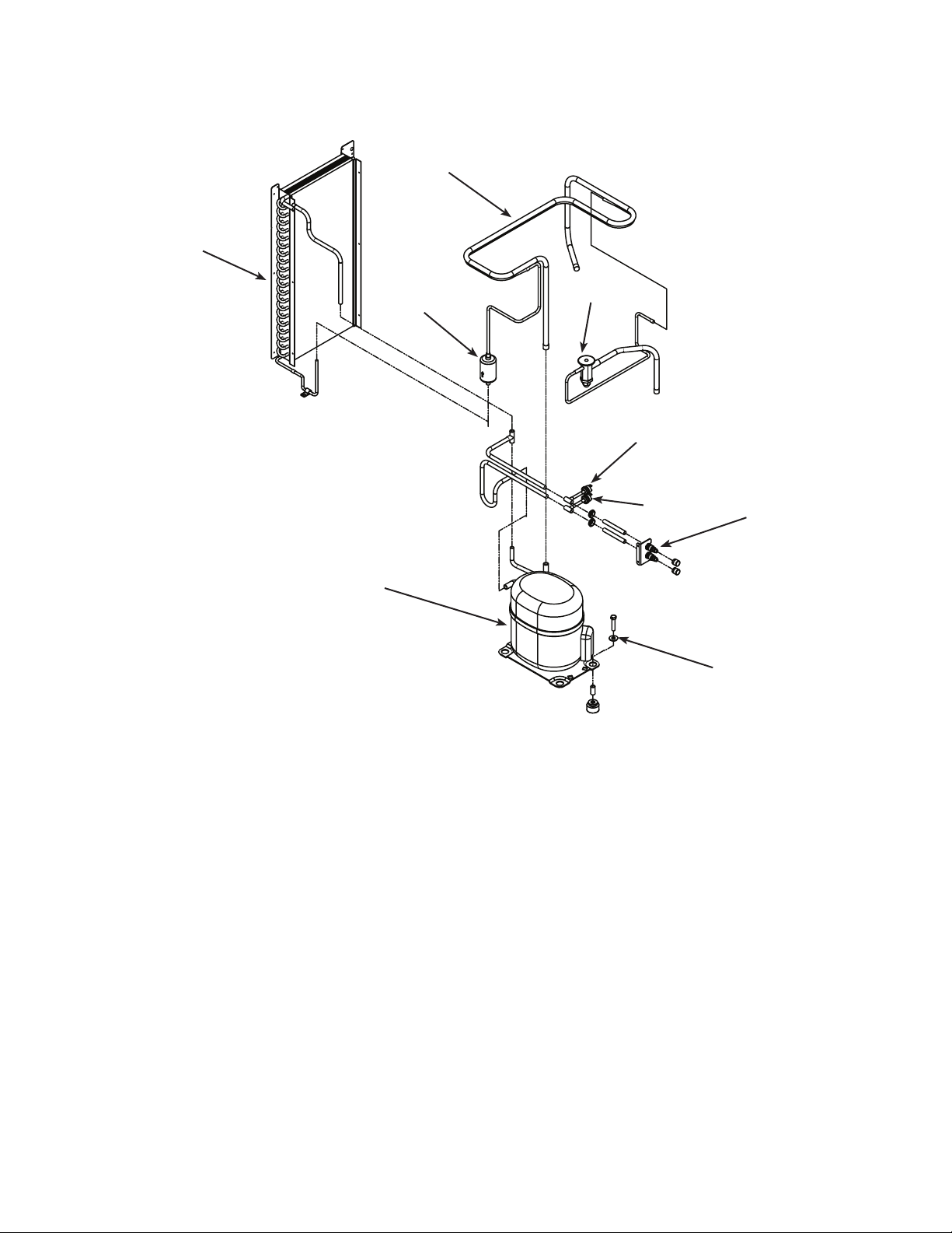
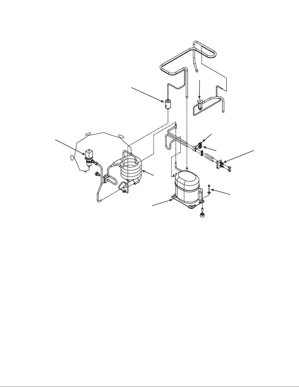
Refrigeration Condensing, Air Cooled
7
6
1, 1a
5
2
3
Compressors,
see page 18
Item Part
Number Number Description
1 16-1144-21 TXV, N0422, F0522
16-1144-22 TXV, N0622, F0822
16-1144-24 TXV, N0922, F1222
16-1144-23 TXV, N1322, F1522
1a 02-4406-01 Insulation, TXV
2 11-0501-22 High pressure cut out sw
3 11-0502-21 Low pressure cut out sw
4 16-1137-01 Access valve seat
4a 16-1139-01 Access valve core
4b 16-1140-01 Access valve cap
5 02-3319-01 Filter dryer
6 18-8890-01 Air cooled condenser, ts N0422, F0522, N0622, F0822
18-8935-01 Air cooled condenser, ts N0922, F1222,
18-8936-01 Air cooled condenser, ts N1322, F1522
7 A39249-001 Suction line for Tecumseh
A39249-002 Suction line for Copeland
4
Compressor hardware,
see page 18
December 2014
Page 8
Page 9
N0422, F0522, N0622, F0822, N0922, F1222, N1322, F1522
Service Parts
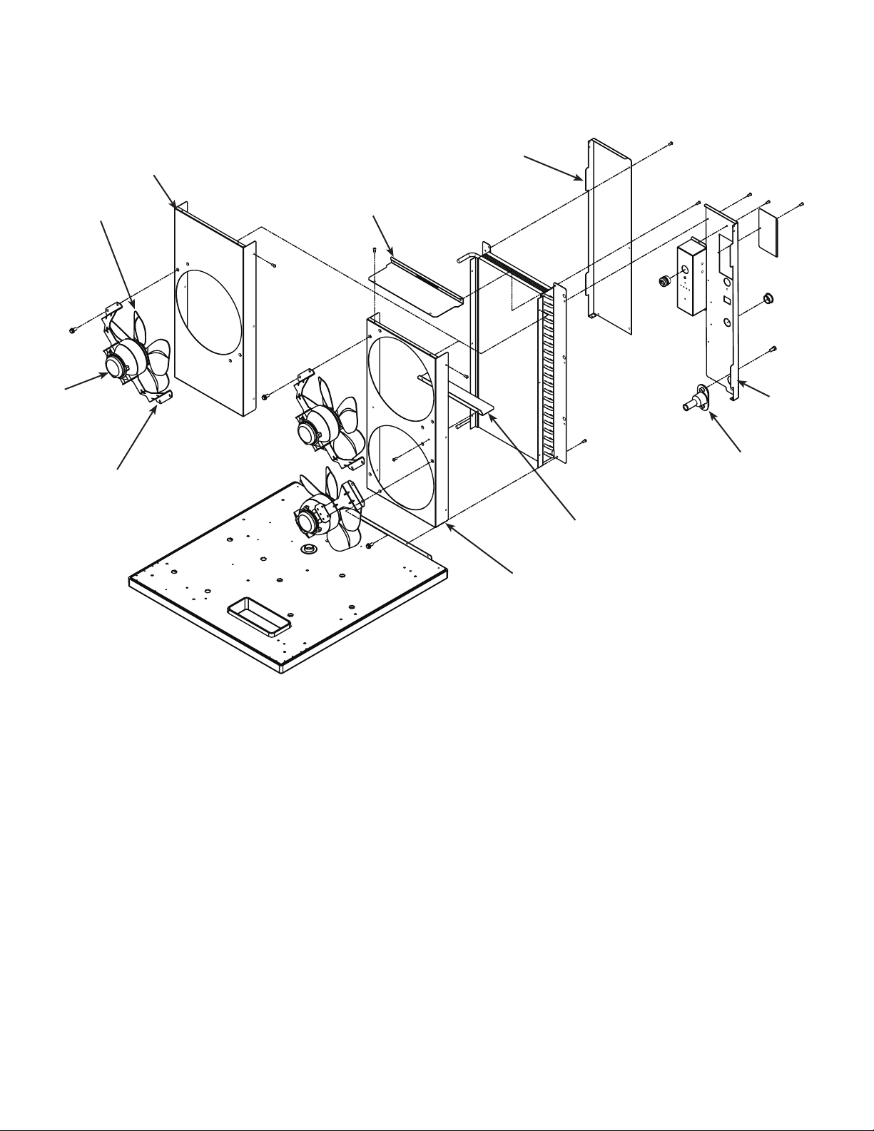
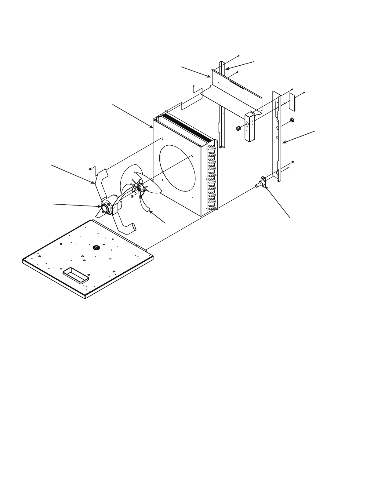
Condenser Fan Motor System - N0422, F0522, N0622, F0822
1
9
6
8
7
10
2
3
4
5
Item Part
Number Number Description
1 A39186-001 Condenser ange
2 A39187-001 Condenser ange
3 02-3692-21 Drain tting
4 A38675-001 Shroud divider
5 A39351-001 Shroud, N0622, F0822
6 18-8836-01 Fan blade
7 A38480-001 Bracket, fan motor
8 12-1681-23 Fan motor, 115 volt
12-1681-04 Fan motor, 208-230 volt/50 or 60 Hz
9 A39350-001 Shroud, N0422, F0522
10 A39352-001 Shroud top
December 2014
Page 9
Page 10
N0422, F0522, N0622, F0822, N0922, F1222, N1322, F1522
Service Parts
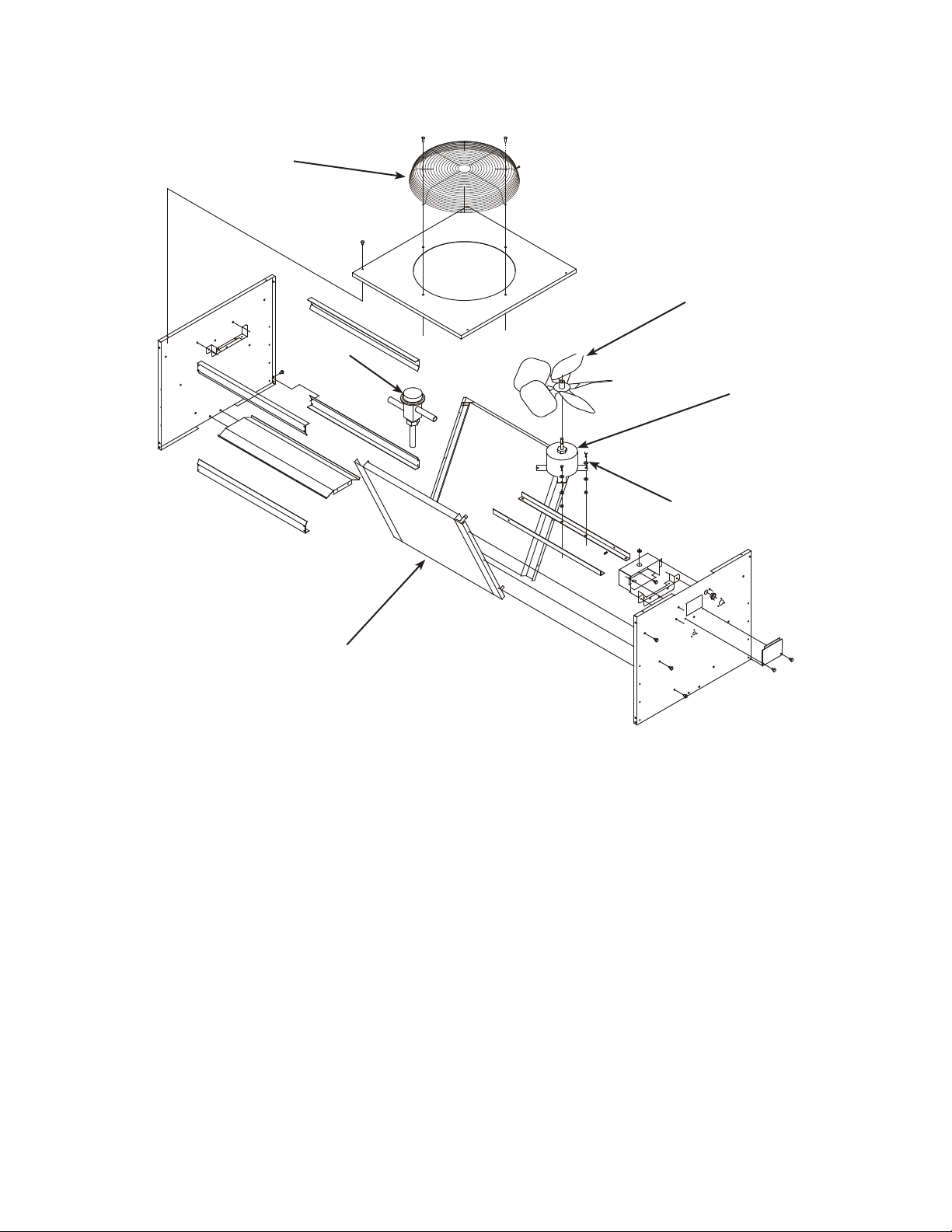
Condenser Fan Motor System, N0922, F1222, N1322, F1522
8
7
6
5
4
1
2
3
Item Part
Number Number Description
1 A39188-001 Condenser ange
2 A39189-001 Condenser ange
3 02-3692-21 Drain tting
4 18-8882-01 Fan blade
5 18-8927-01 Fan motor
6 A40156-001 Bracket, fan motor
7 A39193-001 Shroud
8 A39353-001 Shroud top
December 2014
Page 10
Page 11
N0422, F0522, N0622, F0822, N0922, F1222, N1322, F1522
Service Parts
Refrigeration Condensing, Water Cooled
1, 1a
8
2
6
3
7
Compressor hardware,
Compressors,
see page 18
Item Part
Number Number Description
1 16-1144-21 TXV, N0422, F0522
16-1144-22 TXV, N0622, F0822
16-1144-24 TXV, N0922, F1222
16-1144-23 TXV, N1322, F1522
1a 02-4406-01 Insulation, TXV
2 11-0501-22 High pressure cut out sw
3 11-0502-21 Low pressure cut out sw
4 16-1137-01 Access valve seat
4a 16-1139-01 Access valve core
4b 16-1140-01 Access valve cap
5 16-1154-22 Condenser drain tting
6 11-0608-21 Water regulating valve
7 18-8871-21 Condenser, water cooled ts N0422, F0522, N0622, F0822, N0922, F1222
18-8893-21 Condenser, water cooled ts N1322 and F1522
16-0874-01 Receiver, not shown, ts F1222W or N0922W
8 02-3319-02 Filter dryer
see page 18
4
December 2014
Page 11
Page 12
N0422, F0522, N0622, F0822, N0922, F1222, N1322, F1522
Service Parts
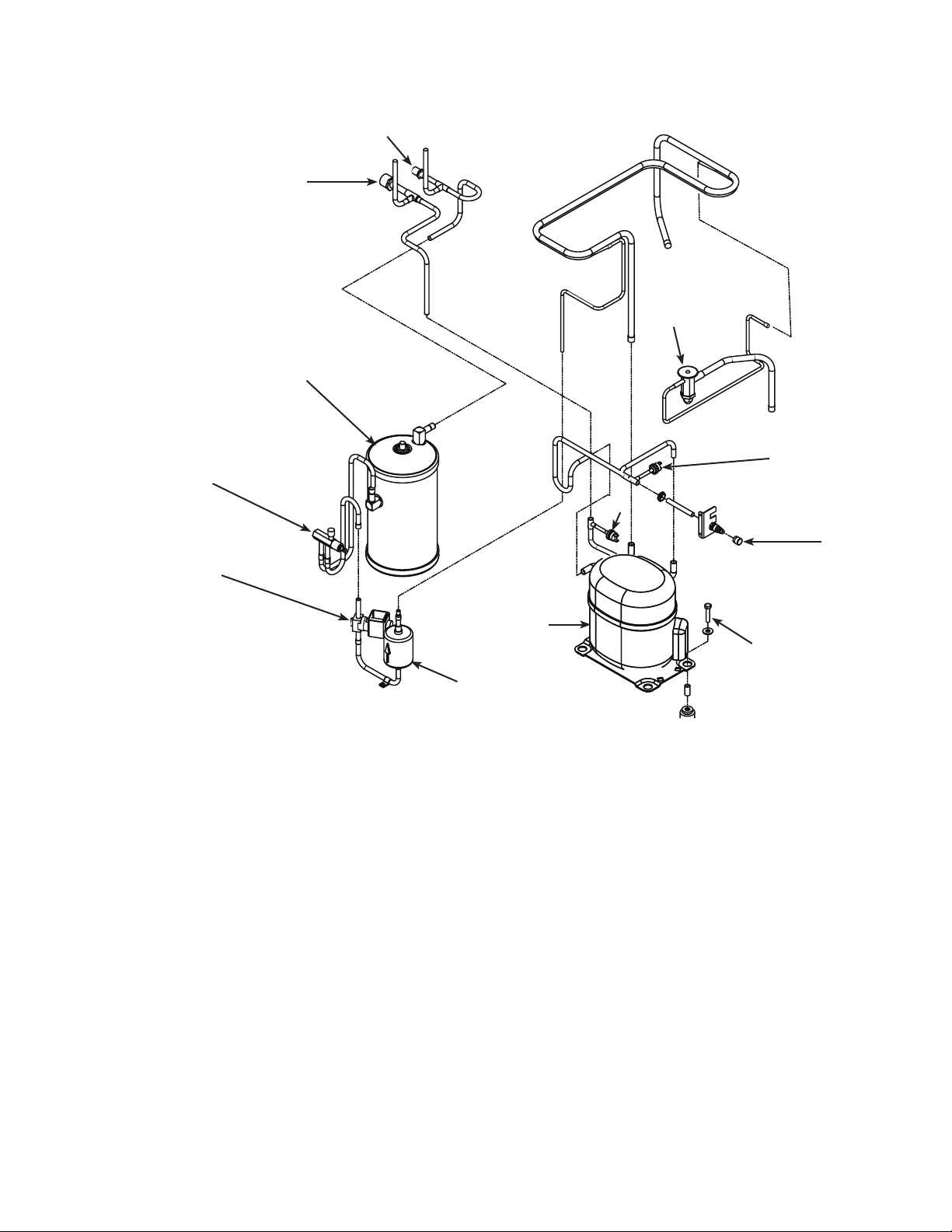
Refrigeration Condensing, Remote Cooled
10
9
1, 1a
8
2
7
6
Compressors,
see page 18
Item Part
Number Number Description
5
1 16-1144-22 TXV, N0622, F0822
16-1144-24 TXV, N0922, F1222
16-1144-23 TXV, N1322, F1522
1a 02-4406-01 Insulation, TXV
2 11-0502-21 Low pressure cut out sw
3 11-0501-22 High pressure cut out sw
4 16-1137-01 Access valve seat
4a 16-1139-01 Access valve core
4b 16-1140-01 Access valve cap
5 02-3319-02 Filter dryer
6 11-0493-01 Liquid line solenoid valve, 208-230 volt, 50/60 Hz
12-2719-22 230 volt coil
11-0493-02 Liquid line solenoid valve, 115 volt
12-2719-21 115 volt coil
12-2733-30 LLV/HGV rebuild kit
7 16-1030-01 Receiver outlet valve
8 16-1176-01 Receiver
8a A37211-001 Bracket, receiver top
8b A37212-001 Bracket, receiver bottom
9 16-0850-01 Discharge quick connect
10 16-0850-03 Liquid quick connect
3
4
Compressor hardware,
see page 18
December 2014
Page 12
Page 13
N0422, F0522, N0622, F0822, N0922, F1222, N1322, F1522
Service Parts
Remote Condenser - ERC111 or ERC311
1
2
5
3
6
Item Part
Number Number Description
1 02-3575-01 Fan guard
2 18-8816-01 Fan blade
3 12-2651-01 Fan motor - ERC311 (208-230 volt)
12-2651-02 Fan motor - ERC111 (115 volt)
4 03-1405-08 Screw
5 11-0422-22 Headmaster
6 18-8827-01 Coil
Not shown:
NS1 A37169-001 Leg
NS2 A37170-001 Leg brace
NS3 03-1645-01 Screw for legs
NS4 16-0850-01 Quick disconnect, discharge
NS5 16-0850-03 Quick disconnect, liquid
NS6 16-1057-01 Line set tube end, discharge
NS7 16-1057-02 Line set tube end, liquid
4
December 2014
Page 13
Page 14

N0422, F0522, N0622, F0822, N0922, F1222, N1322, F1522
Service Parts
Nugget Evaporator System, N0422, N0622, N0922, N1322
1
11
2
3
4
5
6
7
8
9
10
12
15
17
15
14
16
18
13
Item Part
Number Number Description
1 03-1405-52 Cap screw
2 02-3001-01 Ice sweep
3 13-0871-01 Water shed
4 02-2978-01 Lip seal
5 02-3128-20 Cover, includes item 4
6 13-0617-54 O-ring
7 08-0660-01 Auger stud
8 A34559-020 Bearing
9 02-2977-01 Lip seal
10 13-0617-52 O-ring - to chute
11 03-1544-08 Screw, socket head
16
20
21
12 A32900-020 Nugget breaker assembly,
includes items 3,4,5,6,8,9 and 13
13 13-0617-45 O-ring
14 A38071-021 Auger, N0422, N0622
A38071-022 Auger, N0922, N1322
15 02-0929-23 Water seal
16 02-4350-21 Evaporator, N0422, N0622
02-4352-21 Evaporator, N0922, N1322
16a 03-1405-41 Cap screw to gear box
17 02-4358-01 Collar
18 A32777-001 Retaining ring
19 02-4663-01 Water shed
20 02-3837-01 Drip pan
21 13-0704-00 Gasket
December 2014
Page 14
Page 15

N0422, F0522, N0622, F0822, N0922, F1222, N1322, F1522
Service Parts
Evaporator System, Flakers F0522, F0822, F1222, F1522
1
2
17
5
14
3
12
7
10
4
6
8
9
11
13
15
16
18
20
18
19
21
22
23
Item Part
Number Number Description
1 03-1405-52 Cap screw
2 02-3001-01 Ice sweep
3 13-0871-01 Water shed
4 02-2978-01 Lip seal
5 02-3128-20 Cover, includes item 4
6 13-0617-54 O-ring
7 08-0660-01 Auger stud
8 A34559-020 Bearing
9 02-2977-01 Lip seal
10 13-0617-52 O-ring, to chute
11 03-1403-27 Screw
12 02-2916-01 Slotted collar
13 13-0617-49 O-ring, under slotted collar
14 03-1544-08 Screw, socket head
December 2014
24
15 A34505-020 Flaker breaker assembly,
includes items 3,4,5,6,8,9, and 16
16 1 3-0617-45 O-ring
17 A38071-021 Auger, F0522, F0822
A38071-022 Auger, F1222, F1522
18 02-0929-23 Water seal
19 02-4350-21 Evaporator, F0522, F0822
02-4352-21 Evaporator, F1222, F1522
19a 03-1405-41 Cap screw to gear box
20 02-4358-01 Collar
21 A32777-001 Retaining ring
22 02-4663-01 Water shed
23 02-3837-01 Drip pan
24 13-0704-00 Gasket
Page 15
Page 16
N0422, F0522, N0622, F0822, N0922, F1222, N1322, F1522
Service Parts
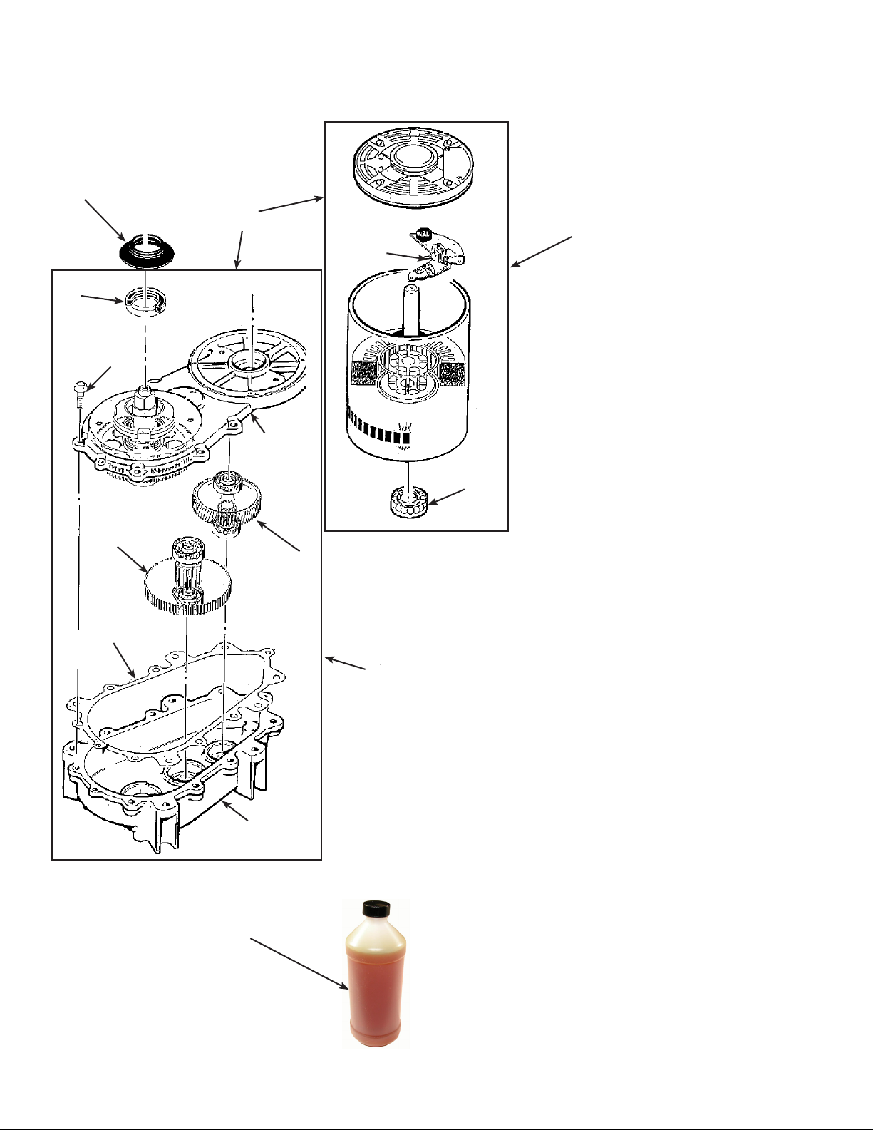
Gear Reducer and Motor
4
14
1
2
5
7
6
9
10
Oil Charge is 14 Oz.
13
11
3
8
12
December 2014
Page 16
Item Part
Number Number Description
1 12-2430-21+ Drive motor, 115 volt
12-2430-22+ Drive Motor, 208-230 volt
2 12-2430-44 Start switch
3 12-2430-29 Bearing
4 02-4663-01 Water Shed
5 A32379-029* Seal
6 A32379-022 Gearcase Cover*
7 A32379-026 Bolt
8 A32379-024 First Gear & Bearings
9 A32379-023 2nd Gear & Bearings
10 A32379-021 Gasket
11 A32379-020 Gear Case
12 A33220-030 Gearcase kit, assembled
w/out motor, includes item 13
13 A32379-027 Oil, 1 Container
14 A33220-021** Complete 115 volt
A33220-022** Complete 208-230 volt
* Cover includes output shaft, seal, gear and
bearings.
If water has owed thru the seal, the gearcase cover
assembly should be replaced, not just the seal.
** Includes items 1, 12, and is charged with gear oil.
Page 17
N0422, F0522, N0622, F0822, N0922, F1222, N1322, F1522
Service Parts
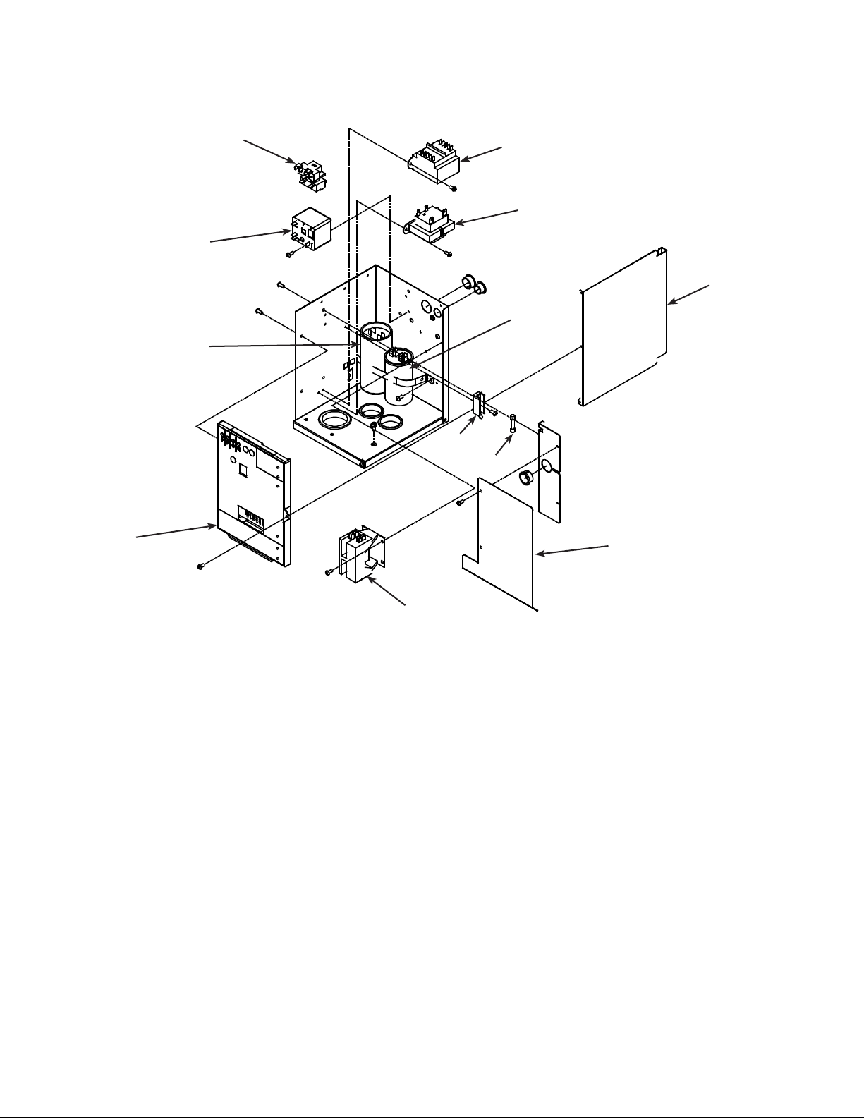
Electrical & Control Box
7, 7a, 7b
10
9
8
12
1
2
4
3
11
5
6
Item Part
Number Number Description
1 12-2639-01 Transformer, 50 Hz
2 12-2924-01 Transformer, 115 v
12-2924-02 Transformer, 208-230 60 Hz
3 see page 15 Run capacitor
4 A39198-001 Side cover
5 A39216-001 Shield
6 12-2469-03 Contactor, 115 volt
12-2469-02 Contactor, 208-230 volt 60 Hz, single phase
12-2533-02 Contactor, 3 phase
7 11-0575-22 Controller for A or B series.
11-0623-21 Controller for Prodigy Plus D series and all prior
7a 02-4407-01 Graphic overlay
7b 02-4076-01 Control box door
8 see next page Start capacitor
9 see next page Potential relay
10 see next page Start relay
11 12-2686-01 Fuse, 50 Hz only
12 12-2687-01 Fuse block, 50 Hz only
December 2014
Harnesses (not shown)
NS1 12-2976-01 Low voltage harness
NS2 12-2994-01 High voltage harness, AW
NS3 12-2966-01 High voltage harness, Rem
Page 17
Page 18

N0422, F0522, N0622, F0822, N0922, F1222, N1322, F1522
Service Parts
Compressors
Model Series Electrical Compressor Overload Relay Start Cap Run Cap
N0422, F0522 -1 A or D 115/60/1 18-8929-21 18-8929-23 18-1903-64 18-1901-63 not used
N0622, F0822 -1 A 115/60/1 18-8921-21 18-8921-23 18-1903-68 18-1901-55 18-1902-45
N0622, F0822 -32 A 208-230/60/1 18-8921-22 18-8774-28 18-1903-67 18-1901-56 18-1902-68
N0622, F0822 -6 A 230/50/1 18-8921-26 18-8774-27 18-1903-66 18-1901-56 18-1902-68
N0622, F0822 -1 B* or D 115/60/1 18-8949-21 18-8949-50 18-1903-44 18-1901-65 18-1902-64
N0622, F0822 -32 B* or D 208-230/60/1 18-8949-22 18-8949-51 18-1903-54 18-1901-66 18-1902-30
N0622, F0822 -6 B* or D 230/50/1 18-8949-23 18-8949-52 18-1903-70 18-1901-52 18-1902-65
N0922, F1222 -32 A 208-230/60/1 18-8922-22 18-8922-27 18-1903-44 18-1901-66 18-1902-45
N0922, F1222 -3 A 208-230/60/3 18-8813-25 Internal - - N0922, F1222 -6 A 230/50/1 18-8922-26 Internal 18-1903-69 18-1901-66 18-1902-71
N0922, F1222 -32 B** or D 208-230/60/1 18-8955-22 Internal 18-1903-54 18-1901-20 18-1902-67
N0922, F1222 -3 B** or D 208-230/60/3 18-8955-23 18-8955-53 - - N0922, F1222 -6 B** or D 230/50/1 18-8955-26 Internal 18-1903-71 18-1901-66 18-1902-63
N1322, F1522 -32 A or D 208-230/60/1 18-8749-22 Internal 18-1903-46 18-1901-48 18-1902-70
N1322, F1522 -6 A or D 230/50/1 18-8749-27 Internal 18-1903-33 18-1901-48 18-1902-70
* B series production began July 2011 ** B series production began April 2014
Compressor Mounting Hardware
Model Bolt Grommet Washer Sleeve
N0422, F0522,
N0622, F0822
N0622, F0822 B 03-1405-20 18-2200-28 03-1407-07 18-2200-27
N0922, F1222 -32 03-1405-20 18-4700-28 03-1407-07 18-0108-41
N0922, F1222 -3 03-1405-20 18-2300-27 03-1407-07 18-2300-26
N1322, F1522 -32 03-1405-20 18-2300-27 03-1407-07 18-2300-26
03-1405-20 18-4700-28 03-1407-07 18-0108-41
Crankcase Heaters
Model Series Voltage Heater
N0622R-1, F0822R-1 A 115 12-2942-01
N0622R-32, F0822R-32 A 230 12-2942-02
N0622R-1, F0822R-1 B or D 115 12-3043-01
N0622R-32, F0822R-32,
N0922R, F1222R -3 or -32
N0922R-32, F1222R-32 A 230 12-2942-02
N0922R-3, F1222R-3 A 230, 3 phase 12-3043-03
N1322R -32, -3, F1522R-32, -3 A or D 230 12-3043-03
B or D 230 12-3043-02
December 2014
Page 18
Page 19

N0422, F0522, N0622, F0822, N0922, F1222, N1322, F1522
CENTRIFUGAL
Service Parts
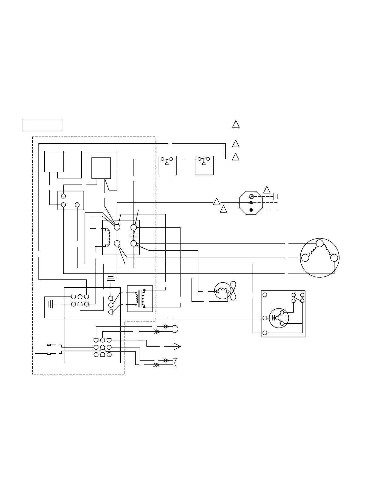
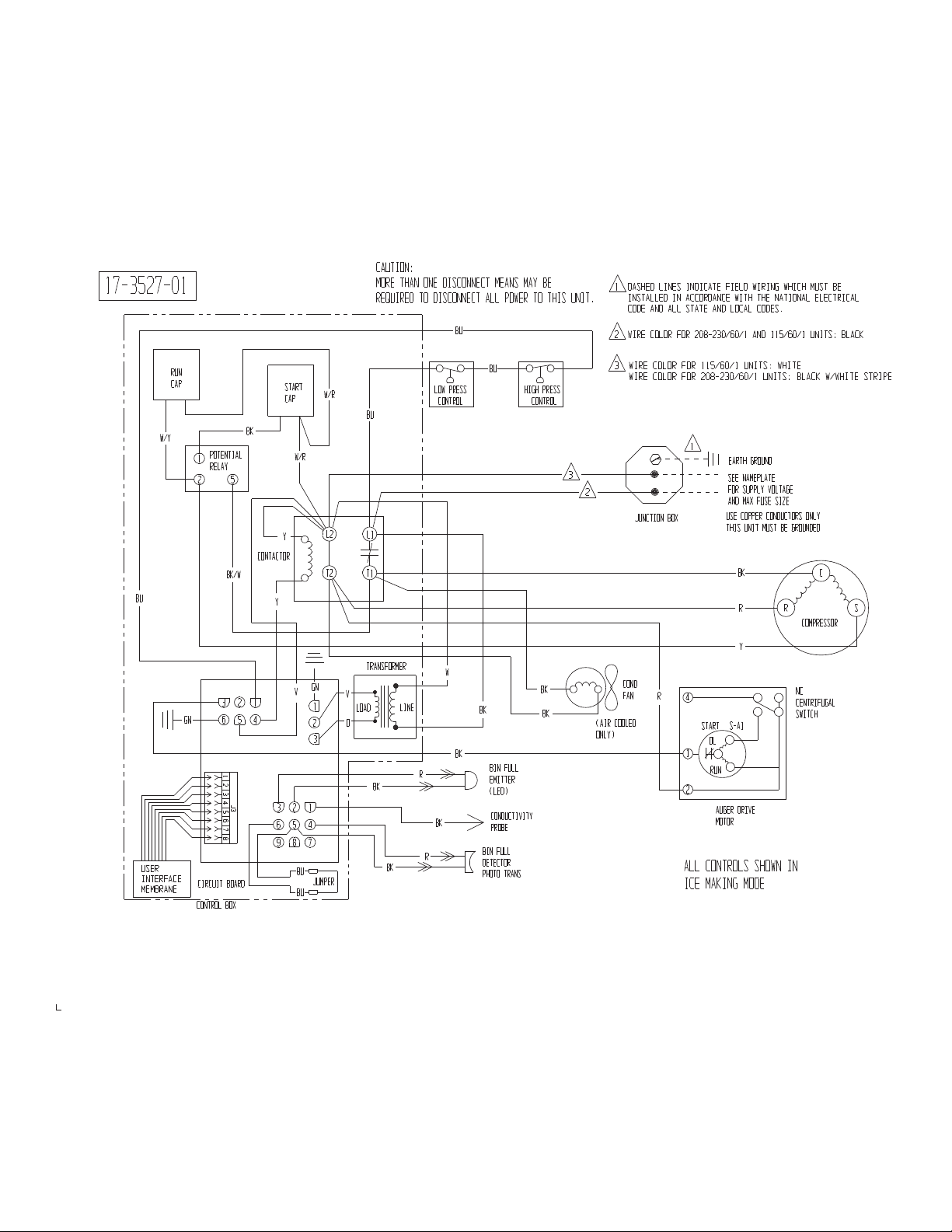
Wiring Diagram N0422 and F0522 A Series
17-3211-01
CURRENT
1
RELAY
BU
GN
JUMPER
BU
BU
CONTROL BOX
V
2
M
LS
3
CIRCUIT BOARD
1 DASHED LINES INDICATE FIELD WIRING WHICH MUST BE
INSTALLED IN ACCORDANCE WITH THE NATIONAL ELECTRICAL
CODE AND ALL STATE AND LOCAL CODES.
BU
BU
START
CAP
BU
BK
R
L2
L1
T2
T1
TRANSFORMER
V
LOAD
O
BK
BK
41256
Y
CONTACTOR
Y
321
6 5 4
9 8 7
GN
V
1
2
3
LINE
LOW PRESS
CONTROL
W
BK
BK
R
BK
R
BIN FULL
EMITTER
(LED)
CONDUCTIVITY
PROBE
BIN FULL
DETECTOR
PHOTO TRANS
HIGH PRESS
CONTROL
3
BK
BK
2 WIRE COLOR FOR 208-230/60/1 AND 115/60/1 UNITS: BLACK
3 WIRE COLOR FOR 115/60/1 UNITS: WHITE
WIRE COLOR FOR 208-230/60/1 UNITS: BLACK W/WHITE STRIPE
1
2
JUNCTION BOX
COND
FAN
(AIR COOLED
ONLY )
R
EARTH GROUND
SEE NAMEPLATE
FOR SUPPLY VOLTAGE
AND MAX FUSE SIZE
USE COPPER CONDUCTORS ONLY
THIS UNIT MUST BE GROUNDED
BK
R
Y
4
1
2
START
OL
RUN
AUGER DRIVE
MOTOR
C
COMPRESSOR
S-A1
ALL CONTROLS SHOWN IN
ICE MAKING MODE
SR
NC
SWITCH
December 2014
Page 19
Page 20

N0422, F0522, N0622, F0822, N0922, F1222, N1322, F1522
Service Parts
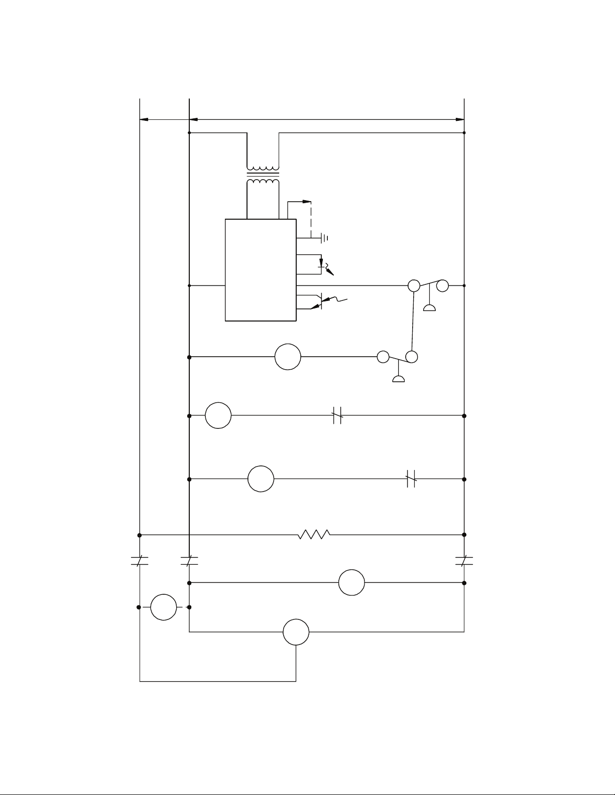
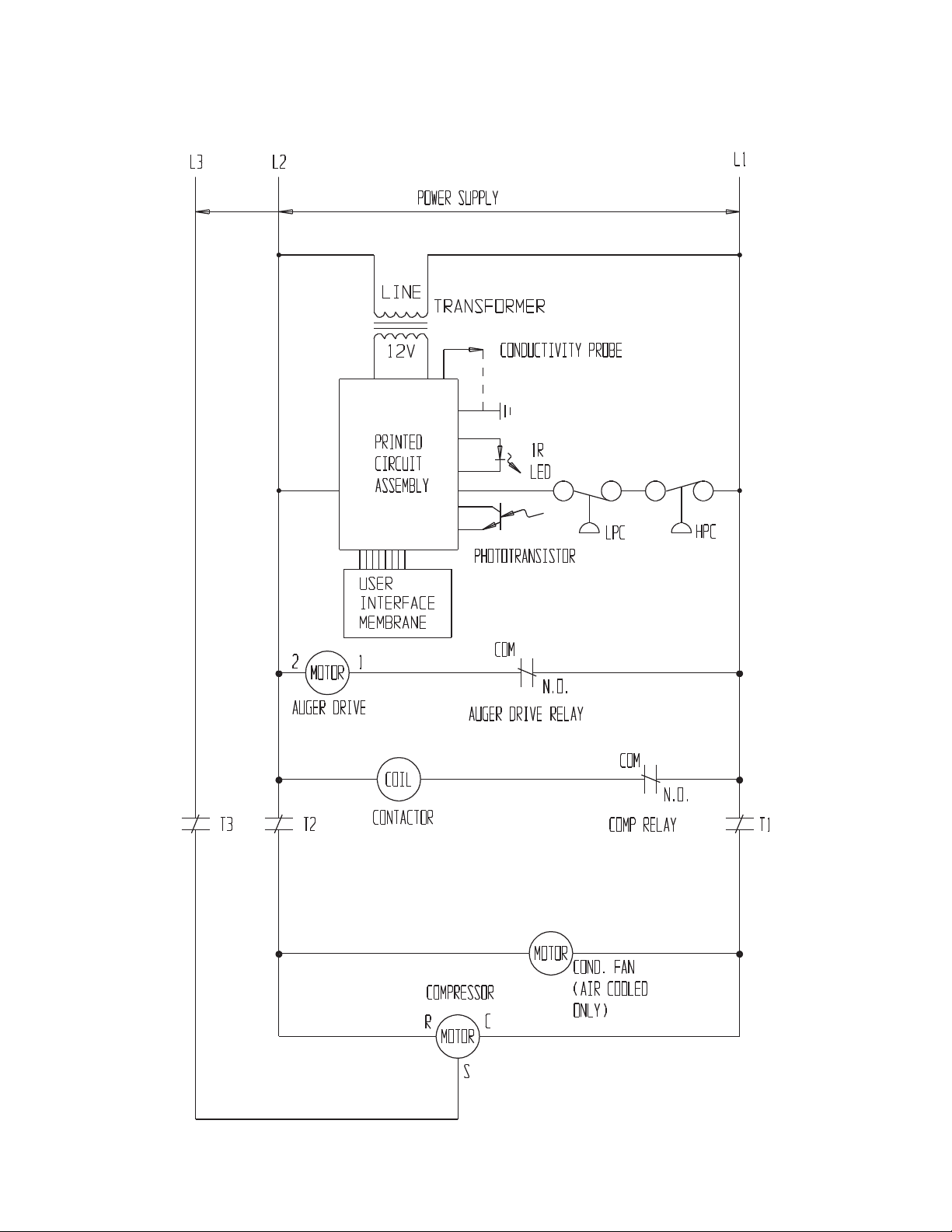
Schematic Diagram N0422 or F0522 A Series
L2
T2
2
MOTOR
AUGER DRIVE
1
POWER SUPPLY
LINE
12V
PRINTED
CIRCUIT
ASSEMBLY
C0IL
CONTACTOR
TRANSFORMER
CONDUCTIVITY PROBE
PHOTOTRANSISTOR
COM
AUGER DRIVE RELAY
1R
LED
N.O.
LPC
L1
HPC
COM
N.O.
COMP RELAY
T1
START
CAP
RUN
CAP
POT
RELAY
COMPRESSOR
R
MOTOR
21
December 2014
Page 20
MOTOR
FAN
(AIR COOLED ONLY )
C
S
C0IL
2
POT RELAY
5
Page 21
N0422, F0522, N0622, F0822, N0922, F1222, N1322, F1522
Service Parts
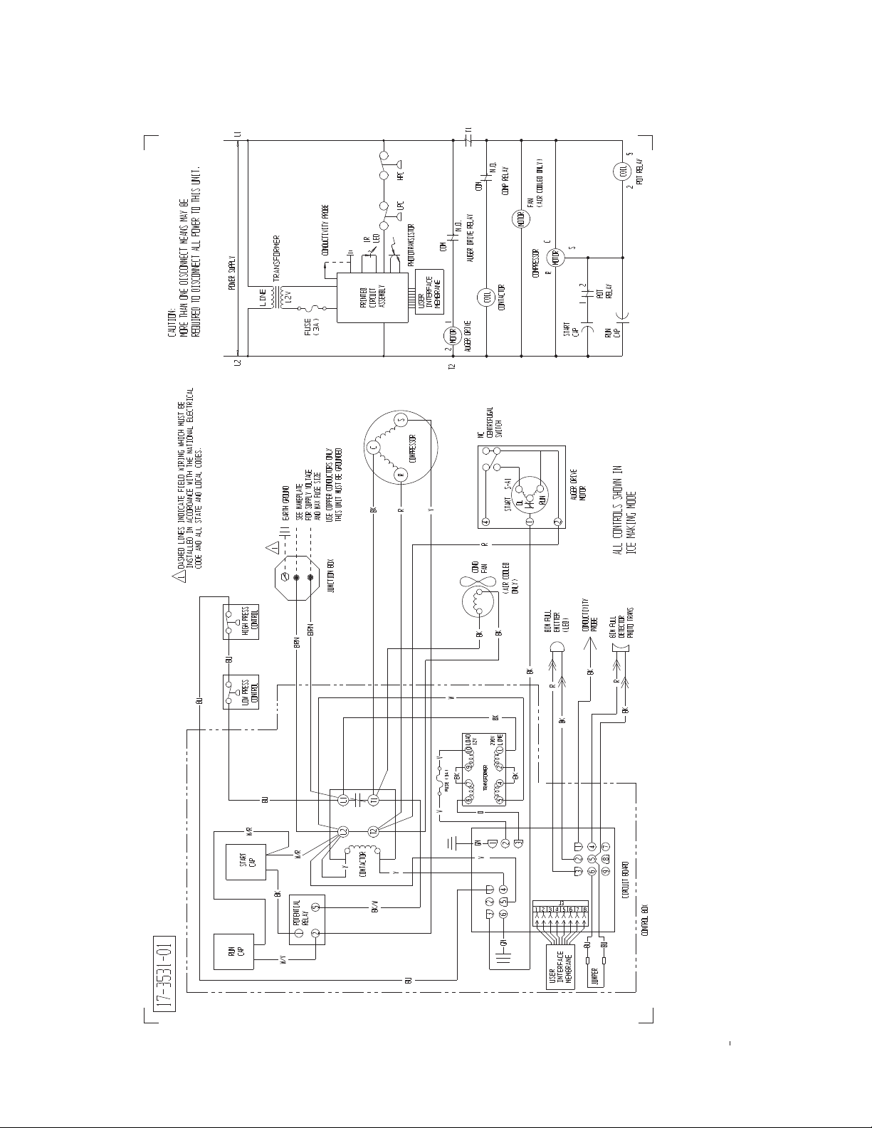
Wiring Diagram N0622, F0822, N0922, F1222, N1322 or F1522 Single Phase A or B Series
CAUTION:
17-31 99-01
MORE THAN ONE DI SCONNECT ME ANS MA Y BE
REQUIRED TO DI SCONNE CT AL L POWE R TO THIS UNIT.
BU
1 DAS HED LI NES IN DI CATE FIELD WIRING WHIC H MUST BE
INSTALLED IN AC CORDANCE WITH THE NATION AL ELE CTRICAL
COD E AND ALL ST ATE AN D LOCA L CODE S.
2 WI RE CO L OR FOR 20 8-230 / 60/1 AND 115/6 0/1 UNITS: BLAC K
BU
JUMP ER
W/Y
RUN
CAP
1
GN
BU
BU
CONT ROL BOX
POTENT IAL
RELAY
52
BK/W
3
6
BK
CONT ACTOR
1
2
5
4
CI RCUI T BOARD
START
CAP
W/R
Y
Y
V
321
6
5 4
987
GN
1
2
3
W/R
L2
T2
V
LOAD
O
BU
L1
T1
TRANSFOR ME R
BK
BK
LI NE
R
R
LOW PRESS
CONT ROL
W
BK
BK
BU
HI GH PRESS
CONT ROL
BK
BI N FULL
EMITTER
(LED)
CONDUCTIVITY
PROBE
BIN FULL
DETECTOR
PHOTO TRANS
BK
BK
3
3 WI RE COLOR FOR 115/ 60/1 UNITS: WHI TE
WI RE COLOR FOR 208- 230/ 60/1 UNITS: BLACK W/WHI TE STRI PE
1
EARTH GR OUND
SEE NAME PL ATE
2
(AIR COOL ED
ONLY)
JUNC TI ON BOX
COND
FAN
R
FOR SUPPLY VOLTAGE
AND MA X FUSE SI ZE
US E COPPER CONDUCTORS ONLY
THIS UNIT MU ST BE GR OUNDED
4
S- A1
START
OL
1
RUN
2
AUGE R DR IVE
MO TOR
BK
R
Y
C
COMP RESSOR
NC
CE NT RI FUGA L
SWITCH
ALL CONTROLS SHOWN IN
I CE MAKING MODE
SR
December 2014
Page 21
Page 22

N0422, F0522, N0622, F0822, N0922, F1222, N1322, F1522
Service Parts
Schematic Diagram N0622, F0822, N0922, F1222, N1322 or F1522 Single Phase A or B Series
L2
POWER SUPPLY
LINE
12V
PRINTED
CI RCUIT
AS SEMB LY
T RANSFORMER
CONDUC TI VI TY PROB E
1R
LED
PHOT OT RANS ISTOR
LPC
L1
HPC
T2
2
MO TOR
AUGE R DR IVE
START
CAP
RUN
CAP
1
C0IL
CONT ACTOR
21
POT
RELAY
COM
AUGE R DR IVE RE LAY
COMP RE SSOR
R
MO TOR
S
C
N. O.
MO TOR
COM
N. O.
COMP RELAY
FAN
(AIR COOL ED ONLY)
C0IL
2
POT RELAY
T1
5
December 2014
Page 22
Page 23

N0422, F0522, N0622, F0822, N0922, F1222, N1322, F1522
Service Parts
Wiring Diagram N0922, F1222, N1322 or F1522 Three Phase A or B Series
NOTE:
1
BU
PUMP DOWN
CONT ROL
V
BU
HIGH PRESS
CONT ROL
BU
Y
L2L3
L1
DASHED LINES INDICATE FI E LD WIRI NG
WH ICH MUST BE I NSTALL ED
IN ACCO R DANCE WI TH TH E NATIONAL
E LECTRICA L CODE US I NG A MINIMUM OF 14 AWG WIRE
BK
BK
BK
1
J UNCTION BOX
E ARTH GR OUND
S EE NAMEP LATE
FOR SUPPLY VOLT AGE
AND MAX F USE SIZE
USE COPPER CONDUCTORS ONLY
THIS UNIT MUST BE GROUNDED
JUMPER
GN
BU
BU
3
1
2
56
4
CIRC UIT BOARD
321
6 5 4
9
CONT ROL BOX
8 7
GN
1
2
3
Y
TRANSF ORME R
V
LOAD L INE
O
BK
BK
T1
T2T3
W
BK
R
BK
R
BIN F ULL
EMITTER
( LED)
CONDUC TI VI TY
PROB E
BI N FULL
DE TECT OR
(PHOTO TRANS)
BK
BK
BK
R
R
R
R
COND
FAN
(AIR COOLED
ONLY)
AL L CONT ROLS SHOWN IN
ICE MA KI NG MO DE
4
1
2
S TART
OL
RUN
GEAR MOTOR
S -A1
T1
COMPRESSOR
NC
CENTRI FUGA L
SWITCH
T3T2
December 2014
Page 23
Page 24

N0422, F0522, N0622, F0822, N0922, F1222, N1322, F1522
L3
L2
L1
Service Parts
Schematic Diagram N0922, F1222, N1322 or F1522 Three Phase A or B Series
POWER SU P PLY
2
1
MOTOR
AUGE R DRIVE
L INE
TRANSF ORME R
12V
PRINTED
CIRCUIT
ASSE MBLY
COND UCTIVITY PR OBE
1R
LED
PHOT OTRANS IS TOR
COM
N.O.
AUGER DR I VE RELAY
LPC
HPC
T3
T2
COIL
CONTACTOR
COMPRESSOR
R
MOTOR
December 2014
Page 24
COM
N.O.
COMP RELAY
T1
MOTOR
COND. FAN
(AIR COOLED
C
ONLY)
S
Page 25

N0422, F0522, N0622, F0822, N0922, F1222, N1322, F1522
Service Parts
Wiring Diagram N0622, F0822, N0922, F1222, N1322, F1522 Remote Single Phase A or B Series
17-3200-01
1
POTENTIAL
RELAY
GN
JUMPER
BU
BU
Y
LIQ LINE
SOLENOID
W/Y
52
BK
BU
3
41256
CIRCUIT BOARD
CONTROL BOX
GN
1
2
3
321
6 5 4
9 8 7
PUMP DOWN
CONTROL
BK
V
BK/W
Y
TRANSFORMER
V
LOAD
O
BK
BK
RUN
CAP
Y
Y
W
BU
BU
LINE
R
BK
R
BIN FULL
EMITTER
(LED)
CONDUCTIVITY
PROBE
BIN FULL
DETECTOR
PHOTO TRANS
START
CAP
W/R
BK
W/R
BU
L1L2
T1T2
R
BK
BK
R
HIGH PRESS
CONTROL
BK
BK
JUNCTION BOX
1 DASHED LINES INDICATE FIELD WIRING WHICH MUST BE
INSTALLED IN ACCORDANCE WITH THE NATIONAL ELECTRICAL
CODE AND ALL STATE AND LOCAL CODES.
2 WIRE COLOR FOR 208-230/60/1 AND 115/60/1 UNITS: BLACK
3 WIRE COLOR FOR 115/60/1 UNITS: WHITE
WIRE COLOR FOR 208-230/60/1 UNITS: BLACK W/WHITE STRIPE
CAUTION:
MORE THAN ONE DISCONNECT MEANS MAY BE
REQUIRED TO DISCONNECT ALL POWER TO THIS UNIT.
BK
3
2
C
SR
4
S-A1
START
OL
1
RUN
2
GEAR MOTOR
1
1
JUNCTION BOX
EARTH GROUND
1
SEE NAMEPLATE
FOR SUPPLY VOLTAGE
AND MAX FUSE SIZE
USE COPPER CONDUCTORS ONLY
THIS UNIT MUST BE GROUNDED
NC
CENTRIFUGAL
SWITCH
COND
FAN
ALL CONTROLS SHOWN IN
ICE MAKING MODE
December 2014
Page 25
Page 26

N0422, F0522, N0622, F0822, N0922, F1222, N1322, F1522
Service Parts
Schematic N0622, F0822, N0922, F1222, N1322, F1522 Remote Single Phase A or B Series
L2
2
AUGER DRIVE
MOTOR
1
POWER SUPPLY
LINE
12V
PRINTED
CIRCUIT
ASSEMBLY
COIL
CONTACTOR
L1
TRANSFORMER
CONDUCTIVITY PROBE
1R
LED
HPC
PHOTOTRANSISTOR
PDC
COM
N.O.
AUGER DRIVE RELAY
REM COND FAN
START
CAP
RUN
CAP
SOL
LIQUID LINE
MOTOR
POT
RELAY
CRANKCASE HEATER
COMPRESSOR
R
MOTOR
21
COM
N.O.
COMP RELAY
T1
C
S
C0IL
2
POT RELAY
5
December 2014
Page 26
Page 27

N0422, F0522, N0622, F0822, N0922, F1222, N1322, F1522
Service Parts
Wiring Diagram N0922, F1222, N1322 or F1522 Remote Three Phase A or B Series
BK
NOTE:
17-320 2 -01
LI Q LI NE
SOLENOID
BU
PUMP DOWN
CONT ROL
BK
V
Y
Y
L3 L2
HI GH PRESS
CONT ROL
BU
L1
1
DASHED LINES INDICATE FI E LD WI RING
WH ICH MUST BE I NSTALLED
IN ACCO R DANCE WI TH TH E NATIONAL
ELECTR I CAL CODE US I NG A MI NIMU M OF 14 AWG WI RE
BK
BK
BK
1
JUNC TI ON BOX
BK
EARTH GR OUND
SEE NAME PL ATE
FOR SUPPLY VOLTAGE
AND MA X FUSE SI ZE
US E COPPER CONDUCTORS ONLY
THIS UNIT MU ST BE GR OUNDED
JUMP ER
BU
BU
GN
3
2 1
6
5
CI RCUI T BOARD
4
CONT ROL BOX
BK
Y
T3 T2
T1
R
R
T2
T1
T3
R
R
S- A1
COMP RESSOR
NC
CE NT RI FUGA L
SWITCH
COND
FAN
BU
GN
TRANSFOR ME R
W
V
1
2
O
LOAD
LI NE
3
R
BK
123
456
BK
789
R
BK
BU
BK
BI N FULL
EMITTER
(LED)
CONDUCTI VITY
PROBE
BIN FULL
DETE CTOR
( PHOTO TRANS)
BK
4
START
OL
1
RUN
2
GE AR MOTOR
1
JUNC TI ON BOX
December 2014
Page 27
Page 28
N0422, F0522, N0622, F0822, N0922, F1222, N1322, F1522
L1
L2
L3
Service Parts
Schematic Diagram N0922, F1222, N1322 or F1522 Remote Three Phase A or B Series
POWER SUPPLY
2
AUGE R DR IVE
MO TOR
1
LINE
12V
PRINTED
CI RCUIT
AS SEMB LY
COIL
CONT ACTOR
T RANSFORMER
CONDUC TI VI TY PROBE
1R
LED
HPC
PHOT OT RANS ISTOR
PDC
COM
N. O.
AUGE R DR IVE RELAY
SOL
LI QUID LI NE
CRANKCAS E HE AT ER
T3
MO TOR
REM COND
T2
COMP RESSOR
R
MO TOR
ALL CON TROLS SHOWN IN
I CE MAK I NG MODE
December 2014
Page 28
COOL ING FAN
C
S
COM
N. O.
COMP RELAY
T1
MO TOR
Page 29

N0422, F0522, N0622, F0822, N0922, F1222, N1322, F1522
Service Parts
N0622, F0822, N0922 or F1222 50 Hz Wiring Diagram A or B Series
MORE THAN ONE DISCONNECT MEANS MAY BE
REQUIRED TO DISCONNECT ALL POWER TO THIS UNIT.
CAUTION:
INSTALLED IN ACCORDANCE WITH THE NATIONAL ELECTRICAL
CODE AND ALL STATE AND LOCAL CODES.
1 DASHED LINES INDICATE FIELD WIRING WHICH MUST BE
COM
Y
1
MOTOR
2
T2
T1
N.O.
AUGER DRIVE RELAY
AUGER DRIVE
COM
C0IL
COND
N.O.
COMP RELAY
CONTACTOR
NC
CENTRIFUGAL
SWITCH
4
R
FAN
S-A1
START
(AIR COOLED
ONLY )
MOTOR
OL
FAN
(AIR COOLED ONLY )
C
COMPRESSOR
RUN
1
R
MOTOR
2
S
21
START
CAP
AUGER DRIVE
MOTOR
5
C0IL
POT RELAY
2
POT
RELAY
RUN
CAP
ALL CONTROLS SHOWN IN
ICE MAKING MODE
L1
HPC
LPC
1R
CONDUCTIVITY PROBE
POWER SUPPLY
TRANSFORMER
12V
LINE
FUSE
(3A)
L2
EARTH GROUND
SEE NAMEPLATE
FOR SUPPLY VOLTAGE
AND MAX FUSE SIZE
USE COPPER CONDUCTORS ONLY
1
JUNCTION BOX
LED
PHOTOTRANSISTOR
PRINTED
CIRCUIT
ASSEMBLY
SR
C
COMPRESSOR
R
BK
THIS UNIT MUST BE GROUNDED
BU
BU
RUN
17-3207-01
HIGH PRESS
CONTROL
LOW PRESS
CONTROL
W/R
START
CAP
CAP
CONDUCTIVITY
EMITTER
BK
(LED)
PROBE
BIN FULL
DETECTOR
PHOTO TRANS
BK
R
BK
321
6 5 4
9 8 7
CIRCUIT BOARD
BU
BU
JUMPER
CONTROL BOX
BRN
BRN
W
V
BK
BU
W/R
BK
POTENTIAL
1
W/Y
L1
T1
L2
T2
Y
52
RELAY
Y
CONTACTOR
BK/W
FUSE (3A)
V
BU
BK
BK
BK
12V
LOAD
LINE
230V
1
10
9
2
7
4
TRANSFORMER
6
5
O
1
GN
V
12
3
BIN FULL
BK
R
BK
3
2
4
56
GN
December 2014
Page 29
Page 30

N0422, F0522, N0622, F0822, N0922, F1222, N1322, F1522
Service Parts
Wiring Diagram N0422 and F0522 D Series
December 2014
Page 30
Page 31

N0422, F0522, N0622, F0822, N0922, F1222, N1322, F1522
Service Parts
Schematic Diagram N0422 or F0522 D Series
December 2014
Page 31
Page 32
N0422, F0522, N0622, F0822, N0922, F1222, N1322, F1522
Service Parts
Wiring Diagram N0622, F0822, N0922, F1222, N1322 or F1522 Single Phase D Series
December 2014
Page 32
Page 33

N0422, F0522, N0622, F0822, N0922, F1222, N1322, F1522
Service Parts
Schematic Diagram N0622, F0822, N0922, F1222, N1322 or F1522 Single Phase D Series
December 2014
Page 33
Page 34

N0422, F0522, N0622, F0822, N0922, F1222, N1322, F1522
Service Parts
Wiring Diagram F1222, N1322 Three Phase D Series
December 2014
Page 34
Page 35
N0422, F0522, N0622, F0822, N0922, F1222, N1322, F1522
Service Parts
Schematic Diagram F1222, N1322 Three Phase D Series
December 2014
Page 35
Page 36

N0422, F0522, N0622, F0822, N0922, F1222, N1322, F1522
Service Parts
Wiring Diagram N0622, F0822, N0922, F1222, N1322 Remote Single Phase D Series
December 2014
Page 36
Page 37

N0422, F0522, N0622, F0822, N0922, F1222, N1322, F1522
Service Parts
Schematic Diagram N0622, F0822, N0922, F1222, N1322 Remote Single Phase D Series
December 2014
Page 37
Page 38

N0422, F0522, N0622, F0822, N0922, F1222, N1322, F1522
Service Parts
Wiring Diagram F1222 Remote Three Phase D Series
December 2014
Page 38
Page 39

N0422, F0522, N0622, F0822, N0922, F1222, N1322, F1522
Service Parts
Schematic Diagram F1222 Remote Three Phase D Series
December 2014
Page 39
Page 40
N0422, F0522, N0622, F0822, N0922, F1222, N1322, F1522
Service Parts
N0622, N0922 or F1222 50 Hz Wiring Diagram D Series
December 2014
Page 40
 Loading...