

Scotsman Eclipse CME686,Eclipse CME810,Eclipse CP686,Eclipse CP886,Eclipse CP1086 Technical Training Manual
• CME686
• CME810
• CP686
• CP886
Eclipse Technical Training
Eclipse Technical Training
• CP1086

In This Presentation
In This Presentation
• What Eclipse is
• Components and their functions
• Installation
• Operation
• Maintenance
• Service Diagnosis

The Eclipse System
The Eclipse System
• The remote system is made up of three parts:
– Ice Making Section or Head Unit - 115 volt
– Compressor Package - 208-230 volt
– Condenser - 208-230 volt
• Flexible Modular System
– One condenser fits two compressor packages
– One ice making head fits two compressor packages
– All are R-404A systems
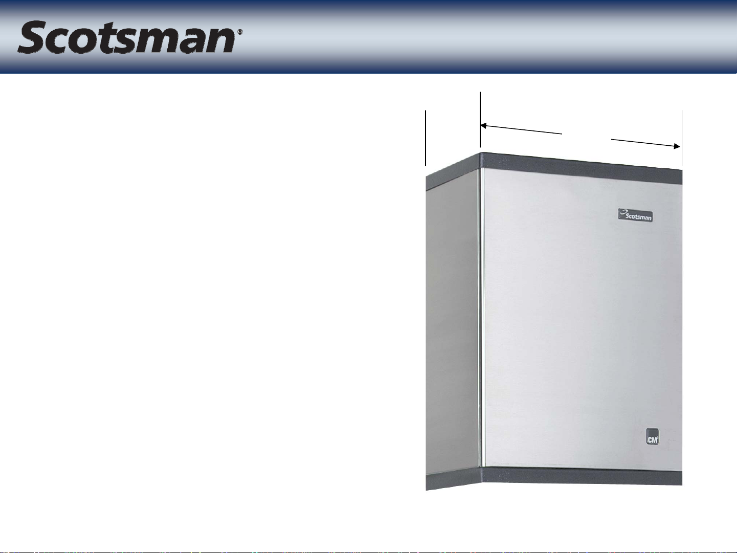
Ice Making Section
Ice Making Section
• CME686 or CME810
– Remote Low Side
• 22” wide by 16.5” deep
– Three evaporators
–Three TXVs
– Three check valves
–CM3technology
• Water and Control
Systems
16.5 22”
• Rotomolded freezing
compartment
• Refrigerant
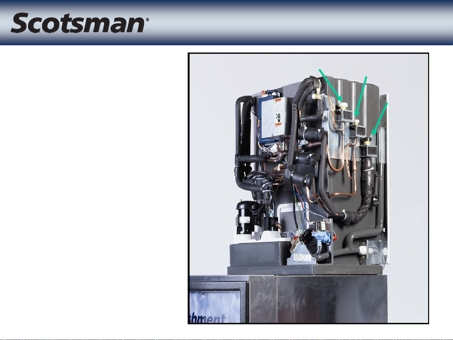
Ice Making Section
Ice Making Section
Vapor
Liquid
Line
Connections
– Vapor
– Liquid
–Suction
• All on right
side
– Designed for
Drive-Up
Suction
Window
Applications
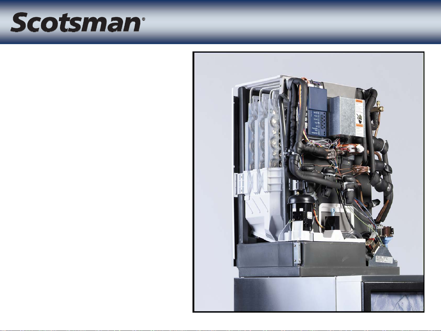
• Ice making
compartment
• Three
evaporators
– Circuited in
parallel
– No braze joints in
Ice Making Section
Ice Making Section
freezing
compartment
– Access from the
left side or top
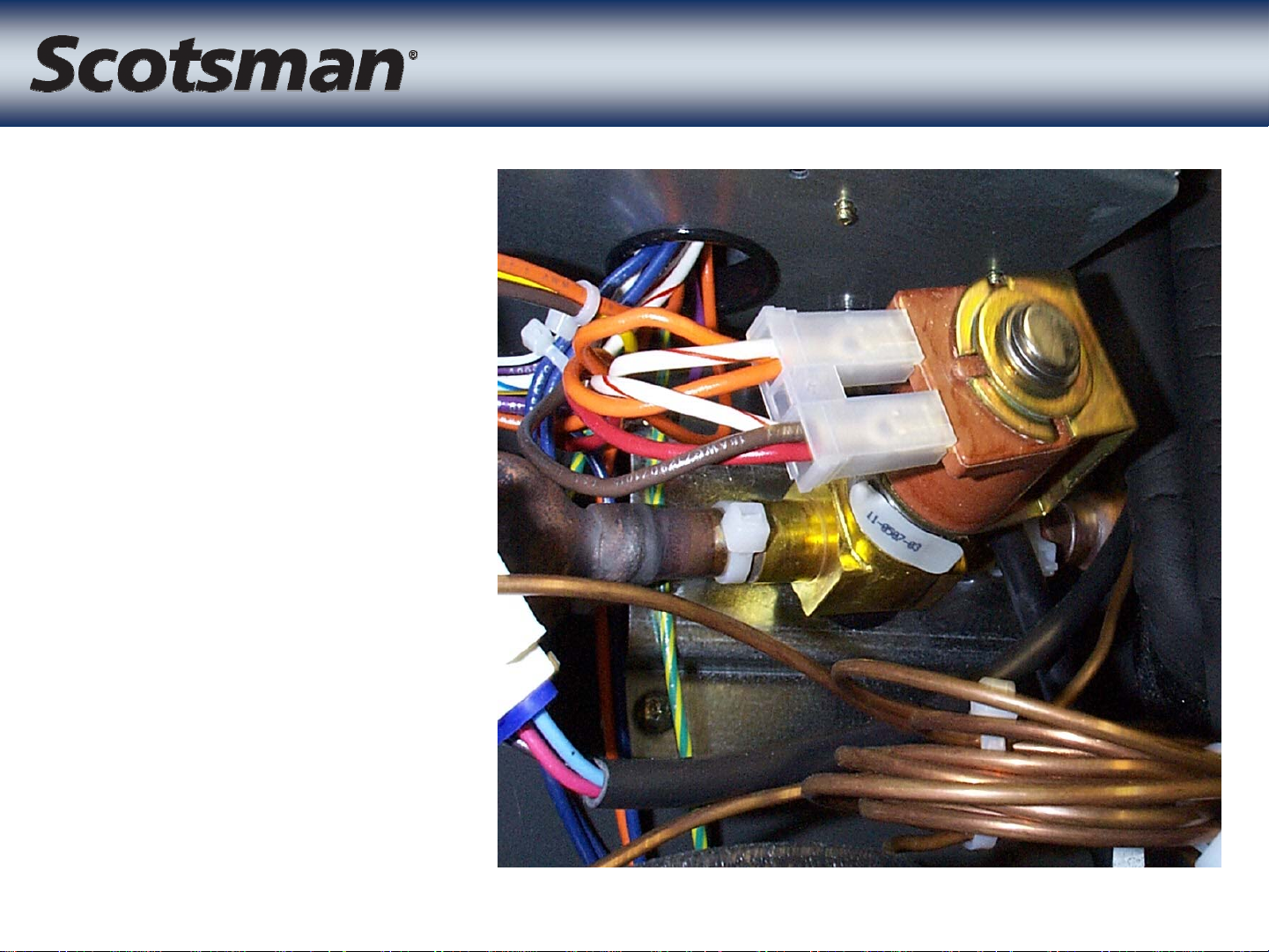
• Purpose: Opens
during harvest
to allow vapor
to enter the
evaporators
• 24 volt coil
Vapor Inlet Valve
Vapor Inlet Valve
• Different port
size between
CME686 and
CME810
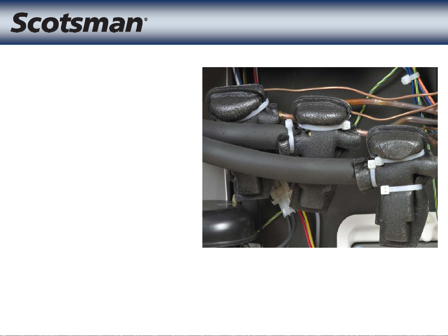
• Three internally
equalized valves
• Purpose: Control
individual
evaporator
superheats
– One valve per plate
Three
Three
TXVs
TXVs
– Promotes even
plate-to-plate ice
distribution
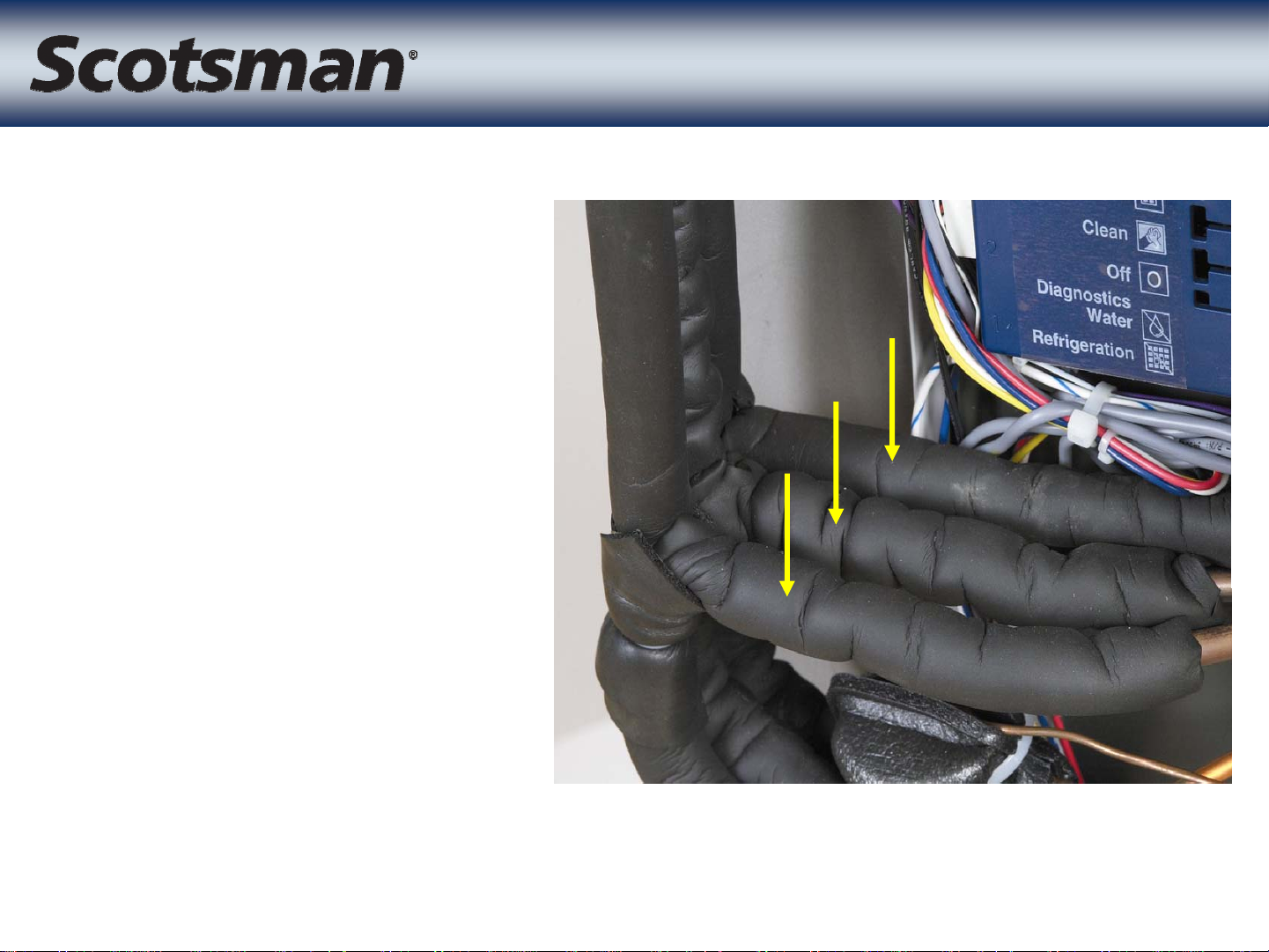
• Check valves
keep each TXV’s
refrigeration flow
directed to a
single evaporator
– Eliminates cross-
flow during freeze
Three Check Valves
Three Check Valves
cycle
– Each TXV outlet
must flow to one
evaporator
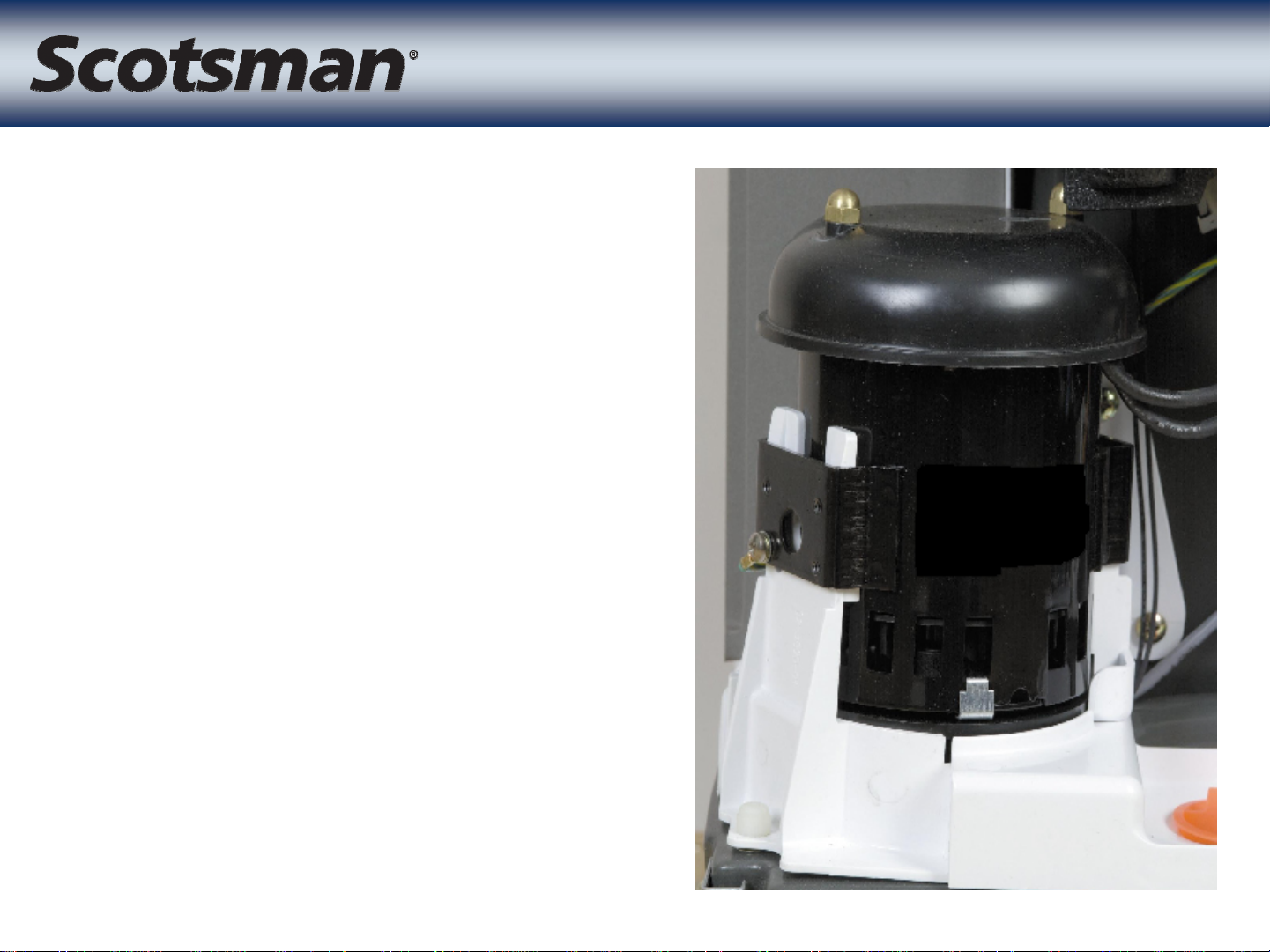
• 115 volt pump
• Same for both
CME686 and CME810
• Pedestal type
• Pump motor separated
from reservoir
Water Pump
Water Pump
– Keeps motor drier
– Motor cap keeps
condensation off motor
™
• AutoIQplus
• Uses sensors for
– ice harvest,
– bin full indications
– water reservoir
temperature
– water level
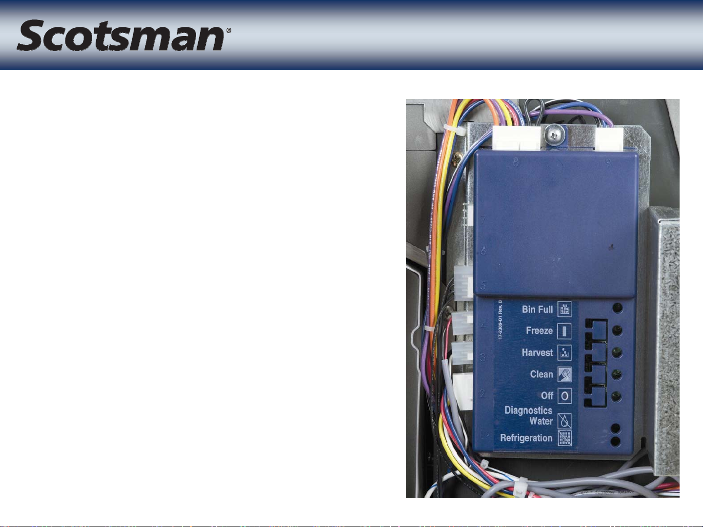
Controller
Controller
• Controls freeze and
harvest cycles
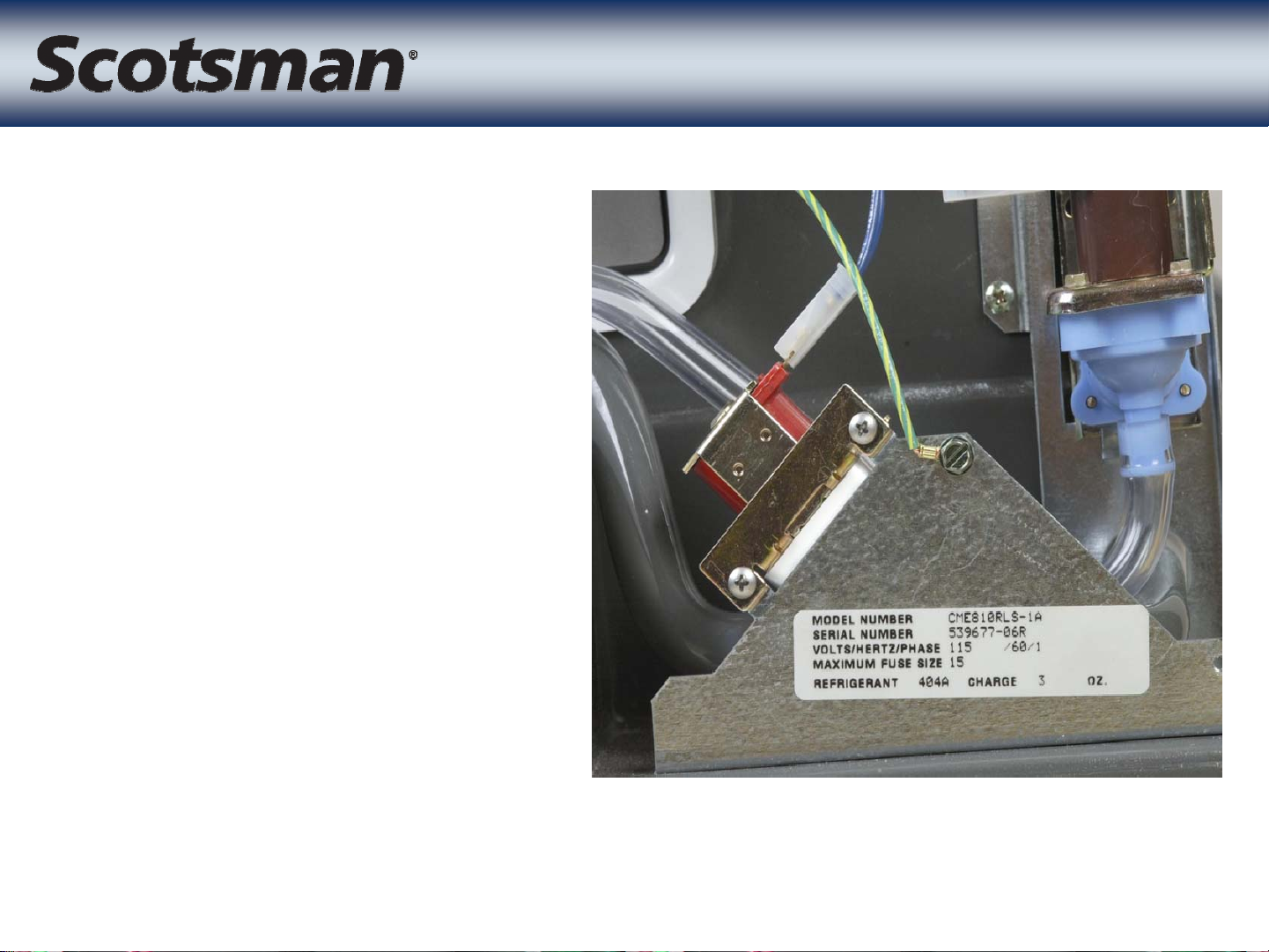
CME Electrical Box
CME Electrical Box
• Transformer 115 to 24, 85 VA
• Purge valve timer
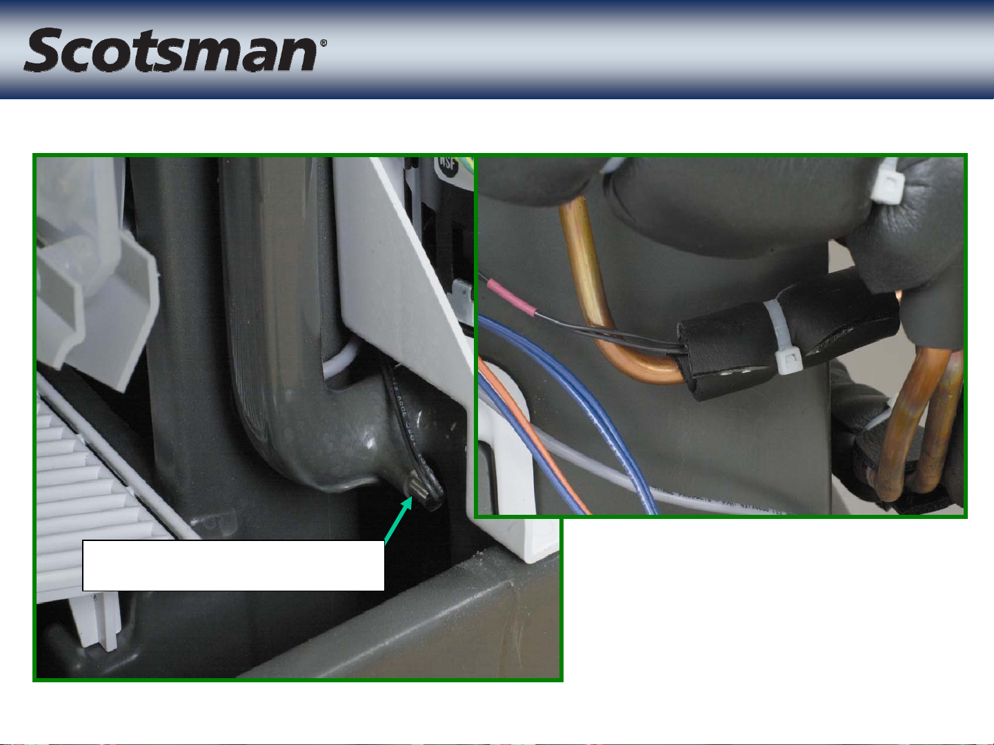
• Control wire connection
nearby
– Wire routes to compressor
package
– Controls contactor and solenoid
valves
Control Wire Connection
• Provides access
when left and right
side access is
limited
• Access to:
– cascading shield
– water trough
Inspection Cover
Inspection Cover
– ice sensors
• Also covers
cascading shield
fastener
• Removal
begins with
removal of the
inspection
cover
• Then remove
the one
Cascading Shield
Cascading Shield
retaining
screw
Cascading
Shield
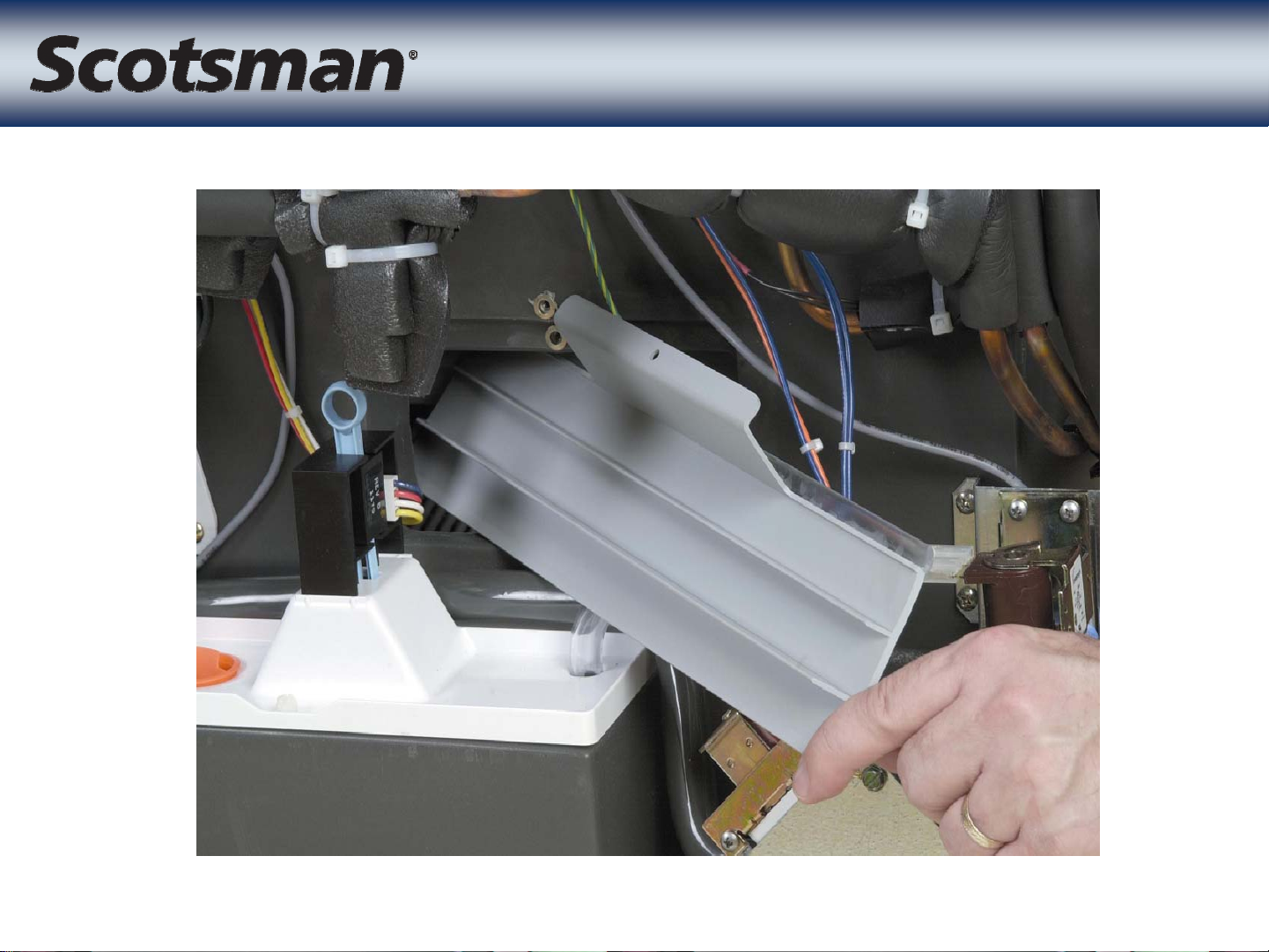
Cascading Shield
Cascading Shield
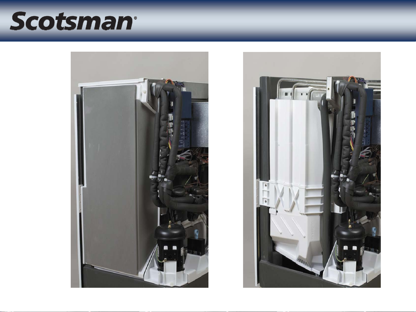
Evaporator Covers
Evaporator Covers

Freezing Compartment
Freezing Compartment
Water Trough
Cascading Shield
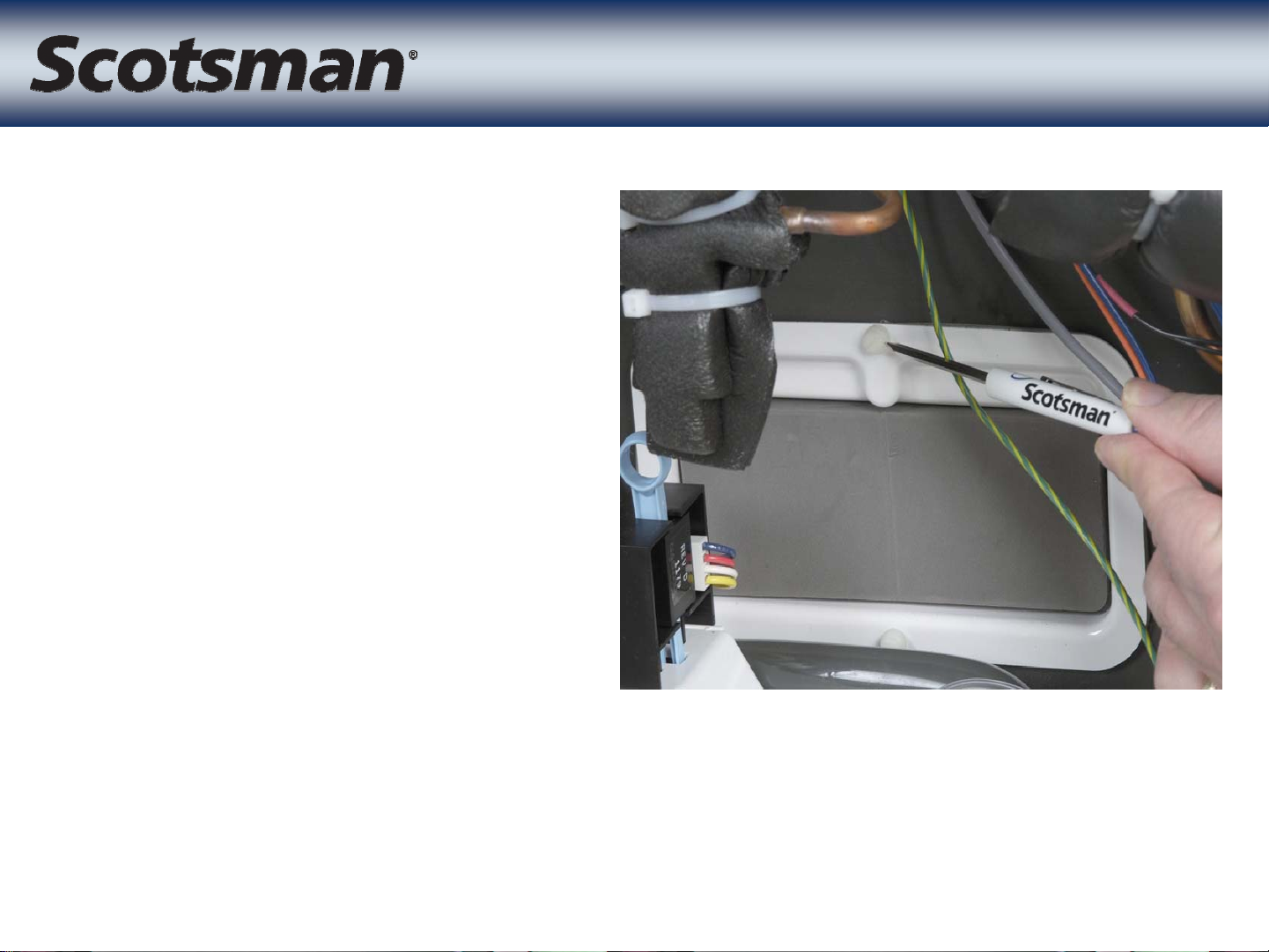
Temperature Sensors
Temperature Sensors
Liquid Line
Water Temp Sensor
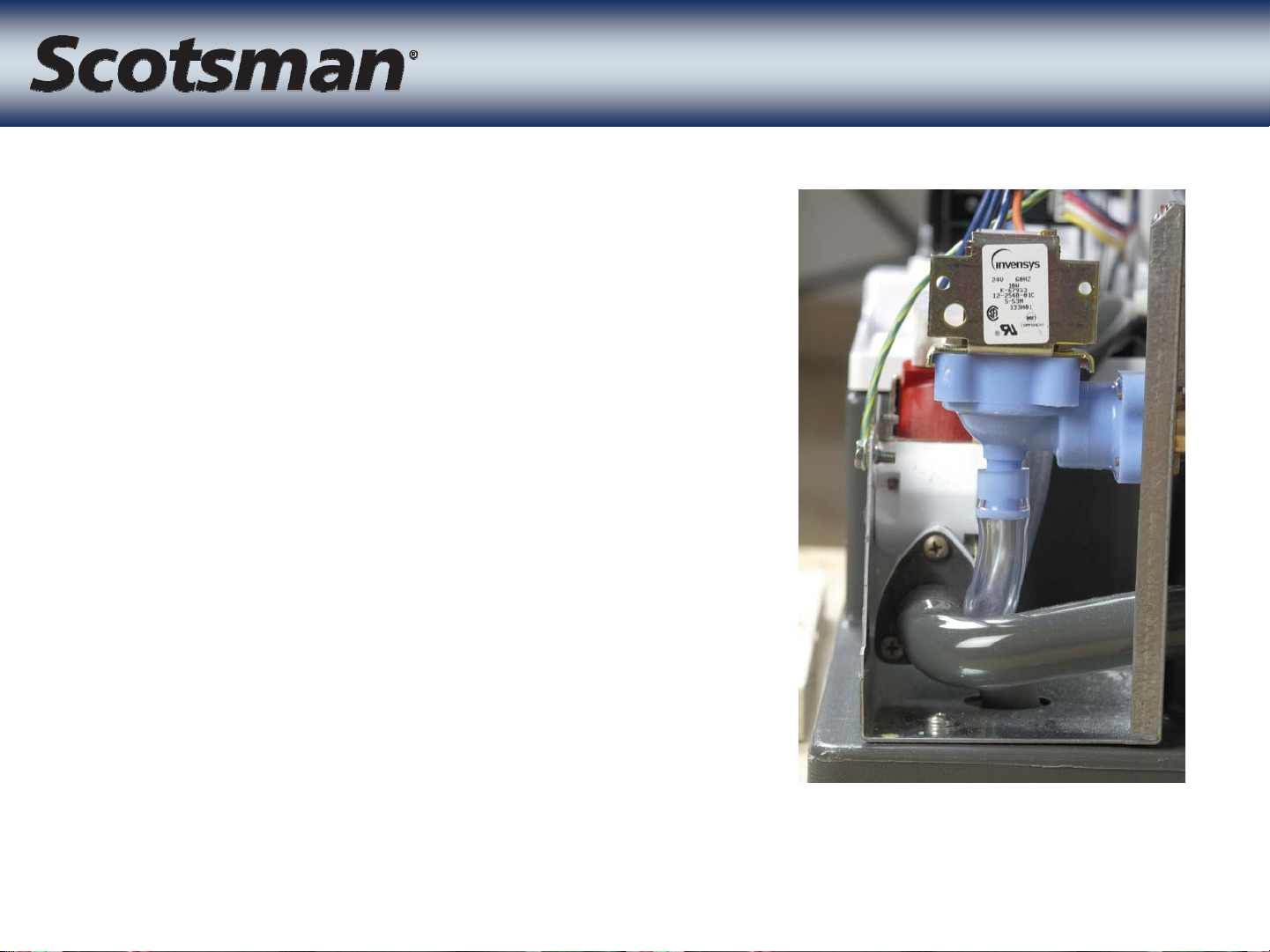
Inlet Water Valve
Inlet Water Valve
• Located in right front corner
of unit
• 1.25 GPM valve
– Same one as on CME256,
CME506 and many others
• Opens to add water and fill
reservoir
– Adds water during harvest
– Fills at beginning of freeze
– Refills once more during
freeze
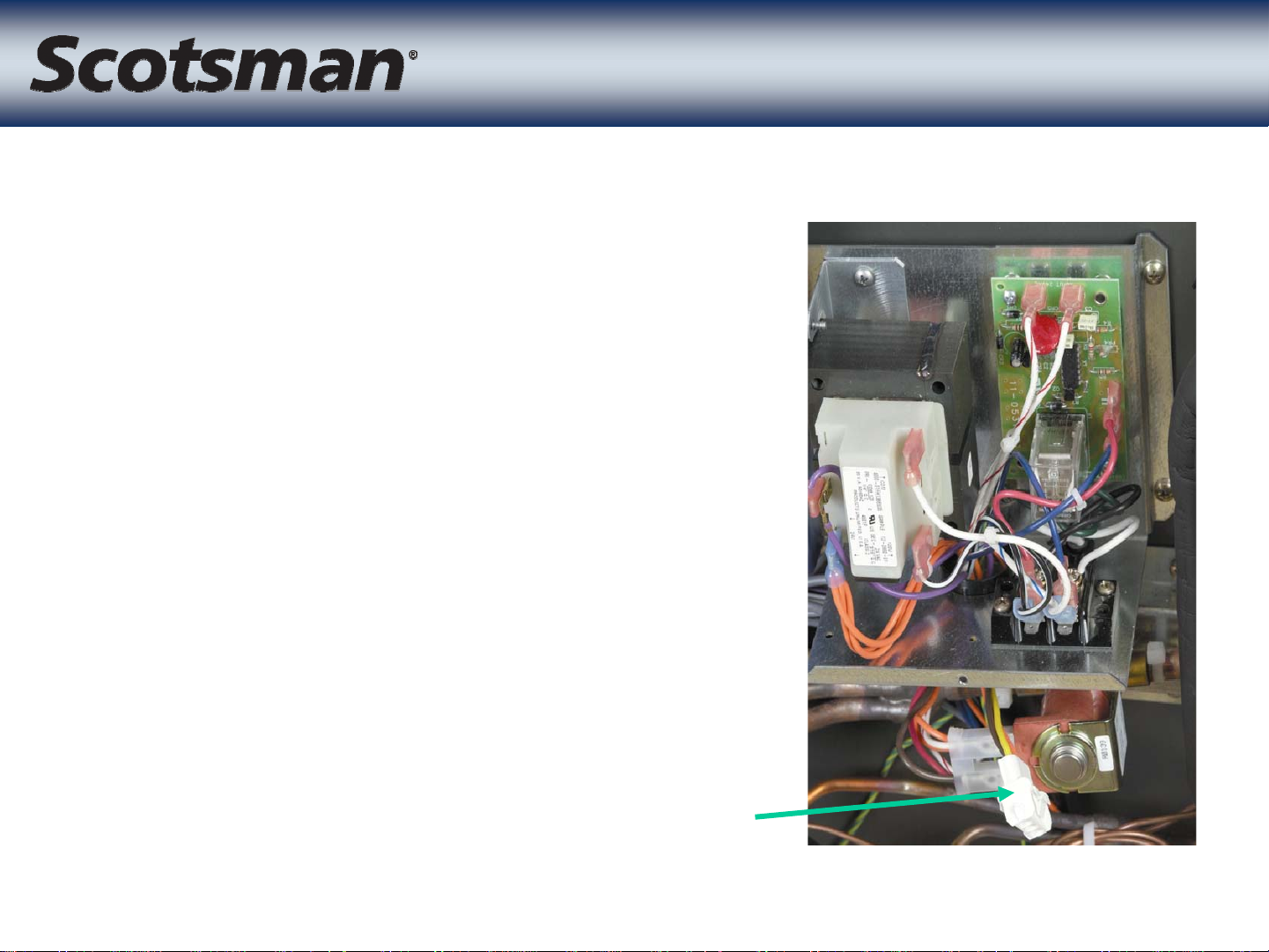
• Located in the front
of the unit
• 115 volt coil
• Opens to drain the
reservoir during
harvest
Purge Valve
Purge Valve
• Controlled by purge
valve timer
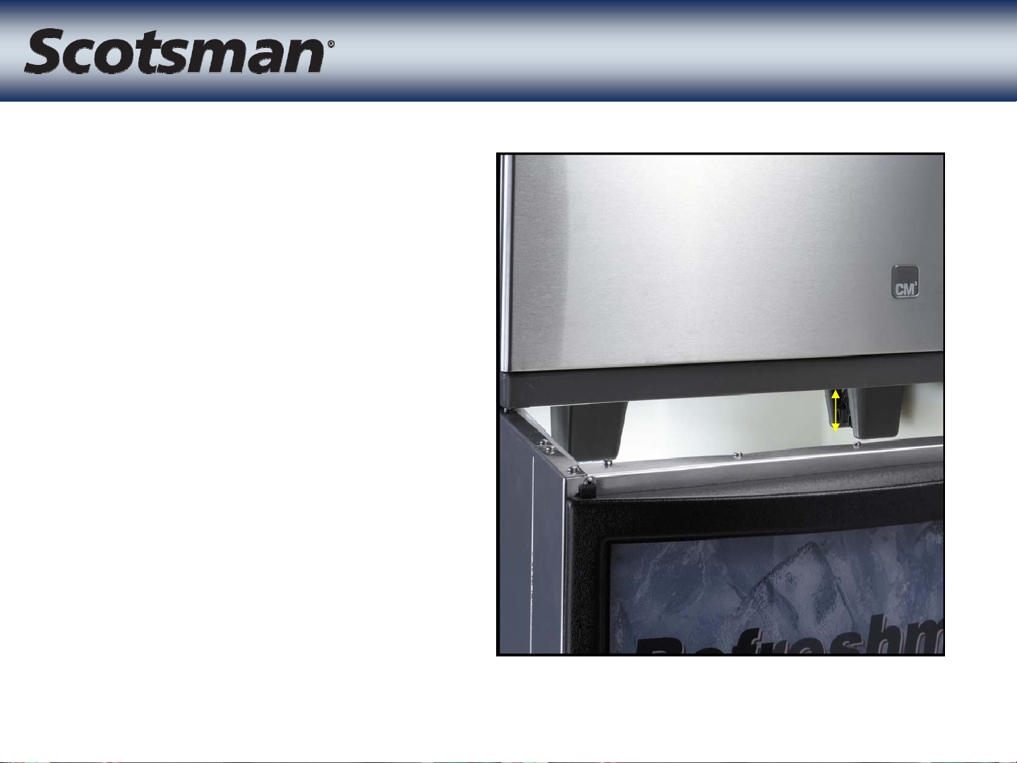
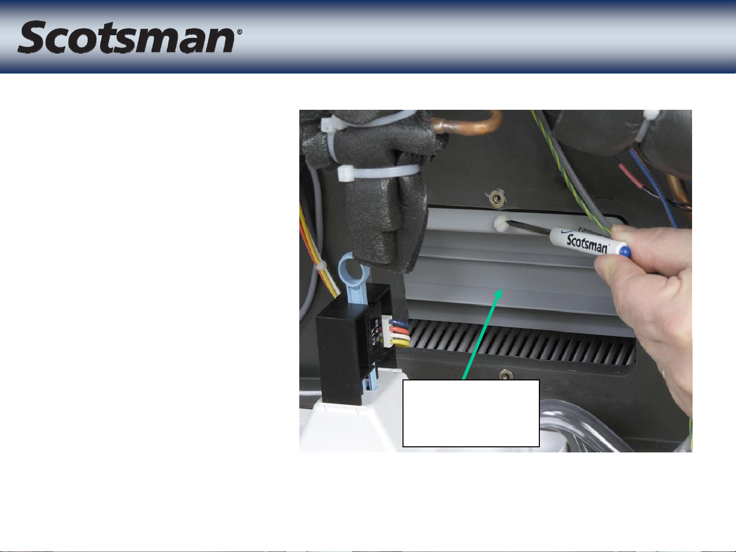
• Sensing position 3”
below base
• Control position
designed for
dispenser
Ice Sensors
Ice Sensors
applications
– Also works well on
bins
• Maximizes fill
without overfilling
3”
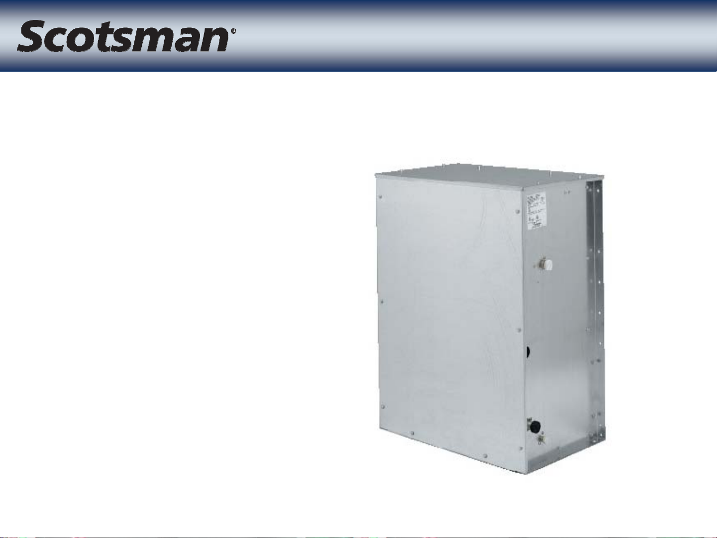
• Three models
–CP686
–CP886
– CP1086
Compressor Package
Compressor Package
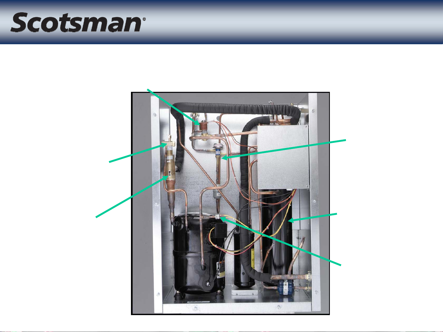
Condenser Bypass Valve
Low Side
Access Valve
CP Unit
CP Unit
Headmaster
CPR Valve
Receiver
High
Pressure Cut
Out - Auto
Reset

Crankcase Pressure Regulato
r
Crankcase Pressure Regulato
• CPR valve restricts
compressor dome
pressure during
harvest
– 55 to 60 PSIG
– Pre-set - don’t adjust
it!
• Low Side Access
valve has evaporator
pressure during
freeze, but not during
harvest
 Loading...