

Scotsman Eclipse Series, Eclipse 1600, Eclipse 2000, Eclipse 1300 Technical Training Manual
Page 1
30 Inch Wide Eclipse
Modular Cubers
Technical Training
Technical Training
Page 2
Eclipse 1300 --
Eclipse 1300
• Ice Making Head
– CME1386
– CME1686
• Compressor Package
– CP1316
– CP2086
2000
2000
• Condenser
– ERC1086
– ERC2086
Page 3

The Eclipse System
The Eclipse System
• The remote system is made up of three parts:
– Ice Making Section or Head Unit - 115 volt
– Compressor Package - 208-230 volt
– AC Condenser - 208-230 volt
• Flexible Modular System
– CME1386 or CME1686 can connect to CP1316
– ERC1086 can be used on 1000, 1300 or 1600 systems
– All are R-404A systems
Page 4
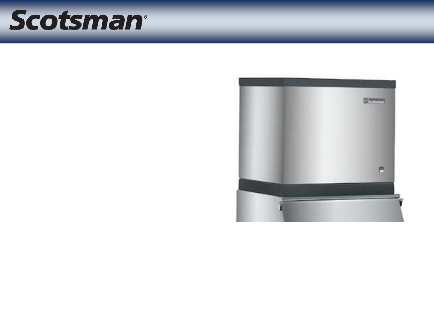
Ice Making Section
Ice Making Section
• 30” Wide Head Units
• CME1386 or
CME1686 or
CME2086
– Remote Low Side
–CM3technology
• Water and Control
Systems
• Rotomolded freezing
compartment
Page 5
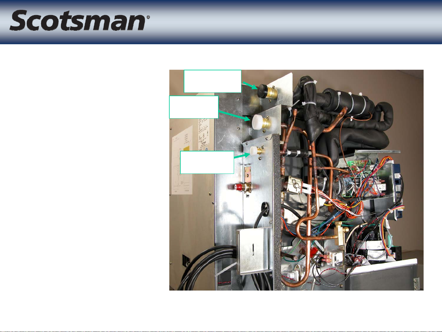
• Refrigerant
Line
Connections
– Vapor
Ice Making Section
Ice Making Section
Suction
Vapor
– Liquid
–Suction
Liquid
Page 6

• Ice making
compartment
• Five or Six
evaporators
– CME1386 has 5
– CME1686 and
CME2086 have 6
Ice Making Section
Ice Making Section
Page 7
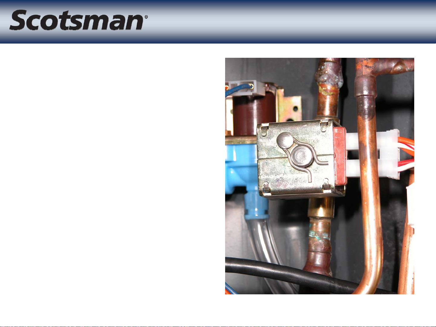
• Purpose: Opens
during harvest to
allow vapor to enter
the evaporators
• 24 volt coil
Vapor Inlet Valve
Vapor Inlet Valve
Page 8
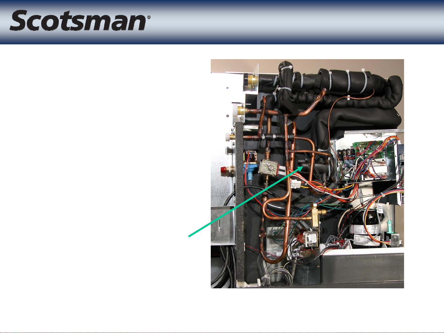
• Single externally
equalized valve
– Meters refrigerant
through a
distributor
One TXV
One TXV
TXV
Page 9
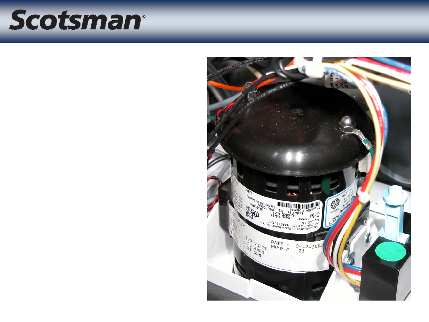
• 115 volt pump
• Same for all three
• Pedestal type
• Pump motor
separated from
reservoir
Water Pump
Water Pump
– Keeps motor drier
– Motor cap keeps
condensation off
motor
Page 10
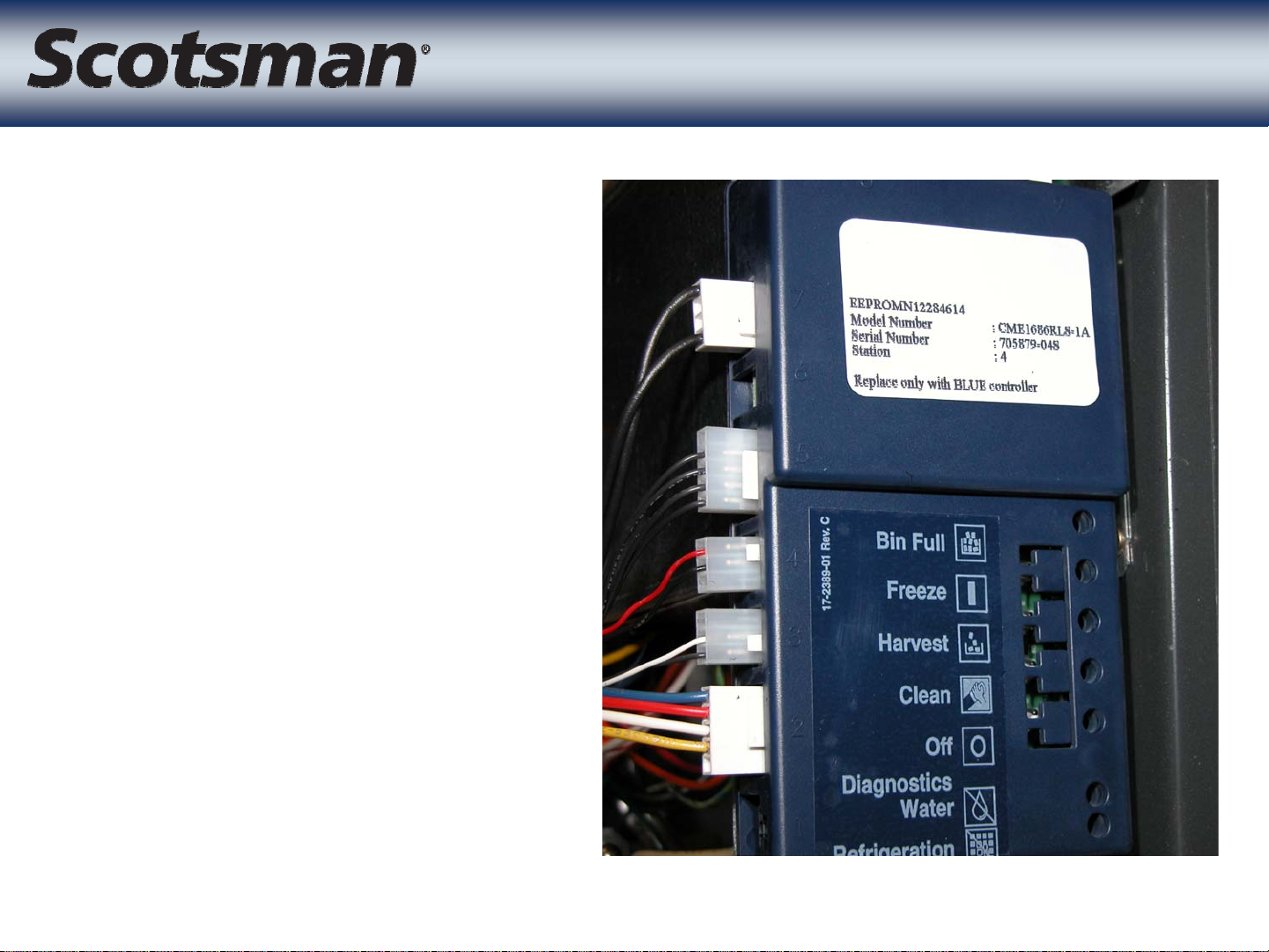
™
• AutoIQplus
• Uses sensors for
– ice harvest,
– bin full indications
– water reservoir
temperature
– water level
Controller
Controller
• Controls freeze and
harvest cycles
Page 11
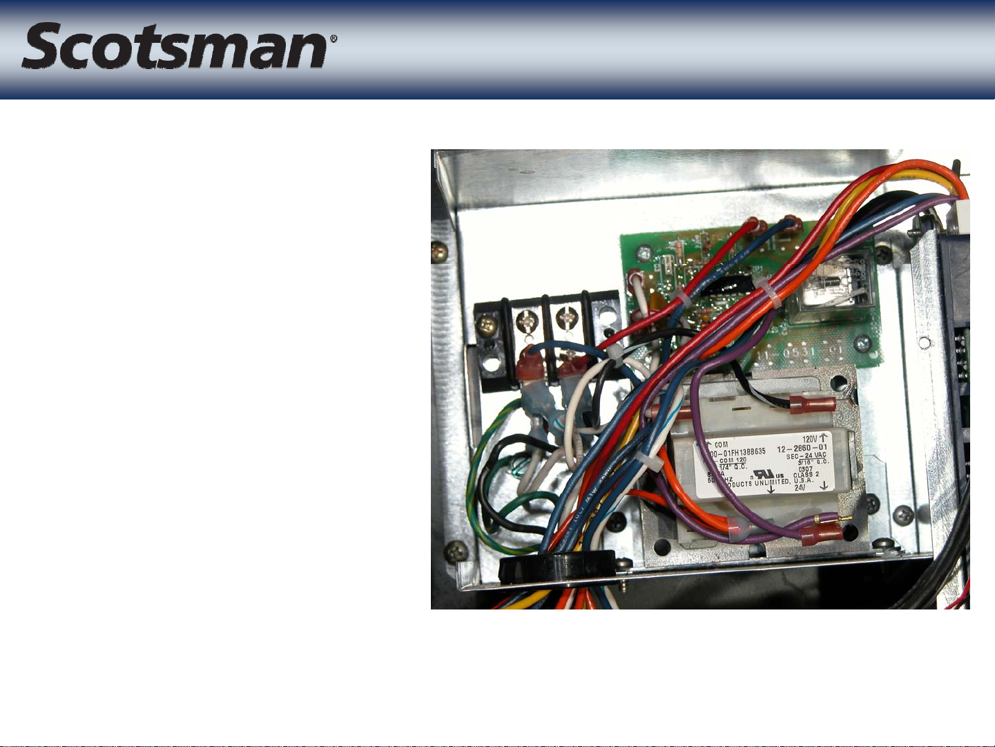
• Transformer 115
to 24, 85 VA
• Purge valve timer
• Control wire
connection
nearby
CME Electrical Box
CME Electrical Box
– Wire routes to
compressor
package
– Controls
contactor and
solenoid valves
Box purposely mounted at an angle
Page 12
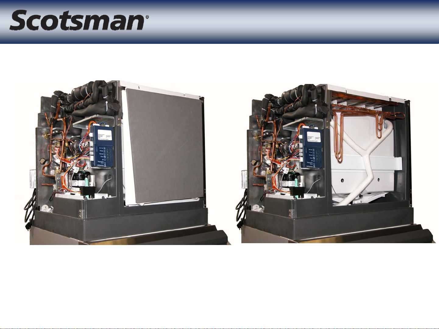
Evaporator Covers
Evaporator Covers
Page 13
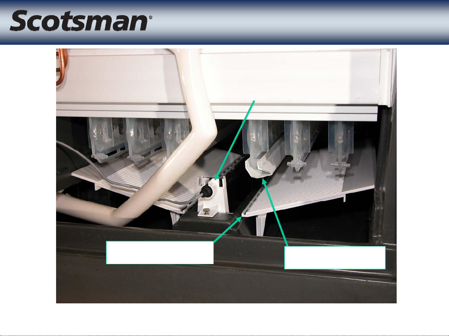
Freezing Compartment
Freezing Compartment
Front Ice Sensor
Cube Deflector
Water Trough
Page 14
• Two sensors
– Water
• In pump discharge hose
• Used to check water temp for anti-slush and
refrigeration system operation
– Liquid
Temperature Sensors
Temperature Sensors
• Used to determine which pre-set time for first harvest
cycle
– Lower temperatures = longer first harvest cycle
Liquid Line
Page 15
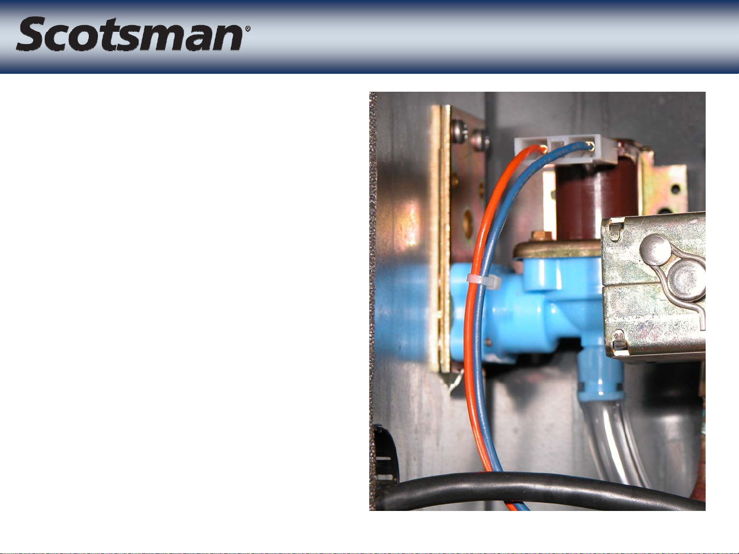
• Opens to add water
and fill reservoir
– Adds water during
harvest
– Fills at beginning of
freeze
– Refills once more
Inlet Water Valve
Inlet Water Valve
during freeze
Page 16
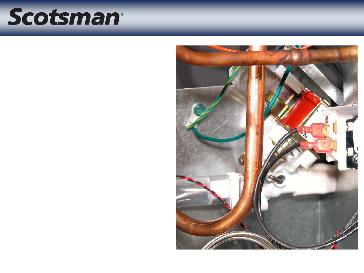
• Opens to drain the
reservoir during
harvest
• Controlled by purge
valve timer
Purge Valve
Purge Valve
Page 17
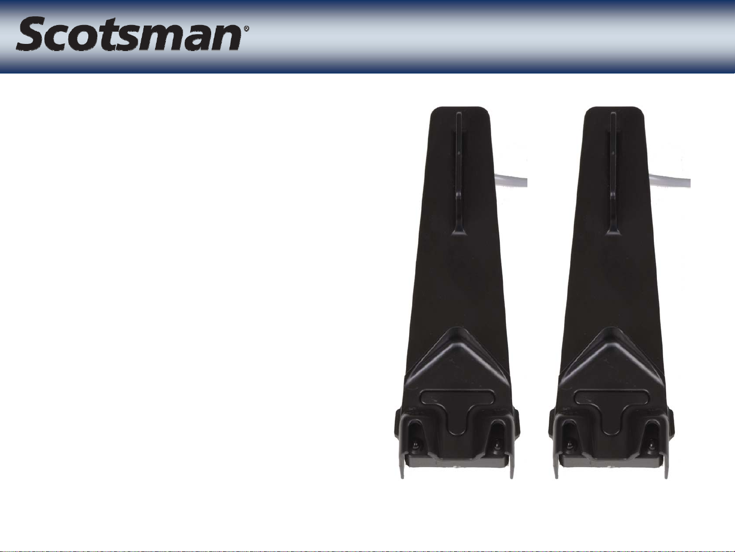
• Infrared sensors
– Located at the ice
outlet port
– Create a light curtain
– Harvesting ice triggers
the sensor
Ice Sensors
Ice Sensors
Page 18
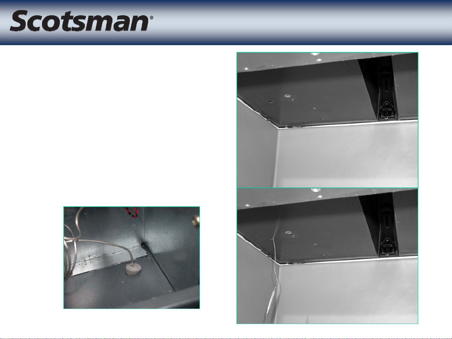
• CME1386, CME1686
and CME2086 are all
equipped with a bin
thermostat.
• Thermostat routes
through hole in base.
Bin Thermostat
Bin Thermostat
Page 19
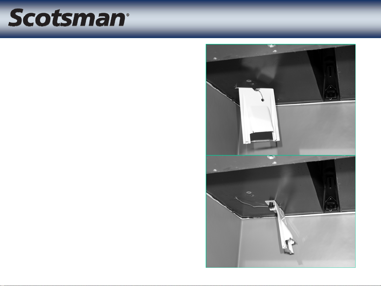
• Thermostat bulb must
be mounted to the
bracket
• The bracket mounts
to the bottom of the
ice machine
Bin Thermostat
Bin Thermostat
Page 20
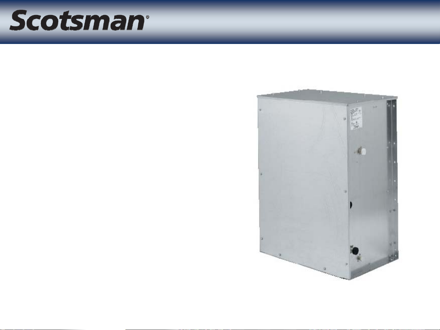
• Two models
– CP1316
• Reciprocating compressor
– CP2086
• Scroll compressor
Compressor Package
Compressor Package
Page 21
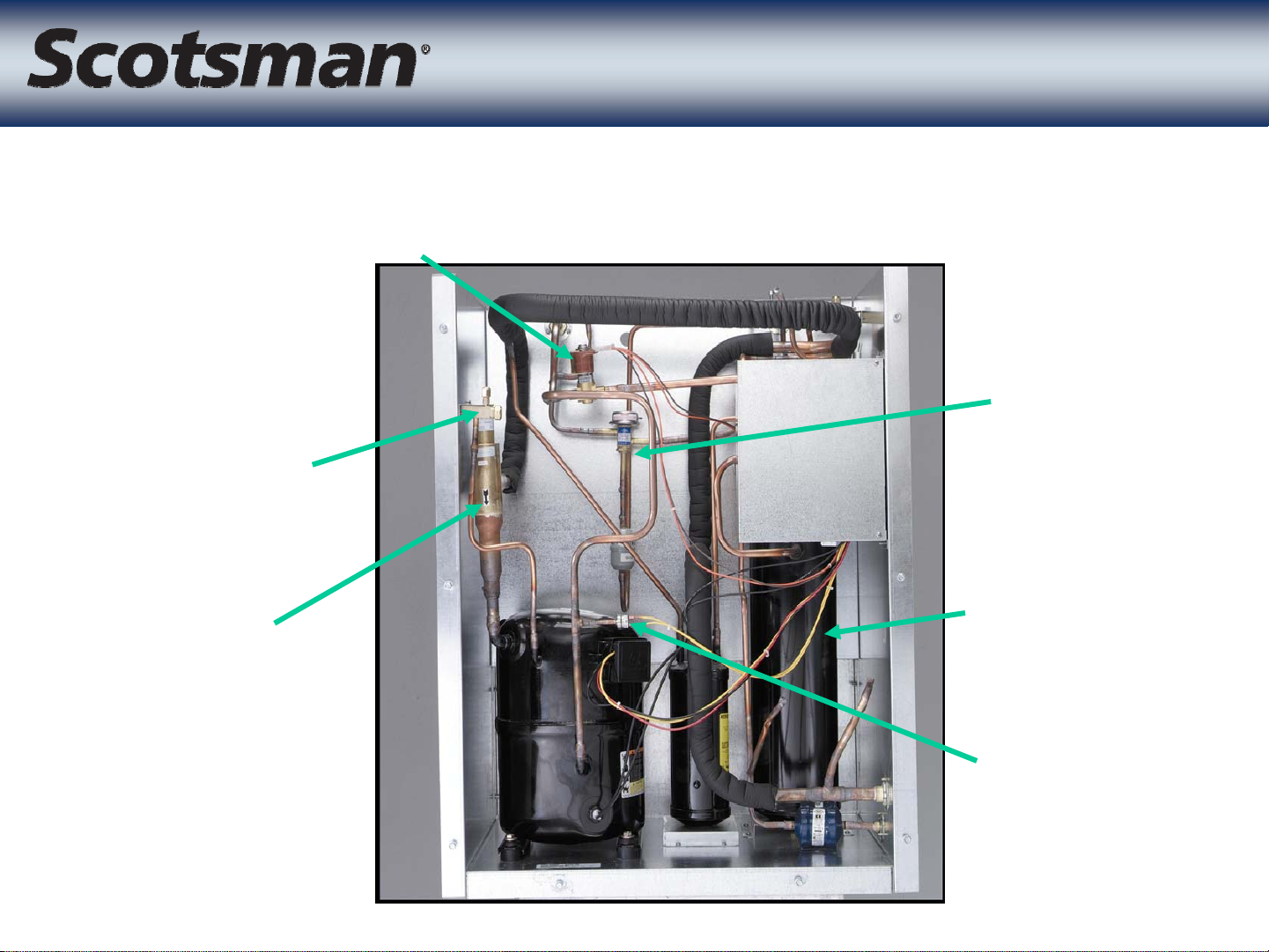
Condenser Bypass Valve
Low Side
Access Valve
CP Unit
CP Unit
Headmaster
CPR Valve
Receiver
High
Pressure Cut
Out - Auto
Reset
Page 22

Access Valves
Access Valves
Low Side: Compressor Suction
High Side: Compressor Discharge
Receiver Liquid Outlet
Page 23
Crankcase Pressure Regulator
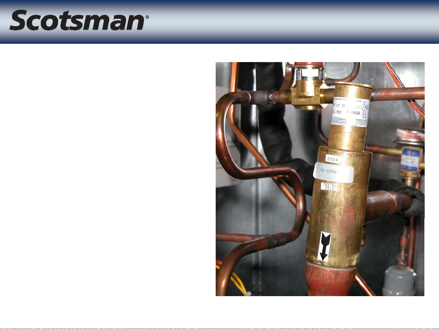
Crankcase Pressure Regulator
• CPR valve restricts
compressor dome
pressure during
harvest
– 55 to 60 PSIG
– Pre-set - don’t adjust
it!
Page 24

Condenser Bypass Valve
Condenser Bypass Valve
• Normally Closed, opens during harvest
• Bypasses condenser coil and directs discharge
gas to vapor line
Page 25

• Maintains discharge
pressure during
freeze
• Active at any temp
o
below 70
– Rated at 217 PSIG,
freeze cycle pressure
F.
Headmaster
Headmaster
may be between 220
and 250 during cold
ambient operation
Page 26

Liquid Inlet Valve
Liquid Inlet Valve
• Normally Open, closes
during harvest
• Controls liquid flow
into receiver
• Isolates refrigerant in
condenser during
harvest
• Improves cycle time
Page 27

Receiver
Receiver
• Shipped with system charge
• Three ports
– Liquid inlet
– Liquid outlet
– Vapor outlet
Liquid Out
Liquid In
Vapor Out
Page 28

• Toggle switch controls
condensing unit
• Control Wire
connection from Ice
Making Section to
control the system
Electrical Box
Electrical Box
Toggle Switch
• Electrical power
connected at contactor
• Remote condenser fan
connects at contactor
Control Wire Connection
Page 29

• Scroll compressor
• Three Phase
– Supply wiring can make it
start backwards
– To fix, switch two power leads
• Single Phase
CP2086
CP2086
– Always starts with the correct
rotation
– Can reverse after power
interruption
– Time delay relay in circuit to
prevent reversal
Page 30

CP2086 Single Phase
CP2086 Single Phase
• Compressor protection
circuit
– 24 volt transformer
– 24 volt relay
– Time Delay Relay
• Power interruption of as
little as 15 milliseconds
Transformer
causes relay to shut
compressor off for 30
seconds
• Compressor then
restarts
Relay
Time Delay Relay
Page 31

• Oil sight glass and
oil drain / fill port
• Don’t add oil!
– Oil level will
change during
each cycle
– Ranges between
Scroll Compressor
Scroll Compressor
1/3 & 1/2 full
Page 32

Condensers
Condensers
• Two models - ONLY for Eclipse
– ERC1086 - used with CP1386 and CP1686
– ERC2086 - only used with CP2086
• No headmaster in condenser
– Headmaster is in CP unit
• Swivel nut connections for CP unit
– Don’t connect these condensers to a regular remote!
Page 33

• Three systems,
single and three
phase for each
– 1300
– 1600
– 2000
• Must match
System Installation
System Installation
components to
create system
Page 34

• 1300 -
– CME1386, CP1316, ERC1086
• 1600 -
– CME1686, CP1316, ERC1086
• 2000 -
– CME2086, CP2086, ERC2086
System Installation
System Installation
• CP units may also be connected to approved
central condenser coil using tubing kit RTE10
– Coil must NOT have headmaster
Page 35

Equipment Location
Equipment Location
• CME can be above or below
condensing unit
– If above, limit is 15 feet
• Pre-charged lines are used
– 3 tubes per set
– 20, 50 and 75 foot only
– No extra refrigerant charge required
– S trap required when condensing
unit is over 20’ above ice making
head
Page 36

Other Configurations
Other Configurations
Approved Central Condenser Coil
CP Unit
RTE10 Line Set
Ice Making Head
3RTE Line Set
Page 37

Condensing Unit
Condensing Unit
• Modular system - connect
CP to ERC
• Assemble on roof or ground
• ERC has back legs and two
braces
– Assemble legs and braces to
condenser
• Connect wires to junction
box
• Place ERC on back of CP -
lip on CP holds ERC up
Page 38

• Fasten CP to ERC
• Connect liquid and
discharge line
connections
• Route wire to CP
control box and
Condensing Unit
Condensing Unit
connect to contactor
Page 39

Quick Connects
Quick Connects
Partial Assembly, One Thread Showing
Status: Not Ready, diaphragms partially pierced
Page 40

Quick Connects
Quick Connects
Partial Assembly, Threads are Flush
Status: Not Ready, diaphragms pierced but connection not leak
proof.
Page 41

Quick Connects
Quick Connects
Completed Assembly
Status: Ready, diaphragms fully pierced and joint is leak proof
Page 42

• Three tubes
• Reversible
• CME routing
determines which end
goes to CME
– Out the back - use
Line Set
Line Set
double-bend ends at
CME
– Out the top - use single
90 degree ends at CME
Ends for out the
CME top
Ends for
out the
CME
back
Page 43

Line Set Installation
Line Set Installation
• Route lines in two groups
– Liquid and Vapor
– Suction separately for ease of routing
• 3/4” tube requires careful handling
– Check for holding charge before installation
– Route control wire with line set
– Only shorten if necessary
• Do before connections are made!
• Purge with nitrogen while brazing
– Schraders at both ends for purging
• Evacuate to 300 microns or less
• Add holding charge if connecting later
Page 44

• Flush against wall
capability
• Drains left or back
Install CME
Install CME
Vent Tube
• Route refrigeration
tubes out the top for
flush installations
• 115 volt unit, cord
provided
Drain Fitting
Page 45

• Attach water inlet
• Attach drain - 3/4”
• Connect refrigerant
tubing. Add foam
tape/cork tape to
suction line nut
Utility Connections
Utility Connections
• Secure unit at sides
or back with
provided strap-clips
Page 46

• Connect precharged
lines
– Use refrigerant oil
– Use two wrenches to
prevent quickconnect diaphragm
damage from rotating
Condensing Unit
Condensing Unit
tube
• Connect control wire
• Connect power,
check voltage
Page 47

• Check installation
– Power
– Water
–Drain
– Tube Routing
• No soak out needed
Initial Start Up
Initial Start Up
– Plug in CME unit
– Check EEPROM code
– Push Freeze to start
Page 48

• CME unit
– Opens & closes Purge Valve
– Fills with water
– Switches on Pump
– Switches on Condensing Unit
• Compressor and fan begin to operate
Start Up
Start Up
• Adjustments
– Purge is adjustable
Page 49

Operation --
Operation
• CM3control system
– Water level sensor for
• Reservoir water fill
• Freeze cycle termination
– Ice sensors to sense
• Ice harvest
– Controller determines cycles and operates
Control System
Control System
components
• Uses water level to determine freeze cycle length
• Uses length of time for ice to fall to determine next
harvest
• Uses thermostat to determine bin full
Page 50

• Water level sensor
– Two photo-electric eyes
in housing
– Top eye blocked tells
controller water level is
low
– Bottom eye blocked
Control Details
Control Details
tells controller water
reservoir is full
Page 51

Control Details
Control Details
• Ice sensors - photo-
eyes
– Located at bottom of
ice drop zone
– One side is an emitter,
the other a detector
– Creates a light curtain
that can sense groups
of cubes falling during
harvest
Page 52

Operation --
Operation
Freeze
Freeze
• Similar to conventional remote ice cubers
– Condensing unit forces liquid refrigerant to the ice
making section
• TXV meters refrigerant all evaporators
– At a pre-determined water temperature, the pump
stops for 30 seconds
– As ice forms on the evaporators, the water level drops
– About half way through the cycle the water reservoir
re-fills
– The next time the water level drops to the point where
the top of the slot in the float stick blocks the eyes, the
system goes into the harvest cycle
Page 53

Operation --
Operation
Harvest
Harvest
• Eclipse features Cold Temperature Harvest
– Condensing Unit may be located outside
• Temperature Range between -20 and 120 F.
• Receiver is with the condensing unit
• Vapor line connects discharge gas and receiver vapor to
vapor inlet line in ice making section
• High vapor flow rates achieved with no compressor
impact due to use of CPR valve
• Vapor contains latent heat - even at sub-zero
temperatures
• Condensing vapor in the evaporators transfers the heat
• Evaporators warm up and ice is released
Page 54

Operation --
Operation
• Vapor inlet valve opens
• Condenser bypass valve opens
• Receiver inlet valve closes
• Purge valve opens
• Pump stops for a time then restarts to purge the
reservoir of water
Harvest Details
Harvest Details
• Purge valve closes after 40 seconds
• Inlet water valve opens for a few seconds to add
water to the reservoir for harvest assist
• Harvest continues until the controller stops it
Page 55

Operation --
Operation
• Controller begins timing harvest
• Ice falling interrupts the signal from the ice sensor
emitter to the receiver
– The time of that interrupt is recorded by the controller
– The last time the controller receives an interrupt signal
is saved as the cube release time
Harvest Control
Harvest Control
– Extra time is calculated from the actual cube release
time
Measured Cube Release Time + Calculated Extra Time =
Harvest Time
Page 56

Operation
Operation
• Freeze Cycle Time (90/70):
– 1300 - 16 to 17 minutes
– 1600 - 17 to 18 minutes
– 2000 - 12 to 13 minutes
• Harvest Cycle Time (90/70)
– 1300 - 2 minutes
– 1600 - 1 1/2 to 2 minutes
– 2000 - 2 1/2 minutes
Page 57

Condensing Unit
Condensing Unit
Condenser Bypass Valve
Headmaster
Compressor
CPR
Liquid
Inlet
Valve
(N.O.)
Rec
.
Page 58

Ice Making Section
Ice Making Section
Vapor Inlet Valve
Distributor Tubes
Suction
Vapor Liquid
TXV
Distributor
Evaporators
Page 59

• Freeze Cycle
– Rapid Pull Down to
between 50 and 40
PSIG
– Gradual Pull Down to
• 1300 30 to 34 PSIG
• 1600 35 to 37 PSIG
System Pressures
System Pressures
• 2000 23 to 25 PSIG
just before Harvest
– Pressures at CP unit or
CME will be the same
during Freeze
2000 lb model, end of freeze
Page 60

• Harvest Cycle
– At the ice making
section, low side
pressure rapidly
increases to 90 - 95
PSIG or higher in hot
ambient conditions
System Pressures
System Pressures
– At the CP unit
compressor access
valve, dome pressure
is limited by the CPR
valve to 55 - 60 PSIG
during harvest
Page 61

• CP Unit
– Discharge during low
ambient freeze will be
about 240 PSIG
– Discharge during harvest
will be about 100 PSIG
– High Pressure Cut Out
System Pressures
System Pressures
opens at 450, closes at
350 PSIG
Page 62

Maintenance
Maintenance
• De-lime with Scotsman Ice Machine Cleaner
– Push & release clean button
– Pour in 24 ounces of ice machine cleaner
– Clean for 10 minutes, then push and release clean
button again, wait 20 minutes and shut unit off
• Check distributors for scale build up
Page 63

Service Diagnosis
Service Diagnosis
• What happens if?
• Vapor Inlet Valve Does
Not Open
– Vapor line hot
– Discharge pressure
increases
– Low side pressure does
not change
– No ice release - large
slabs of ice
– 2 blink refrigeration light
Page 64

Service Diagnosis
Service Diagnosis
• What happens if?
• Control wire becomes
unplugged
– CP unit does not
operate
– Exceeds maximum
freeze time
• Controller shows
continuous
refrigeration diagnostic
light
Page 65

• What happens if?
• Condenser by pass
valve does not open
– High pressure cut out
opens
• Note: High discharge
pressure during
Service Diagnosis
Service Diagnosis
harvest will not be
present at liquid
connection
– Ice may release, but
slowly
Page 66

• What happens if?
• Receiver inlet valve
does not close during
harvest
– Very little change
• If it sticks closed
Service Diagnosis
Service Diagnosis
– Hi discharge pressure
cut out opens
– Controller shows
continuous diagnostic
light
Page 67

Service Diagnosis
Service Diagnosis
• What happens if?
• Headmaster is stuck in
bypass
– Very little liquid flow to
TXVs
– Long freeze cycle
– Controller shows
continuous refrigeration
diagnostic light
Page 68

Service Diagnosis
Service Diagnosis
• What happens if?
• There is a refrigerant leak
– No change until refrigerant level drops below the
operational threshold for the ambient
• Headmaster will try to maintain minimum discharge
pressure - but will be hissing as gas flows through
• Ice formation will be poor
• Low capacity/long freeze cycle will result
– Add charge to confirm, if ice making resumes with
normal discharge pressure there is a leak
Page 69

Service Diagnosis
Service Diagnosis
• What happens if?
• There is no water to the ice making section
– Water is part of the recipe for ice!
– Controller will stop unit operation but retry filling every
20 minutes until water is restored
Page 70

• What happens if?
• The purge valve
leaks through
– May result in small
cubes
– Short freeze cycle
Service Diagnosis
Service Diagnosis
– May have long
harvest cycle
Page 71

• What happens if?
• The inlet water
valve leaks through
– Keeps adding water
(heat load) to
reservoir
Service Diagnosis
Service Diagnosis
– Result is a long
freeze cycle
Page 72

Service Diagnosis
Service Diagnosis
• What happens if?
• The condenser fan stops
– CP unit’s hi pressure cut out will open
– Maximum freeze time will be exceeded
– CME unit will shut system off
– Controller will display continuous refrigeration
diagnostic light
Page 73

• What happens if?
• The CPR valve fails
– Pressure during harvest will not be at the pre-set point
• 55 to 60 PSIG
– Will not hold an adjustment
– No external symptom
Service Diagnosis
Service Diagnosis
• CPR setting should be checked if compressor is
replaced
Page 74

Service Diagnosis
Service Diagnosis
• What happened if?
• The controller is showing a one blink refrigeration
diagnostic light
– This indicates that the ice harvest was very slow and
the controller timed-out on maximum harvest time
– Ice was sensed by the control system
– Likely causes include
• Beginning to freeze up
Page 75

Service Diagnosis
Service Diagnosis
• What happened if?
• The controller is showing a two blink refrigeration
diagnostic light
– This indicates that the ice harvest was very slow and
the controller timed-out on maximum harvest time
– Ice was NOT sensed by the control system
– Likely causes include
• Freeze up
• Vapor inlet valve did not open
• Ice sensor can’t “see” ice well
Page 76

Service Diagnosis
Service Diagnosis
• What happened if?
• The controller is showing a continuous
refrigeration diagnostic light
– Maximum freeze time exceeded
– Dirty condenser coil
– Fan motor inoperative
Page 77

Service Diagnosis
Service Diagnosis
• What happened if?
• The controller is showing a two blink water
diagnostic light
– Slow or no water fill
• Possible clogged water filters
– Low water level - leaks out
– Water level sensor not working or harness connection
poor
Page 78

Service Diagnosis
Service Diagnosis
• What happened if?
• The controller is showing both diagnostic lights
on continuously
– This indicates that the temperature sensors are not
working or not plugged in. They need to be plugged
back in or replaced.
– The ice machine will operate without the thermistors
working, but it is limited in its diagnostics that way
Page 79

Summary
Summary
• Eclipse is a three part ice making system
– Ice making head
– Compressor Package
– Condenser
• There are 6 systems
– 600
– 800
– 1000
– 1300
– 1600
– 2000
 Loading...