

Scotsman ECC Series Remote Condensing Unit, EH222 Prodigy Plus Eclipse 1000, EH222 Prodigy Plus Eclipse 800, EH330 Prodigy Plus Eclipse 1400, EH430 Prodigy Plus Eclipse 1400 Technical Guide
...Page 1
New Eclipse Technical Review
Models
ECC0800, ECC1200, ECC1410, ECC1800
EH222-C, EH330-C, EH430-C
Page 2

New Eclipse Technical Review
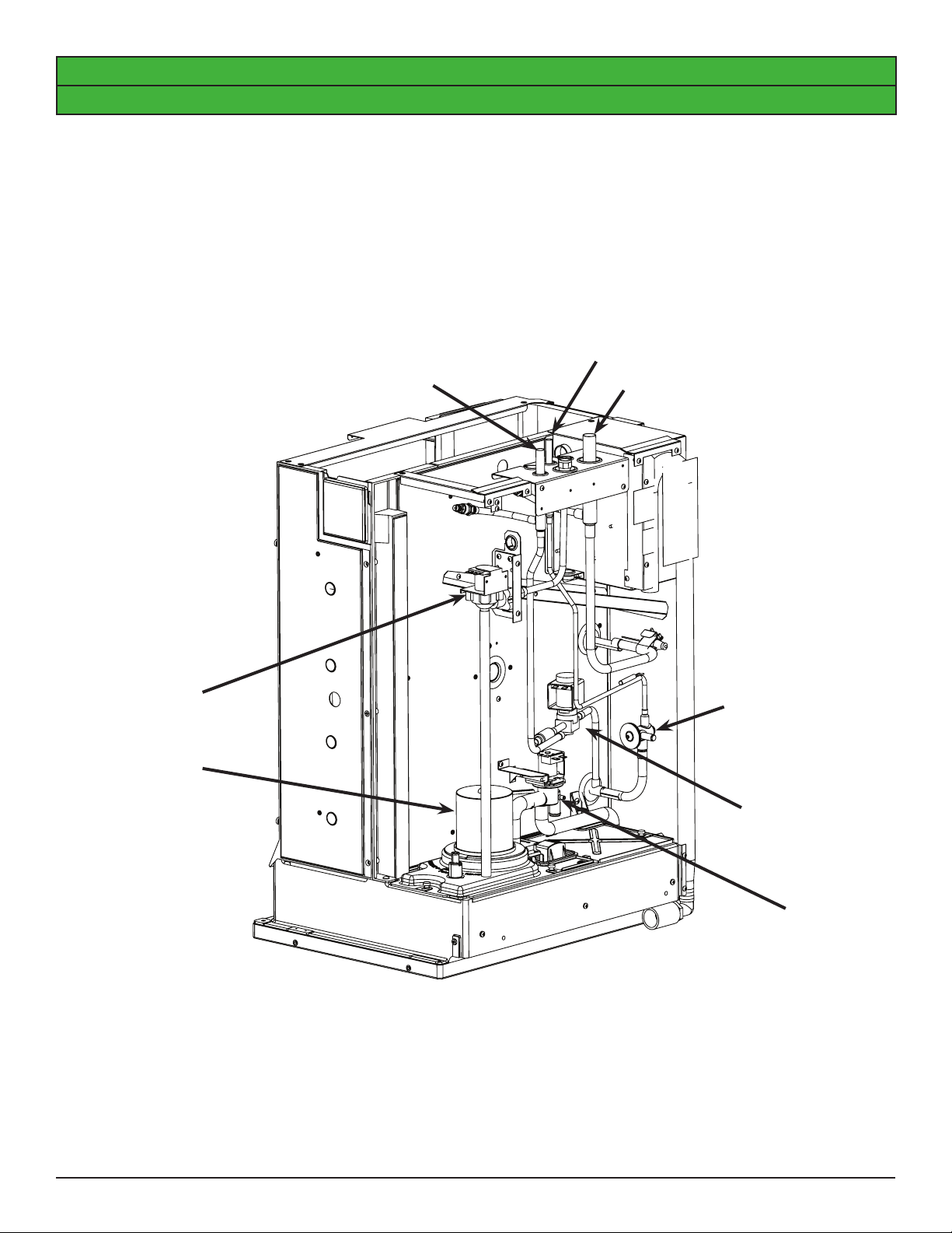
Condensing Unit.
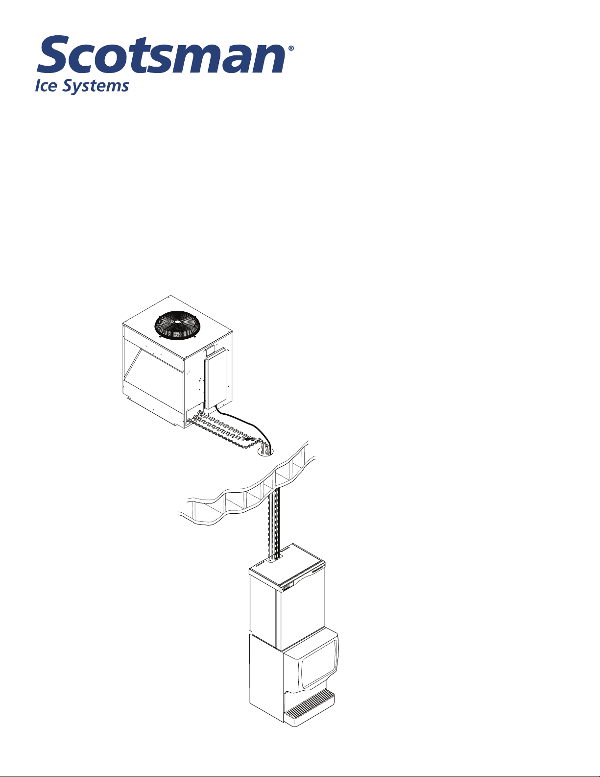
The new condensing unit is illustrated below. The ECC0800, ECC1200 and ECC1410 have one condenser
coil, while the ECC1800 has two. The coils are mounted at an angle between the compressor and fan. Airow
is in the side and out the top.
Refrigeration connections are on the side, near the base. The connections are three ball valves with stub
outlets. The ball valves ship closed, the receiver contains the refrigerant charge for the system. Schrader
access valves are on the outside of the ball valves so the interconnecting tubing can be evacuated after
brazing.
Electrical
Junction Box
Coil
Location of
Second Coil
Compressor
Dome Pressure
Suction
Pressure
Discharge
Pressure
Communication
Cable Connection
Liquid
The electrical power supply connects to the wires in the junction box near the top of the condensing unit. The
communication cable that connects to the ice making head routes thru a bushing near the base and routes to a
connector on the side of the control box.
Vapor
Suction
Page 2
Page 3
New Eclipse Technical Review
Ice Making Head.
There are three ice making heads for the New Eclipse: EH222-C, EH330-C and EH430-C. The EH222-C is
shown below. All have stubs for braze connections to the interconnecting tubing to the condensing unit. The
stubs are at the top, located with the water inlet tting, communication cable and power cord.
The EH222 has a single evaporator, the EH330 has two, twelve inch evaporators and the EH430 has two
eighteen inch evaporators.
The communication cable allows the head to operate the condensing unit. It switches it on and off, and also
controls the freeze and harvest cycles.
Vapor
Liquid
Suction
Inlet Water
Solenoid Valve
Water Pump
TXV
Vapor Valve
Purge Valve
Page 3
Page 4

New Eclipse Technical Review
The refrigeration schematic below illustrates the refrigerant system. The ice making head and condensing unit
are connected by three refrigerant tubes:
• 3/8 in OD Liquid line
• 1/2 in OD Vapor Line
• 3/4 in OD Suction line
Condenser
Liquid Inlet
Valve (NO)
Check Valve
Discharge Line
CPR Valve
Head Pressure
Valve
Bypass Valve
Compressor
Interconnecting
Tubing
Suction
Line
Accumulator
Page 4
Receiver
Vapor Line
Liquid Line
Condensing Unit
TXV
Ball Valves
Evaporator
Vapor Valve
Ice Making Head
Page 5

New Eclipse Technical Review
The ice making head contains one or two evaporators, each with its own TXV and vapor inlet valve. The
control system is also located there as are the pump, inlet water solenoid valve and purge valve.
The condensing unit contains most of the refrigeration components, including the compressor, condenser, fan
motor, crankcase pressure regulating valve, receiver, accumulator, headmaster, condenser bypass valve and
liquid inlet valve.
A communication cable connects the controller and two relays in the ice making head to the contactor and
solenoid valves in the compressor package. The Contactor relay in the head is operated by the controller and
has power during ice making. The Hot Gas Valve relay is powered by the controller only during harvest and
connects power in the condensing unit to the bypass valve and liquid inlet valve.
Refrigeration System Operation, refer to the schematic on the opposite page.
During Freeze,
• The compressor is operating.
• The vapor inlet and condenser by pass valves are closed.
• The normally open liquid line inlet valve is open.
• The headmaster is open between condenser inlet and liquid outlet.
Under low ambient/low pressure conditions, the headmaster valve closes the liquid outlet of the condenser and
opens a bypass route to direct refrigerant gas to the receiver inlet until discharge pressure builds back up to
the headmaster’s set point.
From the receiver liquid outlet, liquid refrigerant ows into the liquid line and into the ice making section.
At the ice making section, the refrigerant ows into the three expansion valves.
After the evaporator, low-pressure refrigerant gas ows into the suction line, which carries it back to the
condensing unit, where it enters the accumulator. The accumulator includes a loop of the liquid line inside
the tank, not illustrated in the schematic. In the accumulator most of any liquid carried with the suction gas is
separated and only vapor ows out of the accumulator through the CPR valve and to the compressor where
the cycle continues.
Suction pressure during freeze will be the same at the compressor or at the evaporators.
During harvest,
• The bypass and vapor valves are energized and open.
• The liquid inlet valve is energized and closed.
• The side port of the receiver releases high pressure gas into the vapor line.
• The CPR valve limits the compressor dome suction pressure to a pre-set maximum; evaporator pressure
(measured at the suction shut off valve) will be higher.
Refrigerant Recovery and System Evacuation Notice
In the event the refrigerant must be recovered from this system and the system evacuated, recover and
evacuate from the three ball valve access valves.
Page 5
Page 6

New Eclipse Technical Review
EH222 Schematic Diagram
L1
TRANSFORMER
LINE
12V
HOT GAS
VALVE
HGV
RELAY
CONTACTOR
RELAY
HARVEST
ASSIST
SOLENOID
L2
TO COMPRESSOR
SECTION
WATER
LEVEL
SENSOR
DUMP
VALVE
ELECTRONIC CONTROL
SUMP
TEMP.
DISCHARGE
TEMP.
ICE
THICKNESS
PROBE
CURTAIN
SWITCH 1
WATER
PUMP
WATER VALVE
CURTAIN
SWITCH 2
Page 6
Page 7

New Eclipse Technical Review
ECC Three Phase Schematic Diagram
Page 7
Page 8

New Eclipse Technical Review
Retrot Information
There may be need to retroft a head with an existing condensing unit. This chart lists the potential
combinations and actions needed.
When Replacing a Head:
Original Head Size Original Model /Compressor ECC Model / Compressor Replace head?
EH222 800 C0800CP / CS10 ECC0800 / CS10 Use EH222 C
EH222 1000 C1410CP / CS14 ECC1410 / CS14 Use EH222 C
EH330 1200 C1200CP / CS18 ECC1200 / CS18 Use EH330 C
EH430 1400 C1410CP / CS14 ECC1410 / CS14 Use EH430 C
EH430 1800 C1800CP / CS24 ECC1800 / CS24 Use EH430 C
EH430 2000 C2000CP / CS27 no longer available Use EH430 C
CME810 800 CP886 / CS12 - Use EH222, Rewire CP
CME810 1000 CP1086 / CS18 - Use EH222, Rewire CP
CME1386 1300 CP1316 / CS20 - Use EH430, Rewire CP
CME1686 1600 CP1316 / CS20 - Use EH430, Rewire CP
CME2086 2000 CP2086 / Scroll - Replace system
Rewire CP means adding a transformer to operate the compressor and harvest relays that are in the ice
machine head.
When Replacing a CP or Condensing Unit:
Head Size Original Model /Compressor ECC Model / Compressor Replace Condensing Unit?
EH222 800 C0800CP / CS10 ECC0800 / CS10 Use ECC0800
EH222 1000 C1410CP / CS14 ECC1410 / CS14 Use ECC1410
EH330 1200 C1200CP / CS18 ECC1200 / CS18 Use ECC1200
EH430 1400 C1410CP / CS14 ECC1410 / CS14 Use ECC1410
EH430 1800 C1800CP / CS24 ECC1800 / CS24 Use ECC1800
EH430 2000 C2000CP / CS27 no longer available not available
CME810 800 CP886 / CS12 - Use ECC0800, Rewire ECC
CME810 1000 CP1086 / CS18 - Use ECC1410, Rewire ECC
CME1386 1300 CP1316 / CS20 - Use ECC1200, Rewire ECC
CME1686 1600 CP1316 / CS20 - Use ECC1200, Rewire ECC
CME2086 2000 CP2086 / Scroll - Replace system
Rewire ECC means removing the transformer that is intended operate the compressor and harvest relays that
are in the EH ice machine head. The transformer to operate the system is in the CME head.
Note: Not all voltages are available to retrot condensing units.
Page 8
 Loading...