

Page 1
Installation Instructions for
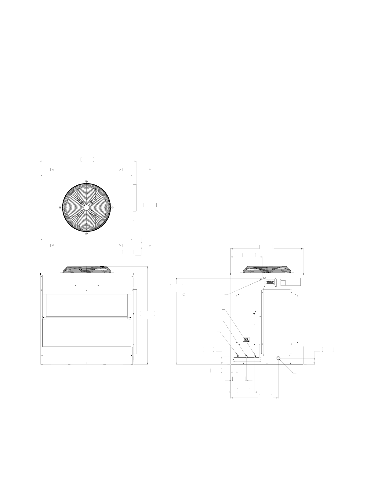
Prodigy Eclipse Condensing Unit
models ECC0800, ECC1200, ECC1410, ECC1800
TOP VIEW
992.81
39.09
814.22
32.06
FRONT VIEW
32.05
1.26
TYP.
1009.65
39.75
887.73
34.95
.88" ELECTRICAL INLET
1/2" COOL VAPOR LINE
3/4" SUCTION LINE
3/8" LIQUID LINE
83.67
3.29
SIDE VIEW
LINE SET AND ELECTRICAL ATTACHMENT SIDE
330.86
13.03
74.12
2.92
163.02
6.42
248.87
9.80
750.06
29.53
491.69
19.36
INTERFACE HARNESS
ACCESS HOLE
63.50
2.50
17-3456-01
Page 2

Introduction
A remote low side cuber system consists of two systems: an ice making section and a remote condensing unit.
This instruction manual covers the Condensing Unit.
Unpack
1. Remove the carton.
2. Disconnect condensing unit from skid
3. Remove both side panels.
4. Locate and retain communication wire.
Placement
The footprint of the condensing unit is 39” x 32”. Have roof equipment rails prepared for it. Plan on attaching
the unit per local building codes, including any hurricane requirements.
Location
The condensing unit requires unobstructed air ow to operate efciently. A four foot space between each intake
side and a wall or other cabinet is recommended.
Do not place where it will pick up hot discharged air from an air conditioner or other refrigeration system
condensing unit.
Space must also be reserved for service on the condensing unit.
Roof preparation
Most installations of this system will place the condensing unit on the roof of a building. The roof must be
physically able to accept the load of the equipment and the roong material must be prepared to prevent water
leaks.
Roof Piercing:
The roof (or wall) must have a passage large enough for the three refrigeration tubes and the control wire
to pass through. The minimum recommended size is 4” ID. In most areas the power supply may also pass
through the same passage. If there isn’t a passage one must be created. In most cases this must be done by a
licensed and bonded roofer in order to maintain the roof’s integrity.
Roof Pipe Curb or Pitch Pocket:
To avoid potential kinking of the refrigeration tubing, avoid small, tight radius types of covers on pitch pockets.
Suggestions:
• Orient the assembled unit so that the unit’s refrigeration connections are nearest to the tubing.
• Do NOT place the unit directly onto roof rock.
Position the unit
In most cases a crane will be required to lift the unit to a roof location.
Mount unit to roof rails or curbs and secure with lag screws or similar eld supplied fasteners.
Electrical ConnectIon
Electrical power must be supplied to the condensing unit, it will be separate from the head. Locate condensing
unit dataplate for Voltage, Phase, Miniumum Circuit Ampacity and Maximum Fuse Size.
Page 3

Model Voltage Minimum
Circuit
Ampacity
ECC0800-32 208-230/60/1 14.8 20 192 32 x 39 x 39.75
ECC0800-3 208-230/60/3 10.6 15 192 32 x 39 x 39.75
ECC1200-32 208-230/60/1 17.8 20 224 32 x 39 x 39.75
ECC1410-3 208-230/60/3 9.1 15 224 32 x 39 x 39.75
ECC1410-32 208-230/60/1 14.5 20 224 32 x 39 x 39.75
ECC1800-3 208-230/60/3 19.0 20 232 32 x 39 x 39.75
Connect electrical power to the wires in the junction box on the side of the unit. A eld supplied service
disconnect is recommended. Use caution when mounting the disconnect, do not drill into condenser coils.
Route interconnecting communication wire harness thru access hole and connect to control box. The harness
is included with the condensing unit. One end plugs into the ice making section and the other into the
condensing unit. The system will NOT operate without this harness.
Refrigeration Tubing
Important: Minimize the amount of tubing exposed outdoors.
The line set must be routed between the condensing unit and the ice maker’s location. During the transition
from quick connects to braze connections, the ice maker or line set may or may not have quick connects, use
this chart as a guideline for the proper action based on what is available at the site.
Maximum
Fuse Size
System
Charge
Cabinet Size
w x d x h
Condensing unit has sweat connections
Ice making head has sweat connections If line set does not have quick connects, route and use as is.
If line set has quick connects, recover refrigerant from line set
and cut all quick connects off.
Ice making head has quick connects If line set has quick connects, recover refrigerant from line set
and cut one end of quick connects off.
If line set does not have quick connects, must use KTE6-EH
stub kit to add for ice machine end.
In all cases the line set will need to be shortened to t.
Do NOT leave excess line set exposed outdoors, especially on a roof.
Line Routing:
• Allowed: One rise after a drop.
• Allowed: One drop after a rise.
• Not Allowed: More than one rise after a drop
• Not Allowed: More than one drop after a rise.
17-3456-01
Page 4

Connect Refrigeration
Requires brazing, steps must be performed by an
EPA certied type II or higher technician.
At Head:
1. Remove protective plugs from all three
connections and vent the nitrogen from the ice
machine.
2. Route the each of the three tubes to its
connection.
3. Remove the top panel and attach a refrigeration
hose with depressor to the 1/2” vapor line access
valve so the valve is OPEN. This is a vent for
nitrogen purging.
4. Remove screws holding tubing bracket to back
panel and lower it out of the way for brazing.
5. Clean tubing ends and position into stubs.
At Condensing Unit
1. Conrm connection valves are fully closed.
3. Pull tubing bracket up and secure to back panel.
At Condensing Unit
1. Remove nitrogen source.
2. Return valve cores to access valves.
3. Connect vacuum pump to all three access valves
(use two manifolds or two extra hoses and a tee)
and evacuate the tubing and head to at least a
300 micron level.
4. Remove vacuum pump and add R-404A vapor to
all three tubes to provide a positive pressure.
5. Leak check the braze connections and repair any
leaks.
6. Open all three valves to full open.
Note: The full refrigerant charge is contained in the
receiver of the ice machine.
2. Remove protective plugs from all three
connections.
3. Remove caps from access valve connections.
4. Remove cores from access valves.
5. Connect refrigeration hoses to access valves.
6. Connect dry nitrogen source to liquid line
connection and vapor line connection.
7. Shorten tubing to correct length, clean ends and
insert them into valve stubs.
Note: Be sure tube and stubs are round, dress with
swage tool if needed.
8. Add heat sink material to ball valve body.
9. Open nitrogen and ow 1 psi nitrogen into liquid
line and vapor line tubes and braze the liquid
line, vapor line and suction line tubes to the valve
stubs.
At Head
1. With nitrogen owing from condensing unit, braze
the liquid, vapor and suction line connections.
2. Remove refrigeration hose from head. Be sure
valve cap is on tight.
 Loading...