

Page 1
Service Manual
for Prodigy Eclipse Cubers models EH330 C and
EH430 C, with ECC Condensing Unit ECC1200,
ECC1410, ECC1800
Includes Prodigy Plus D Models
Page 2

EH330, EH430 and ECC Condensing Unit
Remote Low Side Cuber Service Manual
Introduction:
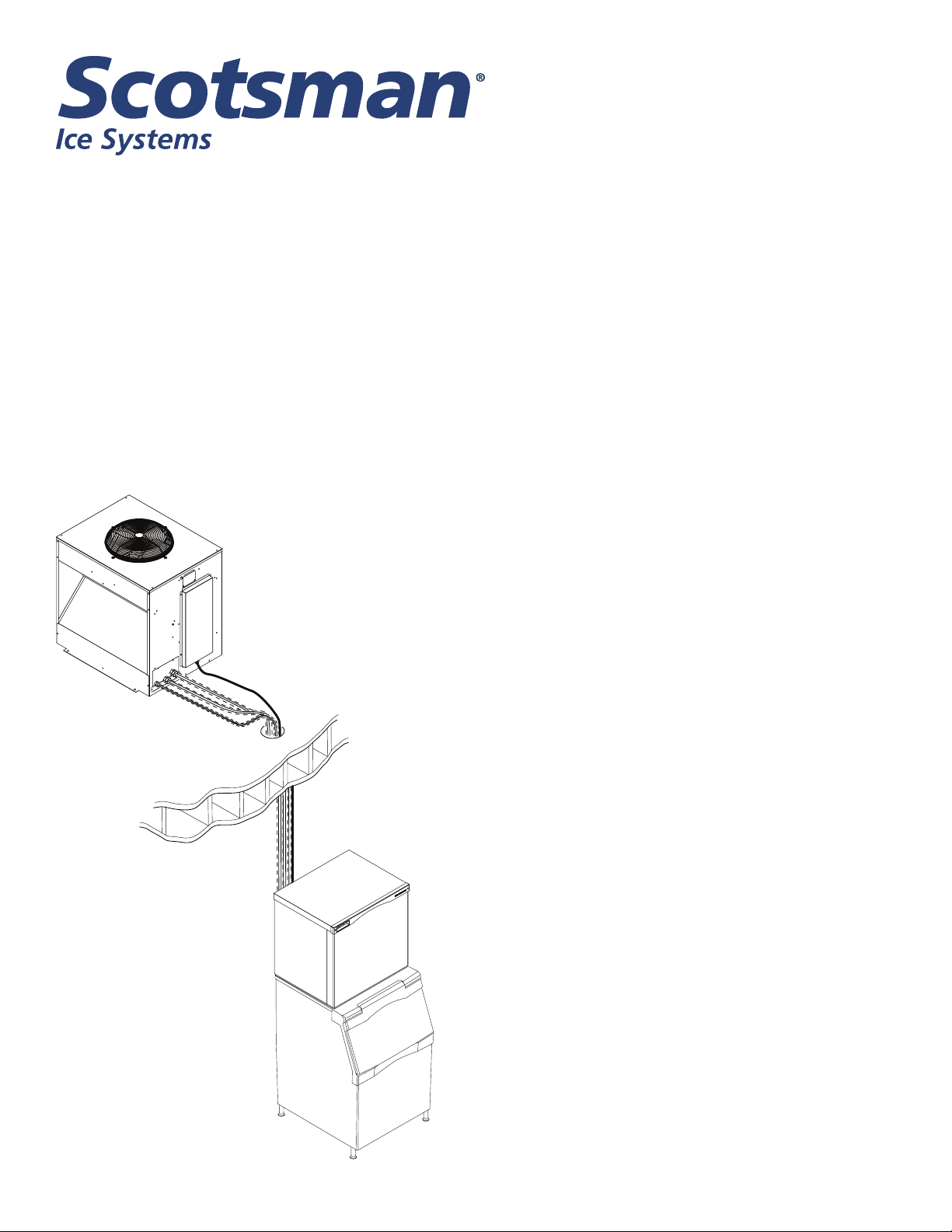
This manual covers the assembly, installation, start up, operation and maintenance of the 1200, 1400 and
1800 remote low side cuber systems.
Contents
Conguration .......................... Page 2
Technical Specications ................. Page 3
Cabinet Drawings, EH330C Ice Making Head Page 4
Cabinet Drawings, EH430C Ice Making Head Page 5
Cabinet Drawings, EH330D Ice Making Head Page 6
Cabinet Drawings, EH430D Ice Making Head Page 7
Cabinet Drawings, ECC Condensing Unit .... Page 8
Pre-Installation Details. . . . . . . . . . . . . . . . . . . Page 9
Create the System ...................... Page 10
System Example ....................... Page 11
Place Remote System ................... Page 12
Tubing ............................... Page 13
Place Ice Making Head .................. Page 14
EH430) .............................. Page 30
Controller Information ................... Page 32
Operation ............................. Page 33
System Operation: ...................... Page 34
Refrigeration Details: .................... Page 35
Freeze Cycle Sequence of Operation ....... Page 36
Harvest Cycle Sequence of Operation ...... Page 37
Control Safeties ........................ Page 38
Controller Operation .................... Page 39
Service Diagnosis ...................... Page 40
Service Diagnosis ...................... Page 41
Service Diagnosis ...................... Page 42
Refrigeration Data ...................... Page 43
Refrigeration Data - 1800 ................ Page 44
Condensing Unit Electrical ............... Page 15
Water and Drain ....................... Page 16
Connect Refrigeration ................... Page 17
Complete the Installation ................. Page 18
Reference for Start Up: Controller Operation . Page 19
Initial Start Up ......................... Page 20
Ice Thickness and Water Purge Adjustment .. Page 21
Cleaning, Sanitation and Maintenance ...... Page 22
Operational Characteristics 1200 lb system (ECC1200/
EH330) .............................. Page 29
Operational Characteristics 1400 lb system (ECC1410/
EH430) .............................. Page 29
Operational Characteristics 1800 lb system (ECC1800/
Refrigerant Recovery. . . . . . . . . . . . . . . . . . . . Page 45
System Isolation ....................... Page 46
Condenser Coil ........................ Page 47
EH330-C or EH430-C Schematic Diagram .. Page 48
EH330-C or EH430-C Wiring Diagram ...... Page 49
EH330-D or EH430-D Schematic Diagram ... Page 50
EH330-D or EH430-D Wiring Diagram ...... Page 51
ECC 3 Phase Schematic Diagram ......... Page 52
ECC 3 Phase Wiring Diagram ............. Page 53
ECC 1 Phase Schematic Diagram ......... Page 54
ECC 1 Phase Wiring Diagram ............. Page 55
May 2015
Page 1
Page 3
EH330, EH430 and ECC Condensing Unit
Remote Low Side Cuber Service Manual
Conguration
A remote low side cuber system includes two
sub systems: an ice head section and a remote
condensing unit. Additionally, there are several
models of each sub-system and this manual covers
all of them.
The ice making sections are designed for use indoors
in a controlled environment. The remote condensing
units are designed to operate outdoors. Each subsystem has limits for power, water and temperature.
Operational Limitations:
Minimum Maximum
Air Temp (IH) 50oF 100oF.
Air Temp (CU) -20oF. 120oF.
Water Temp 40oF. 100oF.
Water Pressure 20 psi 80 psi
Water Conductivity 10 microSiemens/cm
Voltage (IH) 104 126
Voltage (CU) 198 253
IH = Ice Head, CU= Condensing Unit
Warranty
Refer to the warranty coverage in effect when the
equipment was sold. Warranty statements are
included with each product.
Systems:
Each sub-system is a separate entity that carries
its own model and serial number. They must be
combined to create a remote cuber low side system.
Notes: Voltage Codes are at the end of the model
number. Codes read Voltage/Hertz/Phase. Those
related to these products include:
-1 = 115/60/1
-3 = 208-230/60/3
-32 = 208-230/60/1
Tubing kits are required to interconnect the head to
the CU
Do Not operate the machine in conditions beyond
these limitations. Doing so will void the warranty.
Scotsman ice systems are designed and
manufactured with the highest regard for safety and
performance. They meet or exceed the standards of
• 20 foot: 3BRTE20-EH,
• 35 foot: 3BRTE35-EH
• 50 foot: 3BRTE50-EH
• 75 foot: 3BRTE75-EH
UL and NSF.
Interconnecting 24 volt control wire ships in the
Scotsman assumes no liability of responsibility of
condensing unit.
any kind for products manufactured by Scotsman
that have been altered in any way, including the use
of any part and/or other components not specically
approved by Scotsman.
Scotsman reserves the right to make design changes
and/or improvements at any time. Specications and
design are subject to change without notice.
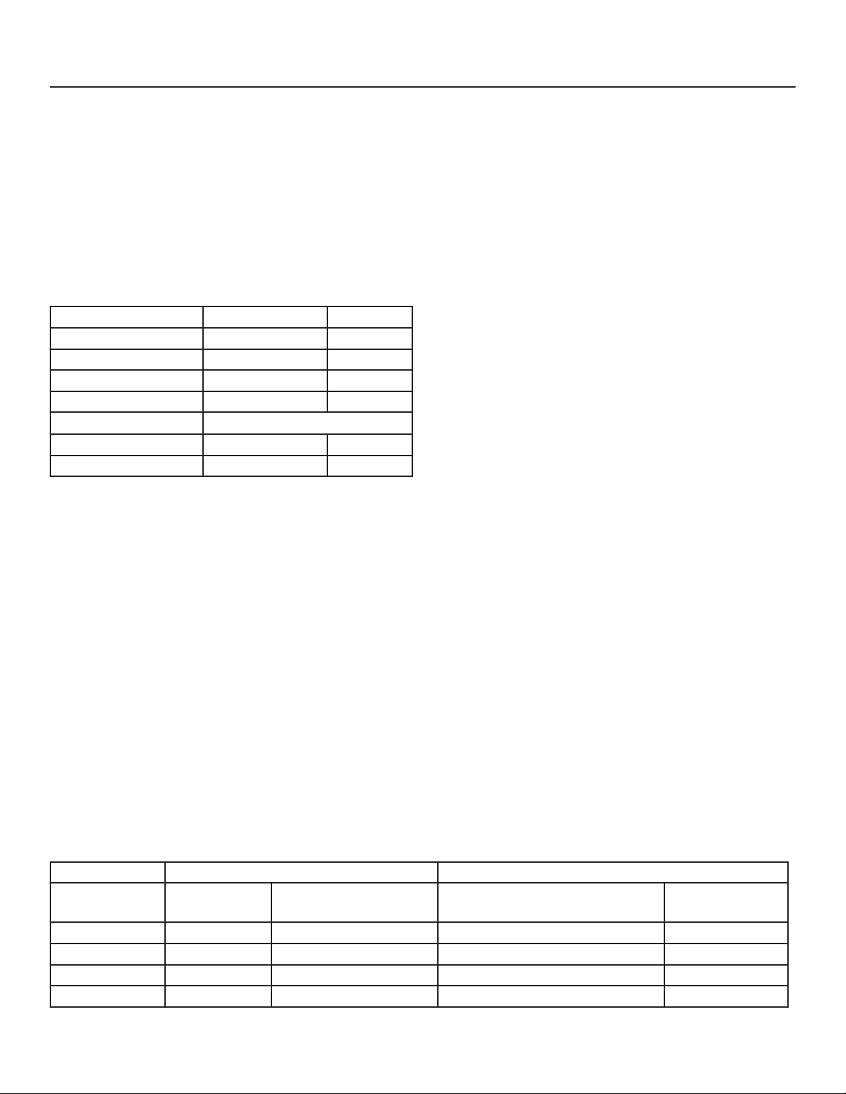
System Information
System Size Condensing Unit (CU) Ice Making Head (IH)
Model Electrical
(volts/Hz/phase)
1200 ECC1200-32A 208-230/60/1 EH330SL-1C/D or EH330ML-1C/D 115/60/1
1400 ECC1410-32A 208-230/60/1 EH430SL-1C/D or EH430ML-1C/D 115/60/1
1400 ECC1410-3A 208-230/60/3 EH430SL-1C/D or EH430ML-1C/D 115/60/1
1800 ECC1800-3A 208-230/60/3 EH430SL-1C/D or EH430ML-1C/D 115/60/1
May 2015
Model Electrical
(volts/Hz/phase)
Page 2
Page 4
EH330, EH430 and ECC Condensing Unit
Remote Low Side Cuber Service Manual
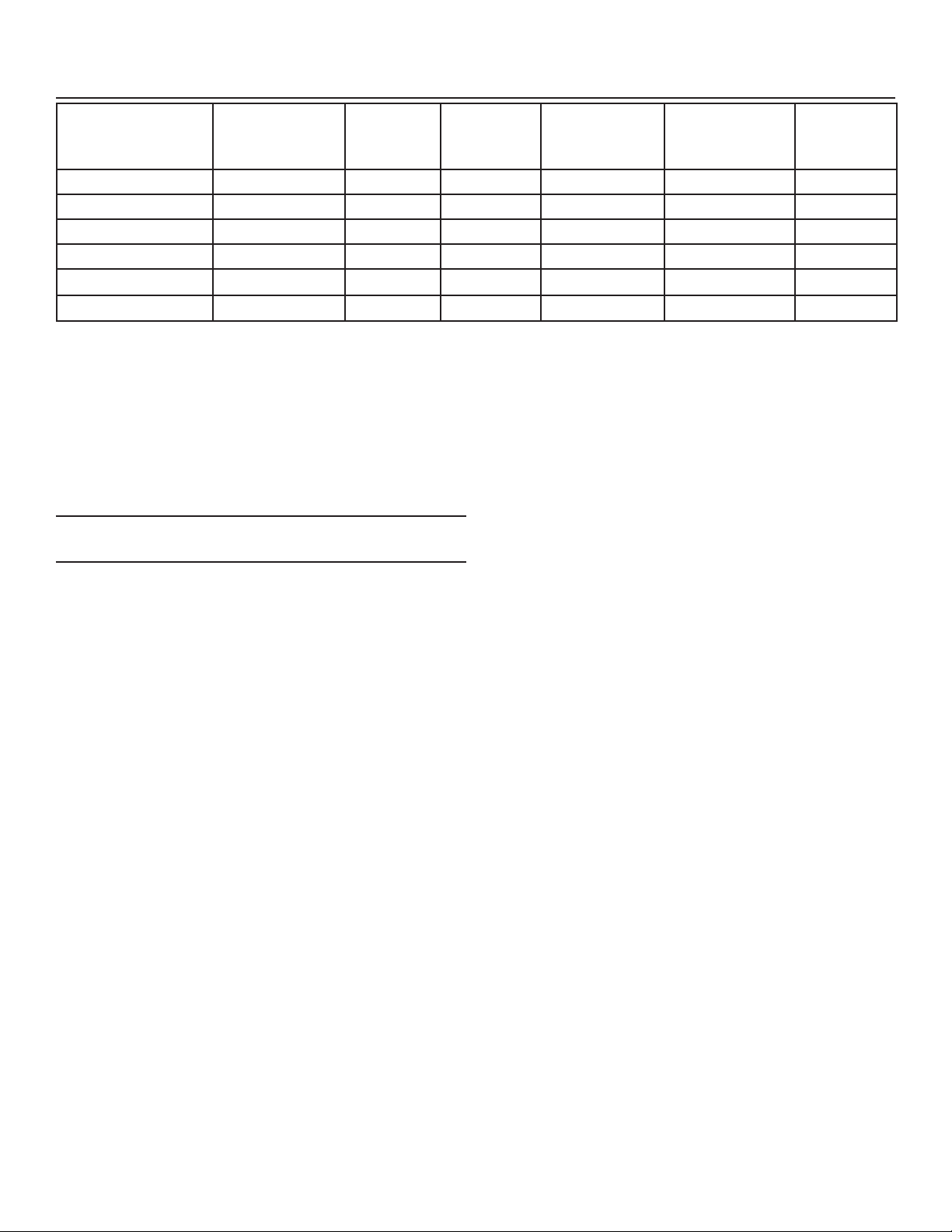
Technical Specications
Model Electrical
(volts/Hz/
phase)
EH330SL-1C or D 115/60/1 3 15 - 30 x 24 x 23 130
EH430SL-1C or D 115/60/1 3 15 - 30 x 24 x 29 165
ECC1200-32 208-230/60/1 17.8 30 224 32 x 39 x 39.75
ECC1410-3 208-230/60/3 9.1 20 224 32 x 39 x 39.75
ECC1410-32 208-230/60/1 14.5 30 224 32 x 39 x 39.75
ECC1800-3 208-230/60/3 19.0 30 232 32 x 39 x 39.75
* See Cabinet Drawings for exact dimensions.
Location Limitations
Maximum Distance between Head and Condensing
Unit: Limited to the length of the longest available
single tubing kit, 75 feet.
Maximum Condensing Unit Elevation over Ice Making
Head: 35 feet.
Note: Elevations greater than 20 feet require
installation of a suction line trap at the 20 foot mark.
Minimum
Circuit
Ampacity
Maximum
Fuse Size
Condensing unit
The dataplate on the condensing unit contains the
model number, serial number, electrical data and
system refrigerant charge.
A second plate, located behind the front panel in front
of the compressor, also lists the model number, serial
number and refrigerant charge.
System
Charge oz of
R-404A
Cabinet Size*
w” x d” x h”
Approx.
Unit Weight
(lb)
Maximum Ice Making Head Elevation over
Condensing Unit: 15 feet.
Line Routing:
• Allowed: One rise after a drop.
• Allowed: One drop after a rise.
• Not Allowed: More than one rise after a drop
• Not Allowed: More than one drop after a rise.
Model Number Locations
Ice Making Head
The dataplate on the back of the ice machine contains
the model number, serial number and electrical data.
A second plate, located behind the front panel at
the lower right front, also lists the model and serial
numbers.
July 2013
Page 3
Page 5
EH330, EH430 and ECC Condensing Unit
Remote Low Side Cuber Service Manual
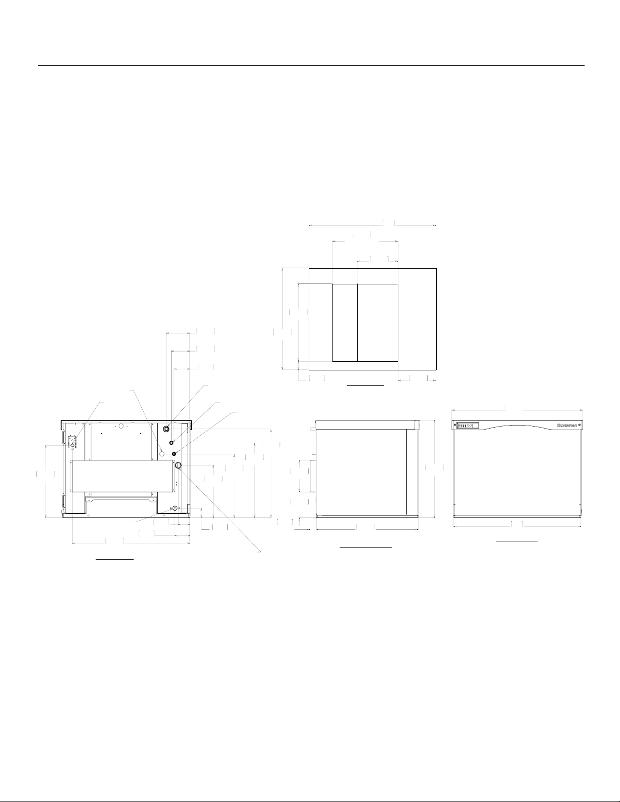
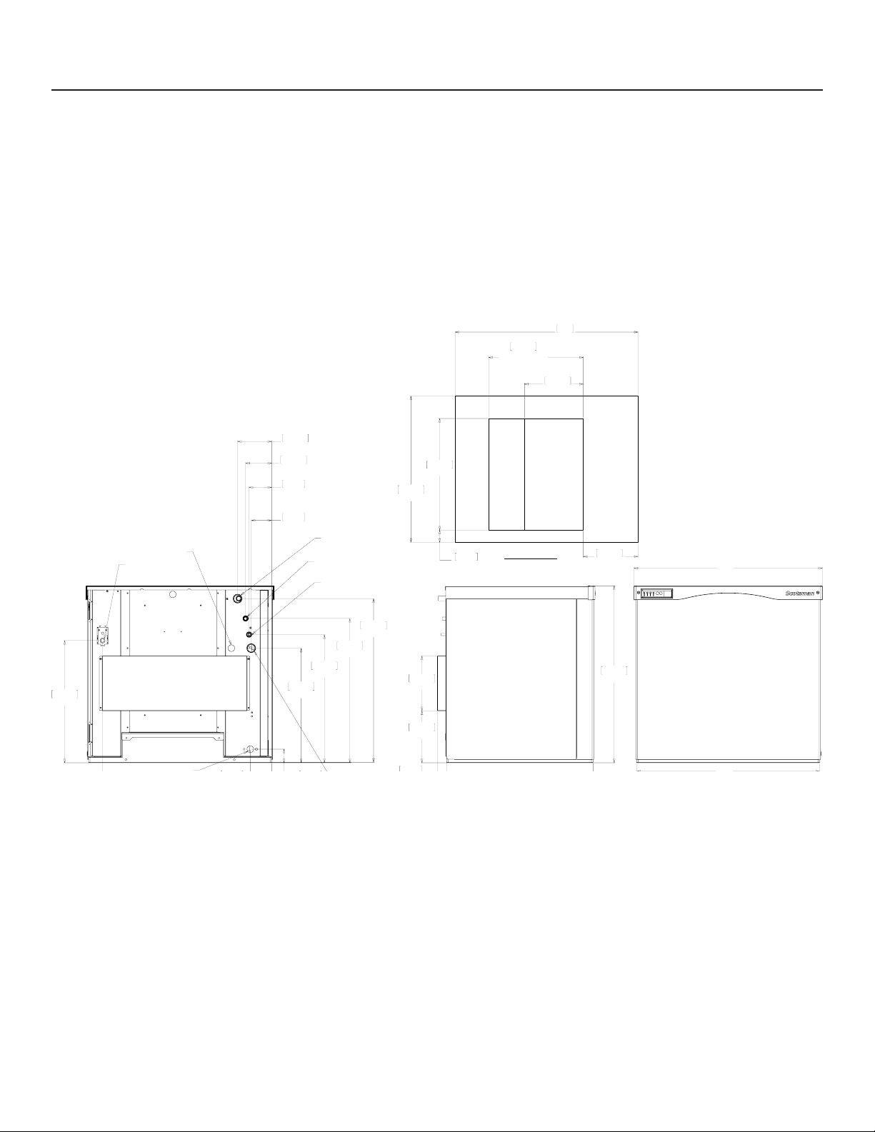
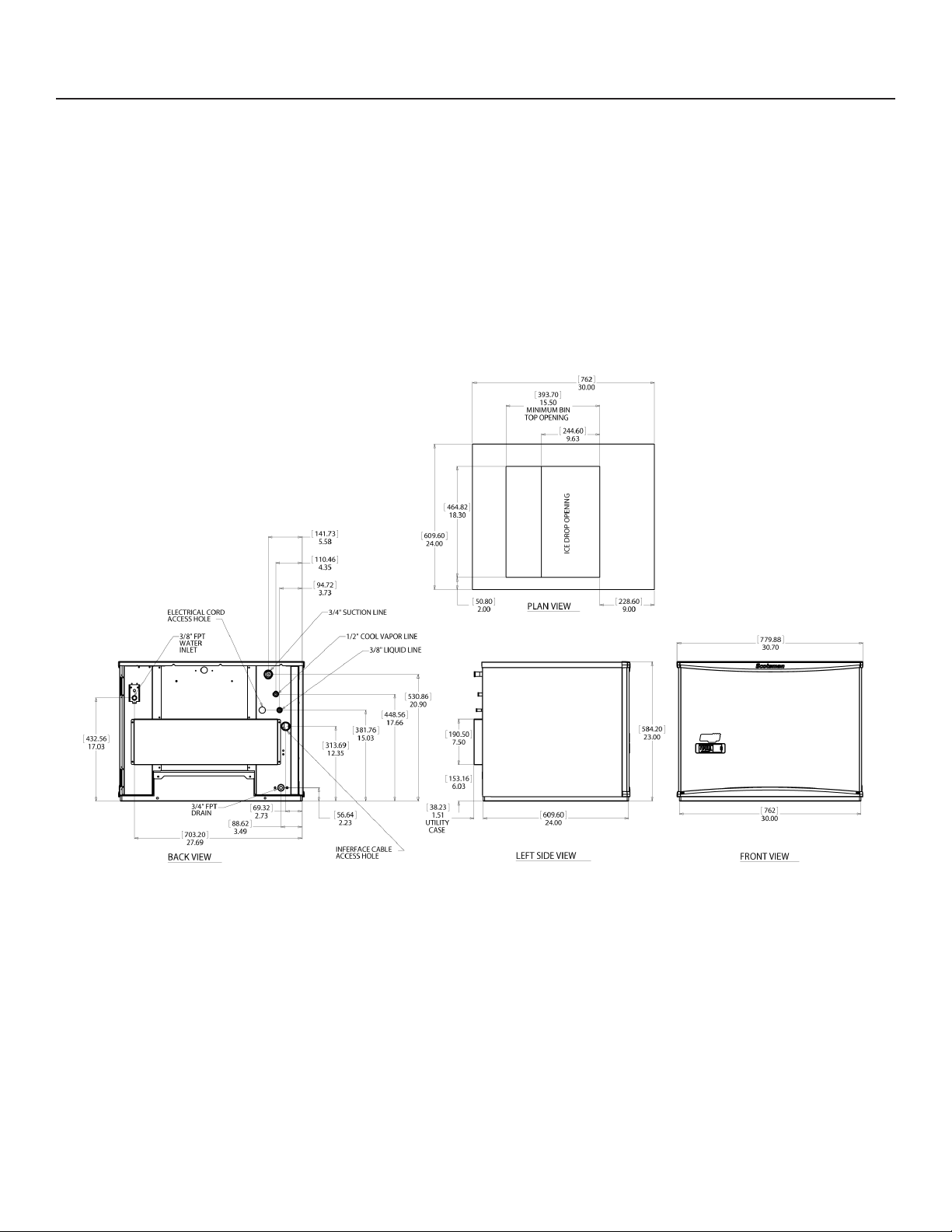
Cabinet Drawings, EH330C Ice Making Head
ELECTRICAL CORD
ACCESS HOLE
3/8" FPT
WATER
INLET
141.73
5.58
110.46
4.35
94.72
3.73
3/4" SUCTION LINE
1/2" COOL VAPOR LINE
3/8" LIQUID LINE
609.60
24.00
464.82
18.30
50.80
2.00
393.70
15.50
MINIMUM BIN
TOP OPENING
PLAN VIEW
762
30.00
244.60
9.63
ICE DROP OPENING
228.60
9.00
784.55
30.89
432.56
17.03
3/4" FPT
DRAIN
703.20
27.69
BACK VIEW
88.62
3.49
69.32
2.73
313.69
12.35
56.64
2.23
INFERFACE CABLE
ACCESS HOLE
381.76
15.03
448.56
17.66
530.86
20.90
38.23
1.51
UTILITY
CASE
190.50
7.50
153.16
6.03
609.60
24.00
LEFT SIDE VIEW
584.20
23.00
762
30.00
FRONT VIEW
July 2013
Page 4
Page 6
EH330, EH430 and ECC Condensing Unit
3/4" FPT
Remote Low Side Cuber Service Manual
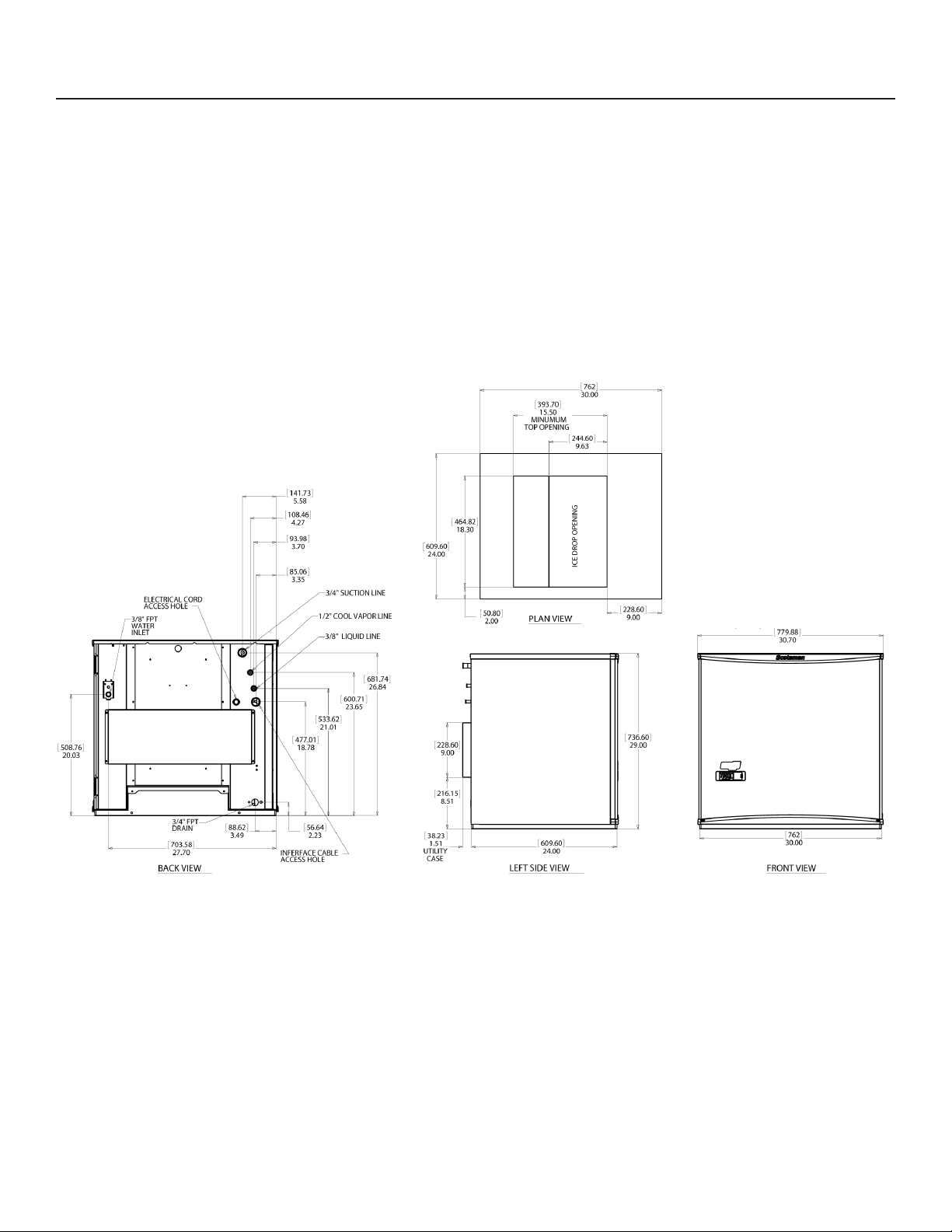
Cabinet Drawings, EH430C Ice Making Head
141.73
5.58
108.46
4.27
93.98
3.70
85.06
3.35
ELECTRICAL CORD
ACCESS HOLE
3/8" FPT
WATER
INLET
3/4" SUCTION LINE
1/2" COOL VAPOR LINE
3/8" LIQUID LINE
609.60
24.00
464.82
18.30
50.80
2.00
393.70
15.50
MINUMUM
TOP OPENING
PLAN VIEW
762
30.00
244.60
9.63
ICE DROP OPENING
228.60
9.00
30.89
508.76
20.03
477.01
18.78
533.62
21.01
600.71
23.65
681.74
26.84
228.60
9.00
216.15
8.51
736.60
29.00
July 2013
Page 5
Page 7
EH330, EH430 and ECC Condensing Unit
Remote Low Side Cuber Service Manual
Cabinet Drawings, EH330D Ice Making Head
May 2015
Page 6
Page 8
EH330, EH430 and ECC Condensing Unit
Remote Low Side Cuber Service Manual
Cabinet Drawings, EH430D Ice Making Head
May 2015
Page 7
Page 9
EH330, EH430 and ECC Condensing Unit
Remote Low Side Cuber Service Manual
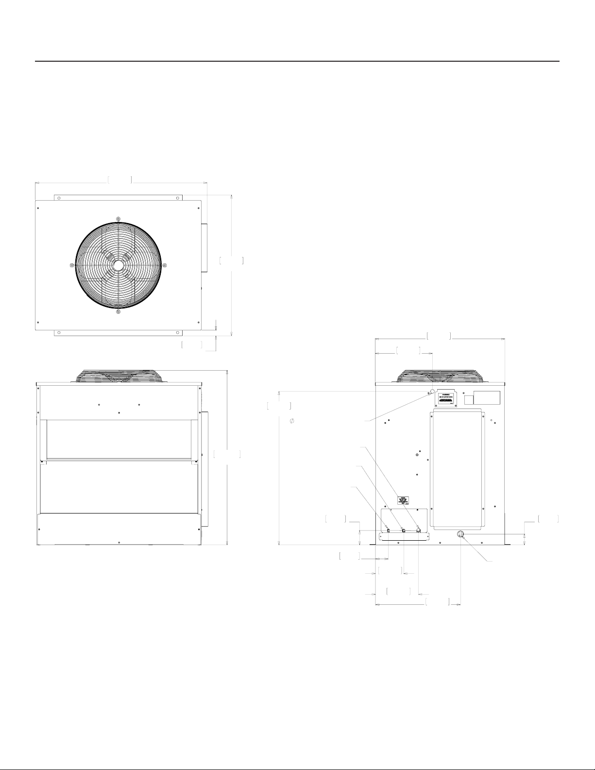
Cabinet Drawings, ECC Condensing Unit
TOP VIEW
992.81
39.09
814.22
32.06
FRONT VIEW
32.05
1.26
TYP.
1009.65
39.75
887.73
34.95
.88" ELECTRICAL INLET
1/2" COOL VAPOR LINE
3/4" SUCTION LINE
3/8" LIQUID LINE
83.67
3.29
SIDE VIEW
LINE SET AND ELECTRICAL ATTACHMENT SIDE
330.86
13.03
74.12
2.92
163.02
6.42
248.87
9.80
750.06
29.53
491.69
19.36
INTERFACE HARNESS
ACCESS HOLE
63.50
2.50
July 2013
Page 8
Page 10

EH330, EH430 and ECC Condensing Unit
Remote Low Side Cuber Service Manual
Pre-Installation Details
Note: The ice making head cannot be stacked
vertically.
Accessories such as bin adapters and tubing kits are
required to complete the installation.
Dispenser Adapter Kits:
• Scotsman ID200 or ID250: KBT44
Bin Adapter Kits:
• B948S: KBT22A
Tubing Kits:
• 20 foot: 3BRTE20-EH
• 35 foot: 3BRTE35-EH
• 50 foot: 3BRTE50-EH
• 75 foot: 3BRTE75-EH
Note: Line set may have quick connects. See
refrigeration system detailed instructions connection
details.
Items required for installation:
Water
Pure water does not exist. All water supplies contain
some amounts of impurities, although potable water
is, by denition, t for human consumption. Because
the contents of the water to an ice machine directly
impact its performance, consideration should be given
to improving the water’s quality.
There are two ways water can contain impurities:
in suspension or in solution. Suspended solids can
be ltered out of the water. In solution or dissolved
solids must be diluted or treated. Water lters are
recommended to remove the suspended solids.
Some lters or lter systems have treatment
chemicals in them for treating the suspended solids.
This ice machine has an adjustment for the amount
of water rinsed or purged. Water use adjustments
are customer convenience adjustments; they are not
factory defects and are not covered by warranty.
• Ice making head
• Condensing unit (includes interconnecting control
system wire)
• Tubing kit. 20’, 35', 50’ or 75’ triple line set (liquid,
vapor and suction)
• Bin or dispenser adapter
Special Considerations
The ice making section’s footprint is 30” wide by 24”
deep plus another 1.5” for a utility chase on the back
panel. The refrigeration connections can be made to
go up or out the back by bending the line set tubing.
The electrical power cord and the water inlet line can
also be routed through either of those areas. The
drain may be routed out the back or to the left side.
July 2013
Page 9
Page 11

EH330, EH430 and ECC Condensing Unit
Remote Low Side Cuber Service Manual
Create the System
Plan the installation. The system consists of three
parts: the ice making head, the condensing unit and
the interconnecting tubing. Of these, the biggest
variable is the interconnecting tubing.
Tubing: The tubing consists of three insulated and
sealed soft copper tubes. One tube, the liquid line,
is 3/8” OD. The vapor tube is ½” OD and the suction
tube is ¾” OD. A site inspection will determine what
length of tubing is required for the installation.
In 2013 Scotsman made a change to the Eclipse
tubing kits:
• Prior Tubing Kits: They each contain a small
holding charge of R-404A and have quick
connects at the ends.
• Current Tubing Kits: The do not contain any
refrigerant and do not have quick connects.
Either type can be used to connect the head and
condensing unit.
Quick Connect type: Check ice making head and
condensing unit for quick connects. If none, recover
refrigerant from tubing and cut the quick connects off.
Condensing Unit: Electrical power must be supplied to
the condensing unit, it will be separate from the head.
The remote tubing connections are at the top of the
machine, and connections should not be made until
the machine is nearly in its nal installed position.
The 115/60 Hz ice making section is cord connected
and requires an outlet within 6 feet of the installation.
Interconnecting wires: A low voltage interconnecting
wire harness is included with the condensing unit.
One end plugs into the ice making head and the other
into the condensing unit. The system will NOT operate
without this harness.
Exposed tubing: Minimize the amount of tubing
exposed outdoors.
If the head or condensing unit has a quick connect,
recover refrigerant and only cut off the quick connect
at the system with the stub connections.
Tubing without quick connects: Check head and
condensing unit, if neither have quick connects, use
as is. If one or both do, obtain kit KTE6 to add quick
connects to the line set.
Excess tubing must be shortened at the job site.
Installations with greater than 20 feet of vertical lift
between ice machine and the compressor require
a suction line trap. The suction line requires careful
handling and large radius bends to prevent kinking.
Roof mounting: Some installations will require the use
of a hoist to lift the components to the roof.
Pad mounting: The condensing unit may be located
below the ice making section, up to a limit of 15 feet.
Distance from unit: Limited to the length of the
available tubing.
Elevation: Condensing unit limited to 35 feet above
the ice making head.
July 2013
Page 10
Page 12
EH330, EH430 and ECC Condensing Unit
Remote Low Side Cuber Service Manual
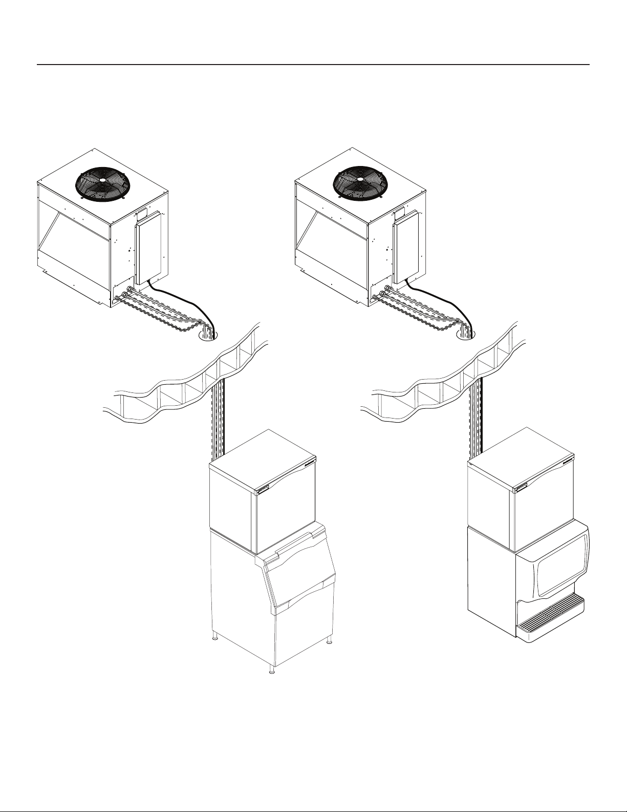
System Example
July 2013
Page 11
Page 13
EH330, EH430 and ECC Condensing Unit
Remote Low Side Cuber Service Manual
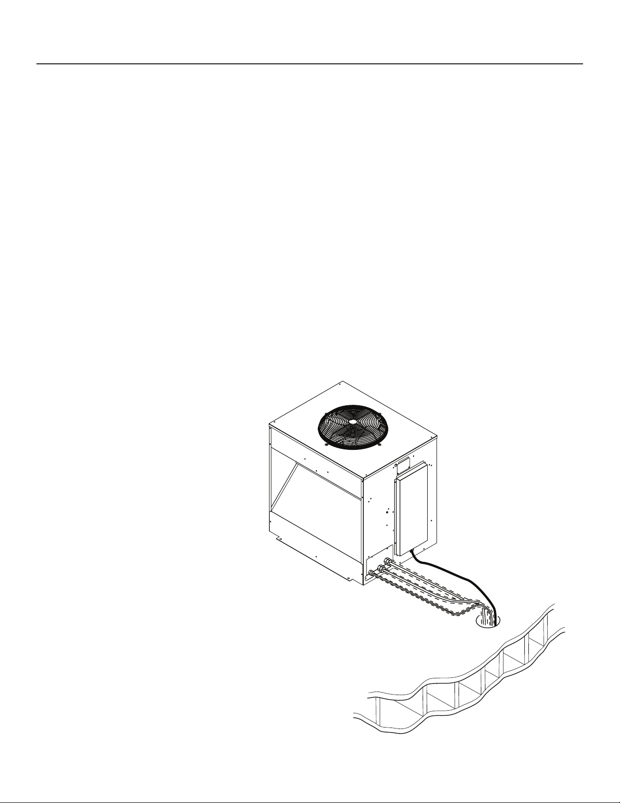
Place Remote System
Roof preparation
Most installations of this system will place the
condensing unit on the roof of a building. The roof
must be physically able to accept the load of the
equipment and the roong material must be prepared
to prevent water leaks.
Follow local codes for the placement and attachment
of the equipment.
Location
The condensing unit requires unobstructed air ow
to operate efciently. A four foot space between
each intake side and a wall or other cabinet is
recommended.
Do not place where it will pick up hot discharged air
from an air conditioner or other refrigeration system
condensing unit.
Space must also be reserved for service on the
condensing unit.
Roof Pipe Curb or Pitch Pocket:
To avoid potential kinking of the refrigeration tubing,
avoid small, tight radius types of covers on pitch
pockets.
Suggestions:
In most cases a mechanical lift, boom truck or crane
will be required to hoist the condensing unit.
Mount unit to roof rails or curbs and secure with lag
screws or similar eld supplied fasteners.
Orient the assembled unit so that the unit’s mounts
are parallel to the pitch of the roof to allow water to
drain freely.
Do NOT place the unit directly onto roof rock.
Roof Piercing:
The roof (or wall) must have an opening
large enough for the three refrigeration tubes
and the control wire to pass through. The
minimum recommended size is 4” ID. In
most areas the power supply may also pass
through the same passage. If there isn’t a
passage one must be created. In most cases
this must be done by a licensed and bonded
roofer in order to maintain the roof’s integrity.
July 2013
Page 12
Page 14
EH330, EH430 and ECC Condensing Unit
Remote Low Side Cuber Service Manual
Tubing
The line set must be routed between the condensing unit and the ice maker’s location. During the transition
from quick connects to braze connections, the ice maker, condensing unit and line set may or may not have
quick connects, use this chart as a guideline for the proper action based on what is available at the site.
Condensing unit has sweat connections Condensing unit has quick connects
Ice making head has
sweat connections
Ice making head has
quick connects (prior
models of EH330 and
EH430)
If line set does not have quick connects,
route and use as is.
If line set has quick connects, recover
refrigerant from line set and cut all quick
connects off.
If line set has quick connects, recover
refrigerant from line set and cut one end
of quick connects off.
If line set does not have quick connects,
must use KTE6-EH stub kit to add for ice
machine end.
Compressor packs C1200CP,
C1410CP and C1800CP may be
connected to this head and will have
quick connects. If line set has quick
connects, recover refrigerant from line
set and cut one end of quick connects
off.
If line set does not have quick
connects, must use KTE6-EH stub kit
to add for condensing unit end.
If line set does not have quick
connects, must use KTE6-EH stub kit
to add for ice machine end.
Use the quick connects to make the
connection.
In all cases the line set will need to be shortened to t.
Do NOT leave excess line set exposed outdoors,
especially on a roof.
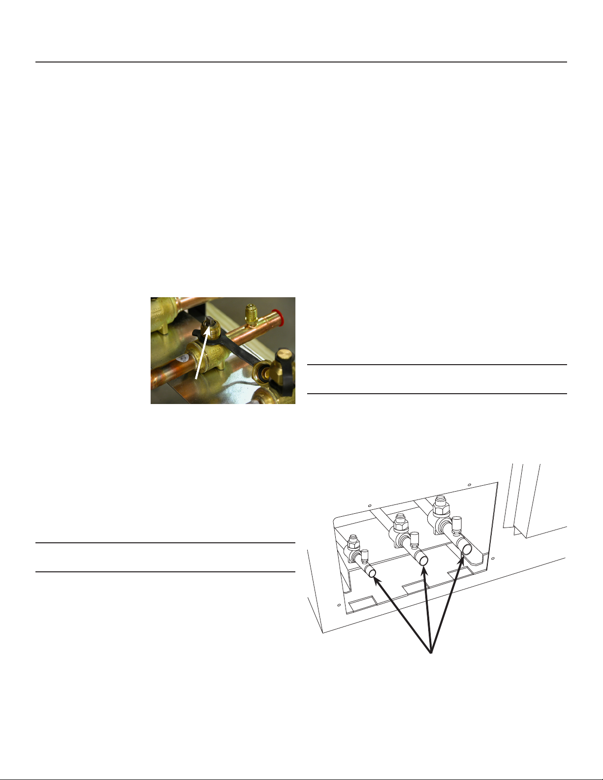
Refrigerant Recovery and System Evacuation Notice
In the event the refrigerant must be recovered from this system and the system evacuated, recover and
evacuate from the three ball valve access valves.
July 2013
Page 13
Page 15
EH330, EH430 and ECC Condensing Unit
Remote Low Side Cuber Service Manual
Place Ice Making Head
Remove from carton.
Remove all panels.
Utility Connection Route:
Electrical: The unit is supplied with a power cord.
There is also an interconnecting control wire that
must be routed between the ice making head and the
condensing unit.
Water Supply: The water supply can be routed from
the top or back.
Drain: The drain must be routed out the back.
Refrigeration Tubing: Field bending will allow the
tubing to be routed up or towards the back.
Adapters:
In many cases an adapter kit will be required when
placing the head unit on a bin or dispenser. See
sales information for the correct kit. Place adapter
kit onto bin or dispenser top. If adapter does NOT
have gasket tape install tape such as Scotsman part
number 19-0503-04.
Note: External drain tubing must be supported to
insure that it does not move and kink the internal
rubber tube.
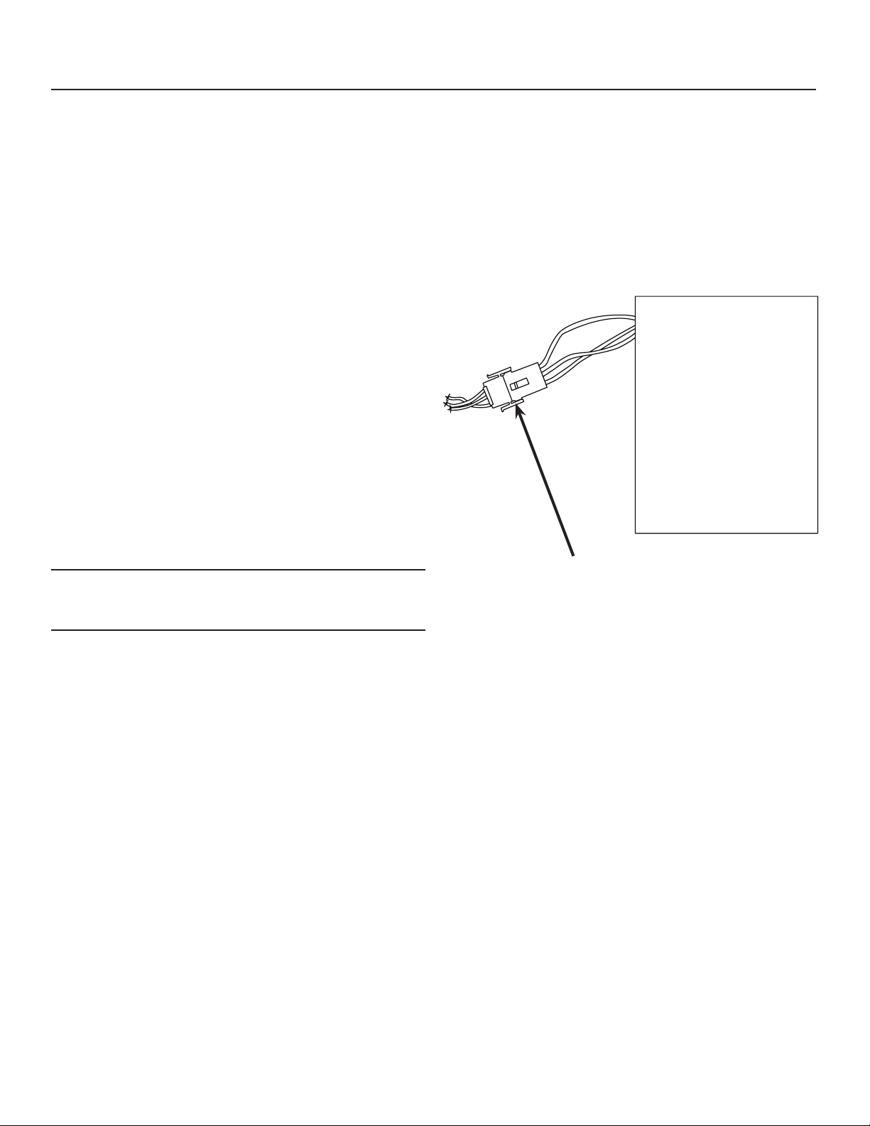
Communication Cable
Plug the interconnecting communication cable into the
harness at the back of the head unit’s electrical box.
Connect Communication Cable Here
July 2013
Page 14
Page 16
EH330, EH430 and ECC Condensing Unit
Remote Low Side Cuber Service Manual
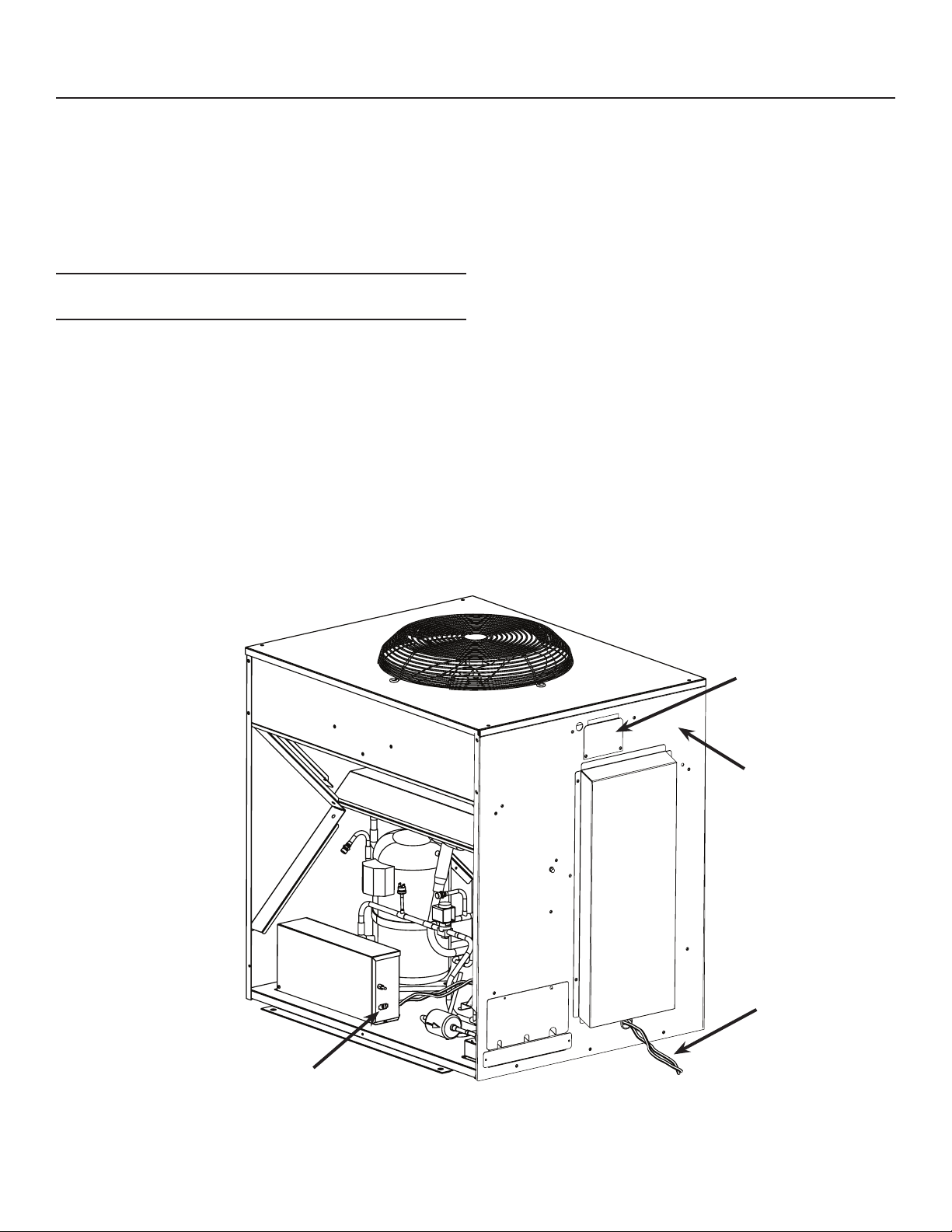
Condensing Unit Electrical
Route interconnecting control wire through proper
hole in side of CU unit and plug into the connection on
the side of the control box.
Route power conduit (liquid tight) and wires to the
hole in the side of the CU unit. Connect to wire leads
or terminal strip, if used, with the proper type of
connector.
Note: The power supply wires must be the correct
size and type per the National Electric Code.
Locate the nameplate on the CU unit for the Voltage,
Phase, Minimum Circuit Ampacity and Maximum Fuse
Size. Either fuses or HACR type circuit breakers may
be used.
Follow all Local, State and National Codes.
Three Phase Notice: Check voltage between legs
at contactor. If there is a “wild leg” in the three phase
power supply move supply wires so the higher voltage
is on L3 of the contactor, which connects to the
compressor motor only.
Connect Cable Here
Electrical Junction Box
Dataplate Location
Communication
Cable
July 2013
Page 15
Page 17
EH330, EH430 and ECC Condensing Unit
Remote Low Side Cuber Service Manual
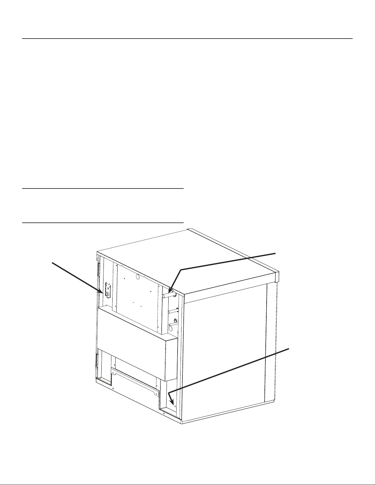
Water and Drain
All models require connection to cold, potable water.
A hand actuated valve within sight of the machine
is required. There is a single 3/8” FPT inlet water
connection.
Water Filters
Install a new cartridge if the lters were used with a
prior machine.
All models require drain tubing to be attached to them.
There is a single ¾” FPT drain tting in the back of the
cabinet.
Install new tubing when replacing a prior ice machine,
as the tubing will have been sized for the old model
and might not be correct for this one.
1. Connect water supply to water inlet tting.
Note: This NSF listed model has a 1" anti-back ow
air gap between the potable water inlet tube end and
the highest possible reservoir water level, no back
ow device is required.
2. Connect drain tubing to drain tting.
3. Route the drain tubing to building drain. Follow
local codes for drain air gap. Use rigid drain tubes
and route them separately – do not Tee into the bin’s
drain.
Vent the reservoir drain. A vertical vent at the back
of the drain, extended about 8 – 10” will allow the
gravity drain to empty and also keep any surges
during draining from discharging water.
Horizontal runs of drain tubing need a ¼” per fall per
foot of run for proper draining.
Follow all applicable codes.
Water
Inlet
Refrigeration
Connections
Reservoir Drain
Fitting
July 2013
Page 16
Page 18
EH330, EH430 and ECC Condensing Unit
Remote Low Side Cuber Service Manual
Connect Refrigeration
Requires brazing, steps must be performed by an
EPA certied type II or higher technician.
At Head:
1. Remove protective plugs from all three
connections and vent the nitrogen from the ice
machine.
2. Route the each of the three tubes to its
connection.
3. Remove the top panel and attach a refrigeration
hose with depressor to the 1/2 inch ID vapor line
access valve so the valve is OPEN. This is a vent
for nitrogen purging.
4. Clean tubing ends and position into the couplings.
At Condensing Unit
1. Conrm connection
valves are fully
closed.
At Head
1. With nitrogen owing from condensing unit, braze
the liquid, vapor and suction line connections.
2. Remove refrigeration hose from head. Be sure
valve cap is on tight.
At Condensing Unit
1. Remove nitrogen supply.
2. Return valve cores to access valves.
3. Connect vacuum pump to all three access valves
and evacuate the tubing and head to at least a
300 micron level.
4. Remove vacuum pump and add R-404A vapor to
all three tubes to provide a positive pressure.
5. Leak check the braze connections and repair any
leaks.
6. Open all three valves to full open.
2. Remove protective
plugs from all three
connections.
3. Remove caps from access valve connections.
4. Remove cores from access valves.
5. Connect refrigeration hoses to access valves.
6. Connect dry nitrogen source to liquid line
connection and vapor line connection.
7. Shorten tubing to correct length, clean ends and
insert them into valve stubs.
Note: Be sure tube and stubs are round, dress with
swage tool if needed.
8. Add heat sink material to ball valve body.
9. Open nitrogen and ow 1 psi nitrogen into liquid
line and vapor line tubes and braze the liquid
line, vapor line and suction line tubes to the valve
stubs.
Valves Closed
Note: The full refrigerant charge is contained in the
receiver of the condensing unit.
Refrigeration Connections
July 2013
Page 17
Page 19

EH330, EH430 and ECC Condensing Unit
Remote Low Side Cuber Service Manual
Complete the Installation
After the utilities and refrigeration connections have
been made, secure the unit to the dispenser or bin
top.
Secure ice making section to dispenser or bin
adapter.
Use strap/clips to secure unit. On some bins or
dispensers it may be necessary to drill small holes
and use eld supplied sheet metal screws to secure
the ice making head to that bin, dispenser or adapter.
If the ice maker & bin or dispenser is not yet in its nal
position gently move it there.
Note: The refrigerant lines above the machine must
be able to move freely while the machine is being
moved into position.
Final Check List Before Initial Start Up
1. Conrm that the ice making section is installed
indoors in a controlled environment.
2. Conrm that all packing materials have been
removed from all products.
3. Conrm that the ice making section is level.
4. Conrm that all the refrigerant connections have
been made and checked for leaks.
5. Conrm that the proper power supply has been
turned on to the condensing unit.
6. Conrm that cold, potable water has been supplied
to the ice making section and checked for leaks.
7. Conrm that the water supply is adequate.
8. Conrm that there is adequate water pressure and
that any water lters have been checked to conrm
that the cartridges do not need changing.
9. Conrm that the proper size drain tubing has been
installed and properly routed.
10. Conrm that the ice making section has been
connected to the proper power supply.
11. Conrm that the interconnecting wire has been
routed and connected between the ice making section
and the condensing unit.
July 2013
Page 18
Page 20

EH330, EH430 and ECC Condensing Unit
Remote Low Side Cuber Service Manual
Reference for Start Up: Controller Operation
he controller and remote switch panel have four
indicator lights and the On and Off buttons.
Lower light and switch panel
Indicator Lights
• Power - on when there is power to the controller
• Status - on in ice making mode
• Water - on and blinking when there is no water
• De-scale & Sanitize - on when it is time to clean
the machine
Component indicator lights
• Fan - not used on this model
• Water Pump - on when the pump is
• Purge Valve - on when the purge valve is
• Water Solenoid - on when the inlet water solenoid
valve is
• Hot Gas - on when the vapor inlet valve and
harvest assist solenoid / mechanism have power
• Compressor - on when the compressor contactor
is energized
• Ready to Harvest - on when the ice thickness
sensor has water touching it
• Sump Empty - on when there is no water touching
the mid-length probe
• Sump Full - on when water is touching the
shortest probe
• SW2 - on when the curtain is open
• SW1 - on when the curtain is open
Cycle Denitions:
Freeze: The refrigeration system is operating to
remove heat from the evaporators. The compressor,
fan motor, and water pump are on.
Code Display
• Displays status and diagnostic codes
Push Buttons
• On
• Off
• Manual Harvest
• Clean
Harvest: The refrigeration system and water system
are operating to harvest the ice and rinse the
reservoir. The compressor is on for the full cycle, the
pump is on until the purge valve closes.
The inlet water valve opens and rells the reservoir.
The vapor and condenser by-pass valves are open
during the entire harvest cycle, as are the harvest
assist mechanisms.
May 2015
Page 19
Page 21

EH330, EH430 and ECC Condensing Unit
Remote Low Side Cuber Service Manual
Initial Start Up
Pre Start
A soak-out period of four hours is optional for this
system. If desired, powering the compressor unit
for four hours prior to start up allows the crankcase
heater to warm up the oil in the compressor.
Start Up
1. Connect power to the condensing unit and move
its toggle switch to Run or On.
2. Open the water supply valve.
3. Remove the head’s front panel. Check for any
packing or wires rubbing moving parts. Note
location of control board in upper left corner of the
machine’s front.
4. Remove any tape securing curtain to evaporator.
5. Switch on the electrical power to the EH head.
Observe that some of the control’s indicator lights
glow and its display shows O.
position.
Note: Moving a curtain during the Freeze cycle has no
affect on control function, but will cause water to ow
into the cube chute. When enough ice has frozen, the
Ready for Harvest indicator light will be on steady.
After it’s been on steady for a few seconds Harvest
will begin.
The display shows an H. The vapor valve in the EH
opens, and the harvest assist mechanism activates.
In the CU the condenser bypass valve opens and
the receiver inlet valve closes. In the EH, the purge
valve opens to drain some water, when it does the
inlet water valve opens to rell the reservoir. After a
few seconds the purge valve closes but the inlet water
valve continues to ll the reservoir. Harvest continues
until the ice is released as a unit and forces the
curtain to open.
When the curtain opens it signals the controller that
harvest is complete, and it returns the unit to a freeze
cycle.
6. Locate lower light and switch panel. Push and
release the ON button on that panel. The code
display will begin to blink F.
The purge valve opens, the water pump starts and the
inlet water valve opens to add water to the reservoir.
In a few seconds the purge valve closes and the
water pump stops. Water will ow into the machine
until the reservoir is full. The vapor valves and harvest
assist devices will activate, then the compressor and
water pump will start. The F will be on steady.
Note: Because the condensing unit is external to the
ice making section, no visible signs of operation will
be noticeable until the water begins to cool and frost
forms on the evaporator tubing.
7. Go to the condensing unit and conrm that the
compressor and fan motor are operating. Warm
air will be discharged from the condenser.
Observe the Ready for Harvest indicator light. It may
blink early in the cycle, that is normal. The control will
ignore that signal for the rst 6 minutes of freeze.
8. Check the ice harvested for proper bridge
thickness. The ice bridge is factory set at 1/8 inch.
If needed, adjust bridge thickness. Do NOT make
it too thin.
9. Return the front panel to its normal position and
secure it to the machine.
10. Instruct the user in the operation of the machine
and its maintenance requirements.
11. Fill out and mail the warranty registration form or
register it on line at www.scotsman-ice.com.
During the Freeze cycle move the curtains and
observe that the SW1 or SW2 light on the control
board blinks On when the curtain moves away from
the evaporator and Off when returned to its normal
May 2015
Page 20
Page 22

EH330, EH430 and ECC Condensing Unit
Remote Low Side Cuber Service Manual
Ice Thickness and Water Purge Adjustment
Bridge Thickness - For the Service Tech Only
1. Push and hold Off till the machine stops.
2. Remove evaporator cover.
3. Remove left curtain.
4. Use a hex wrench and rotate the bridge thickness
adjustment screw in 1/16 turn increments CW to
increase bridge thickness.
5. Rotate CCW to decrease bridge thickness.
Caution: Do not make the bridge too thin or the
machine will not harvest properly. Bridge thickness
adjustments are not covered by warranty.
6. Return curtain and evaporator cover to their
normal positions.
7. Push and release the On button. Check next
harvest of ice. Repeat steps 1-6 if needed.
Water Purge Setting
TOO BIG
Small Depression
1/8 to 3/16”
Bridge
JUST RIGHT
TOO SMALL
The water purge is factory set to the automatic
position, suitable for most water conditions. The
setting can be changed to one of 5 manual settings or
left on automatic.
Setting Water Type
1 Minimum - RO water or equivalent
2 Moderate - Low TDS, non RO
3 Standard - Use with typical water
4 Heavy - High TDS
5 Maximum - Very high TDS
A Automatic - Factory setting
To set:
1. Switch the machine OFF by holding the Off button
in until a number or the letter A shows on the
display.
2. Press and release the On button repeatedly until
the number on the display corresponds to the
desired setting.
Adjustment
Screw
3. Press and release the Off switch again to return to
the normal control state.
July 2013
Page 21
Page 23

EH330, EH430 and ECC Condensing Unit
Remote Low Side Cuber Service Manual
Cleaning, Sanitation and Maintenance -C Series
This ice system requires three types of maintenance:
• Remove the build up of mineral scale from the ice
machine’s water system and sensors.
• Sanitize the ice machine’s water system and the
ice storage bin or dispenser.
• Clean the remote air cooled condenser.
It is the User’s responsibility to keep the ice machine and ice storage bin in a sanitary condition. Without
human intervention, sanitation will not be maintained. Ice machines also require occasional cleaning of their
water systems with a specically designed chemical. This chemical dissolves mineral build up that forms during
the ice making process.
Sanitize the ice storage bin as frequently as local health codes require, and every time the ice machine is
cleaned and sanitized.
The ice machine’s water system should be cleaned
and sanitized a minimum of twice per year.
yellow Clean light will be on continuously and the
machine will drain and rell the reservoir to ush
out the ice machine cleaner and residue.
1. Remove the front panel.
9. Allow the drain and rell process to continue for at
2. Remove the evaporator cover.
3. If the machine is operating, push and release the
Harvest button. When the machine completes the
least 20 minutes.
10. Push and release the Off button. The clean cycle
will stop and the display will show O.
Harvest cycle it will stop. If the bin is full (b shows
in display) push and release the Off button.
Note: If unit has not been de-scaled for an extended
period of time and signicant mineral scale remains,
4. Remove all ice from the storage bin or dispenser.
repeat steps 5 - 10.
5. Push and release the Clean button. The yellow
Clean light will blink and the display will show
steady C. The machine will drain the reservoir
and rell it. Go onto the next step when the purge
valve light goes out.
6. Pour 24 ounces of Scotsman Clear 1 nickel safe
scale remover into the reservoir.
Ice machine scale remover
contains acids. Acids can
cause burns.
If concentrated cleaner comes
in contact with skin, ush with
water. If swallowed, do NOT
induce vomiting. Give large
amounts of water or milk. Call
Physician immediately. Keep
out of the reach of children.
7. Allow the ice machine cleaner / scale remover
to circulate in the water system for at least 10
minutes.
8. Push and release the Clean button again. The
11. Mix a cleaning solution of 1 oz of ice machine
cleaner to 12 ounces of water.
12. Remove curtains from unit.
13. Locate ice thickness sensor. Squeeze mounting
legs together to release sensor.
14. Remove water distributors from ice machine by
disconnecting hoses, squeezing the retaining
snaps together and pulling each distributor
forward until it stops. Lift up to remove. Inspect
distributor for restricted orice holes. Be sure all
holes are full open.
15. Locate water level sensor. Squeeze catches
together and pull up to remove sensor. Separate
probes from housing and wash all surfaces with
ice machine scale remover solution. Return
probes to holder.
16. Wash the metal surfaces of the ice thickness
sensor and the adjustment screw with ice machine
cleaner solution. Also wash the water distributor,
water level sensor probes and curtain with the ice
machine cleaner solution.
July 2013
Page 22
Page 24

EH330, EH430 and ECC Condensing Unit
Remote Low Side Cuber Service Manual
Step 15.
Release
probes by
pushing in on
white buttons
and pulling
probe down
out of holder.
17. Create a solution of sanitizer. Mix 8 ounces of
NuCalgon IMS II and 5 gallons of 105-115 degree
F. potable water to create a 200 ppm active
quaternary solution.
cleaned occasionally to keep the system operating at
high efciency.
Remove any large debris from the outside of the coil.
Vacuum accumulated dust.
Wash out the coils with water.
Caution: Do NOT use excessive water pressure as
that will bend the ns.
If the coils have become coated with grease, a coil
cleaner will have to be used to wash the coils.
Disconnect power to the condensing unit and remove
the condenser top.
18. Thoroughly wash all surfaces of the ice thickness
sensor, water level sensor, curtain and water
distributor with the sanitizer solution.
19. Thoroughly wash all interior surfaces of the
freezing compartment, including evaporator
frames, evaporator cover and the part of the top
panel covering the freezing compartment with the
sanitizer solution.
20. Return water level sensor, ice thickness sensor,
water distributors and curtains to their normal
positions. Be sure hose is reattached to water
distributors. Be sure ice thickness sensor it dry.
21. Push and hold the clean button to drain the
reservoir. Push and release the clean button again
and when the purge valve indicator light goes out,
immediately pour the remaining cleaning solution
into the reservoir.
22. Circulate the sanitizer solution for 10 minutes,
then push and release the Clean button.
Inspect the fan blade to be sure it is not cracked and
is clean.
Return the condenser top to its original position and
reconnect the power supply.
23. Allow the water system to be ushed of sanitizer
for at least 20 minutes, then push and release the
Off button.
24. Return the evaporator cover and front panel to
their normal position and secure with the original
fasteners.
25. Push and release the On button to resume ice
making.
Other Maintenance
The remote air cooled condenser coil must be
July 2013
Page 23
Page 25

EH330, EH430 and ECC Condensing Unit
Remote Low Side Cuber Service Manual
Cleaning, Sanitation and Maintenance - D Series
This ice system requires three types of maintenance:
• Remove the build up of mineral scale from the ice
machine’s water system and sensors.
• Sanitize the ice machine’s water system and the
ice storage bin or dispenser.
• Clean the remote air cooled condenser.
It is the User’s responsibility to keep the ice machine and ice storage bin in a sanitary condition. Without
human intervention, sanitation will not be maintained. Ice machines also require occasional cleaning of their
water systems with a specically designed chemical. This chemical dissolves mineral build up that forms during
the ice making process.
Sanitize the ice storage bin as frequently as local health codes require, and every time the ice machine is
cleaned and sanitized.
The ice machine’s water system should be cleaned
and sanitized a minimum of twice per year.
Note: If unit has not been de-scaled for an extended
period of time and signicant mineral scale remains,
repeat steps 6 - 8.
1. Remove the front panel.
8. Remove curtain from unit.
2. Remove the evaporator cover.
9. Locate ice thickness sensor. Squeeze mounting
3. Remove all ice from the storage bin or dispenser.
4. Push and release the Clean button. The yellow
Clean light will blink and the display will show
C. The machine will harvest any ice, drain the
reservoir and begin to rell it.Remove all ice from
the storage bin or dispenser.
5. Observe code display, when it blinks the
characters “A d 1” immediately go to the next
step.Observe code display, when it blinks the
characters “A d 1” immediately go to the next step.
6. Pour 24 ounces of Scotsman Clear 1 ice machine
scale remover into the reservoir. The unit will
circulate the scale remover, then drain and ush
it. This will take 35 minutes, then the machine will
stop and the display will show O.
7. Mix a cleaning solution of 1 oz of ice machine
cleaner to 12 ounces of water.
legs together to release sensor.
10. Remove water distributor from ice machine by
disconnecting its hose, squeezing the retaining
snaps together and pushing the distributor to the
right as far as possible. Lift up to remove. Inspect
distributor for restricted orice holes. Be sure all
holes are full open..
11. Locate water level sensor. Squeeze
catches together and pull up to remove
sensor. Separate probes from housing and
wash all surfaces with ice machine scale
remover solution. Return probes to holder.
.
12. Wash the metal surfaces of the ice thickness
sensor and the adjustment screw with ice machine
cleaner solution. Also wash the water distributor,
water level sensor probes and curtain with the ice
Ice machine scale remover
contains acids. Acids can
cause burns.
If concentrated cleaner comes
in contact with skin, ush with
water. If swallowed, do NOT
induce vomiting. Give large
amounts of water or milk. Call
Physician immediately. Keep
out of the reach of children.
Step 13
Release
probes by
pushing in on
white buttons
and pulling
probe down
out of holder.
May 2015
Page 24
Page 26

EH330, EH430 and ECC Condensing Unit
Remote Low Side Cuber Service Manual
Inspect Orifice Holes
machine cleaner solution.
13. Create a solution of sanitizer. Mix 8 ounces of
NuCalgon IMS II and 5 gallons of 105-115 degree
F. potable water to create a 200 ppm active
quaternary solution.
making.
Other Maintenance
The remote air cooled condenser coil must be
cleaned occasionally to keep the system operating at
high efciency.
Remove any large debris from the outside of the coil.
Vacuum accumulated dust.
Wash out the coils with water.
Caution: Do NOT use excessive water pressure as
that will bend the ns.
If the coils have become coated with grease, a coil
cleaner will have to be used to wash the coils.
Disconnect power to the condensing unit and remove
the condenser top.
Inspect the fan blade to be sure it is not cracked and
is clean.
14. Thoroughly wash all surfaces of the ice thickness
sensor, water level sensor, curtain and water
distributor with the sanitizer solution.
15. Wash all interior surfaces of the freezing
compartment, including evaporator cover and right
side panel liner with the sanitizer solution.
16. Return water level sensor, ice thickness sensor,
water distributor and curtain to their normal
positions. Be sure water level sensor and ice
thickness sensor are completely dry.
17. Push and release the Clean button. The yellow
Clean light will blink and the display will show C.
The machine will go through a harvest cycle, drain
the reservoir and begin to rell it.
18. Observe code display, when it blinks the
characters “Ad1” immediately go to the next step.
19. Pour the sanitizing solution into the reservoir until
it is full. The unit will circulate the sanitizer, then
drain and ush it. This will take 35 minutes, then
the machine will stop and the display will show O.
Return the condenser top to its original position and
reconnect the power supply.
20. Return the evaporator cover and front panel to
their normal position and secure with the original
fasteners.
21. Push and release the On button to resume ice
May 2015
Page 25
Page 27

EH330, EH430 and ECC Condensing Unit
Remote Low Side Cuber Service Manual
Critical Maintenance - Spillway
The freeze cycle on a Prodigy cuber is controlled by an ice thickness sensor positioned in front of the ice
making surface. It is triggered by water contact. Normally water only contacts the sensor when the ice is at the
proper size. However, irregular water ow can cause premature contact resulting in a short freeze cycle, small
bridge, long harvest and even a shut down on short freeze (code 8).
The primary procedure for correcting poor water ow is to scrub the spillway surface.
1. Shut machine off.
2. Remove right side panel liner and panel.
3. Disconnect ice thickness sensor from its bracket and move out of the way.
4. Scrub 4 to 6 strokes across the normal ow of water. A clean nylon scrubbing pad is the recommended tool.
Spillway Surface
5. Reassemble all components and retest operation.
Other short freeze causes include:
• Mis-adjustment of ice thickness sensor.
• Broken, bent, or dismounted ice thickness sensor.
• Sagging water distributor mounting bracket. See Service Bulletin PS-9-2012.
May 2015
Page 26
Page 28

EH330, EH430 and ECC Condensing Unit
Remote Low Side Cuber Service Manual
Critical Maintenance - Ice Thickness Sensor
The freeze cycle on a Prodigy cuber is controlled by an ice thickness sensor positioned in front of the ice
making surface. It is triggered by water contact. Water contacts the sensor when the ice is at the proper size.
During use the Ice Thickness Sensor will become coated with mineral scale from the water, which if left
untreated can cause changes in bridge thickness.
To correct, the Ice Thickness Sensor must have the mineral scale removed.
1. Remove the ice thickness sensor from the water distributor bracket.
2. Separate the metal sensor from the plastic insulator-bracket.
3. Wipe the sensor with diluted ice machine scale remover,
4. Scrub the white or dark gray plastic insulator-bracket with diluted ice machine scale remover and remove
all traces of mineral build up
5. Wipe the wire to the bulkhead with diluted ice machine scale remover.
6. Wash all ice thickness sensor parts off with clean water.
7. Blow air thru metal sensor and insulator-bracket to dry them.
8. Reassemble and remount to water distributor bracket.
Insulator-Bracket
Separate these two
parts.
Clean them with
diluted ice machine
scale remover.
Rinse with clean
water.
Blow dry and
reassemble.
May 2015
Page 27
Metal Sensor
Page 29

EH330, EH430 and ECC Condensing Unit
Remote Low Side Cuber Service Manual
Critical Maintenance - Water Level Sensor
1. Remove Water Level Sensor
3. Pull down, then lift up to remove probe. 4. Clean all dirty and scale from the housing.
2. Release probes by pushing pints in.
5. Clean entire probe, be sure circled area is clean.
May 2015
Page 28
Page 30

EH330, EH430 and ECC Condensing Unit
Remote Low Side Cuber Service Manual
Operational Characteristics 1200 lb system (ECC1200/EH330)
Cycle Times @ Condenser Temp/Cabinet Temp/Water Temp in degrees F.
70/70/50 90/90/70 120/110/100
Freeze 9 to 11 minutes 12 to 13 minutes 17 to 19 minutes
Harvest 1 to 1.5 minutes 1 minute .5 to 1 minute
System Pressures @ Condenser Temp/Cabinet Temp/Water Temp in degrees F
70/70/50 90/90/70 120/110/100
Suction at head, end of Freeze 29 to 31 PSIG 28 to 32 PSIG 36 to 38 PSIG
Suction at head, Harvest - Peak 92 to 98 PSIG 165 PSIG 170 PSIG
Discharge at Condensing Unit:
Freeze - 5 minutes in
230 to 250 PSIG 250 to 285 PSIG 350 PSIG
Operational Characteristics 1400 lb system (ECC1410/EH430)
Cycle Times @ Condenser Temp/Cabinet Temp/Water Temp in degrees F.
70/70/50 90/90/70 120/110/100
Freeze 14 minutes 16 to 17 minutes 25 to 27 minutes
Harvest 1.5 minutes 1 to 1.5 minutes .5 to 1 minute
System Pressures @ Condenser Temp/Cabinet Temp/Water Temp in degrees F
70/70/50 90/90/70 120/110/100
Suction at head, end of Freeze 35 to 37 PSIG 35 PSIG 41 to 44 PSIG
Suction at head, Harvest - Peak 85 to 105 PSIG 100 to 120 PSIG 120 to 130 PSIG
Discharge at Condensing Unit:
Freeze - 5 minutes in
220 to 230 PSIG 260 to 270 PSIG 350 to 380 PSIG
Below information applies to both size systems:
Headmaster maintains a minimum discharge pressure during freeze of 217 PSIG + 25, -15 PSIG.
CPR Valve Setting: 55 - 60 PSIG.
Note: CPR allows a maximum low side pressure at the compressor. Maximum only occurs during harvest.
Refrigerant Charge
• 1200 - 224 oz.; 1400 - 224 oz,
Compressor Amps 1200
• Single Phase - 10 to 14
Compressor Amps, 1400
• Single Phase - 8 to 12
• Three Phase - 6 to 10
Batch Weight: 1200 - 10 lb
Batch Weight - 1400 - 14 -15 lb
Discharge Pressure Cut Out Switch
• Cuts Out at: 450 PSIG Resets at: 350 PSIG
July 2013
Page 29
Page 31

EH330, EH430 and ECC Condensing Unit
Remote Low Side Cuber Service Manual
Operational Characteristics 1800 lb system (ECC1800/EH430)
Cycle Times @ Condenser Temp/Cabinet Temp/Water Temp in degrees F.
70/70/50 90/90/70 120/110/100
Freeze 10 to 12 minutes 12 to 14 minutes 17 to 19 minutes
Harvest 1.5 to 2 minutes 1.5 minutes 1 minute
System Pressures @ Condenser Temp/Cabinet Temp/Water Temp in degrees F
70/70/50 90/90/70 120/110/100
Suction at head, end of Freeze 24 to 25 PSIG 29 to 32 PSIG 32 to 35 PSIG
Suction at head, Harvest - Peak 80 to 100 PSIG 90 to 110 PSIG 140 to 160 PSIG
Discharge at Condensing Unit:
Freeze - 5 minutes in
Headmaster maintains a minimum discharge pressure during freeze of 217 PSIG + 25, -15 PSIG.
CPR Valve Setting: 55 - 60 PSIG.
Note: CPR allows a maximum low side pressure at the compressor. Maximum only occurs during harvest.
240 to 260 PSIG 250 to 270 PSIG 370 to 380 PSIG
Refrigerant Charge
• 1800 - 232 oz
Compressor Amps, 1800
• Three Phase - 10 to 14
Batch Weight: 14 - 15 lb
Discharge Pressure Cut Out Switch
• Cuts Out at: 450 PSIG Resets at: 350 PSIG
July 2013
Page 30
Page 32

EH330, EH430 and ECC Condensing Unit
Remote Low Side Cuber Service Manual
Ice Thickness and Water Purge Adjustment
Bridge Thickness - For the Service Tech Only
1. Push and hold Off till the machine stops.
2. Remove evaporator cover.
3. Remove curtain.
4. Use a hex wrench and rotate the bridge thickness
adjustment screw in 1/16 turn increments CW to
increase bridge thickness.
5. Rotate CCW to decrease bridge thickness.
Caution: Do not make the bridge too thin or the
machine will not harvest properly. Bridge thickness
adjustments are not covered by warranty.
6. Return curtain and evaporator cover to their
normal positions.
7. Push and release the On button. Check next
harvest of ice. Repeat steps 1-6 if needed.
1/8 to 3/16”
Bridge
ice Bridge Thickness
Water Purge Setting
The water purge is factory set to the automatic
position, suitable for most water conditions. The
setting can be changed to one of 5 manual settings or
left on automatic.
Setting Water Type
1 Minimum - RO water or equivalent
2 Moderate - Low TDS, non RO
3 Standard - Use with typical water
4 Heavy - High TDS
5 Maximum - Very high TDS
A Automatic - Factory setting
To set:
1. Switch the machine OFF by holding the Off button
in until a number or the letter A shows on the
display.
2. Press and release the On button repeatedly until
the number on the display corresponds to the
desired setting.
Adjustment
Screw
Bridge Thickness Adjustment Mechanism
3. Press and release the Off switch again to return to
the normal control state.
May 2015
Page 31
Page 33

EH330, EH430 and ECC Condensing Unit
Remote Low Side Cuber Service Manual
Controller Information
Machine Indicator Lights
• Power
• Status
• Water
• Clean
Code Display
Main codes - automatically displayed
F Freeze Cycle
F ashes Freeze Cycle is Pending
H Harvest Cycle
H ashes Manual Harvest
b Bin is Full
C Clean Cycle
L Board Locked
d Test Mode
O Off
E Self Test Failed
1 ashes Max Freeze - Retrying
1 Max Freeze Time Shut Down
2 ashes Max Harvest - Retrying
2 Max Harvest Time Shut Down
3 Slow Water Fill
4 High Discharge Temp
5 Sump Temp Sensor Failure
7 Discharge Temp Sensor Failure
8 ashes Short Freeze - Retrying
8 Short Freeze - Thin ice
Setting Codes - requires push button sequence for access
Water Purge Settings
A, 1, 2, 3, 4, 5
De-scale Interval Settings
6, 5, 3, 3
July 2013
Page 32
Page 34

EH330, EH430 and ECC Condensing Unit
Remote Low Side Cuber Service Manual
Operation
Once started, the ice machine will automatically make
ice until the bin or dispenser is full of ice. When ice
level drops, the ice machine will resume making ice.
Caution: Do not place anything on top of the ice
machine, including the ice scoop. Debris and moisture
from objects on top of the machine can work their way
into the cabinet and cause serious damage. Damage
caused by foreign material is not covered by warranty.
There are four indicator lights at the front of the
machine that provide information on the condition of
the machine.
Indicator Lights:
• Power
• Status
• Water
• De-scale & Sanitize
Indicator Lights & Their Meanings
Power Status Water De-Scale & Sanitize
Steady Green Normal Normal – bin full or
making ice
Blinking Green Self Test Failure Switching on or off - Blinking Red - Diagnostic
shutdown or,
if making ice,
temperature sensor
failure
Yellow - - - Time to de-scale
Blinking Yellow - - - In Cleaning mode
Light off No power Switched off Normal Normal
If the Water light is on, the machine has sensed a
lack of water. Check the water supply to the machine.
The water could have been shut off or the water lter
cartridges might need to be changed.
If the De-Scale light is on, the machine has
determined that it needs to be cleaned. Contact an
authorized Scotsman service agent and have the
machine cleaned, de-scaled and sanitized.
- -
Lack of water -
and sanitize
July 2013
Page 33
Page 35

EH330, EH430 and ECC Condensing Unit
Remote Low Side Cuber Service Manual
System Operation:
This section is intended for the technician. Understanding it is not necessary for the normal operation and
maintenance of this ice making system.
Major Components:
Ice making section sub-system:
• Controller,
• Water Level Sensor,
• Transformer,
• Evaporators,
• Expansion Valves
• Vapor Inlet Valves
• Water Pump,
• Inlet Water Valve
• Purge Valve.
• Harvest Assist Solenoid
Condensing Unit
• Compressor,
• Contactor,
• Condenser Bypass Valve,
• Liquid Inlet Valve,
• Receiver,
• Accumulator,
• CPR Valve,
• Headmaster.
• Coils
• Fan Motor
Freeze:
In the air cooled condensing unit sub-system the compressor is on, the condenser by-pass valve is closed, the
fan motor is rotating the fan blade.
Harvest:
During harvest the compressor and fan motor continue to operate. The vapor inlet, condenser bypass, receiver
inlet solenoid (normally open) and harvest assist solenoids are energized.
Ice releases and falls into the bin or dispenser.
July 2013
Page 34
Page 36

EH330, EH430 and ECC Condensing Unit
Remote Low Side Cuber Service Manual
Refrigeration Details:
The compressor provides the force that circulates
refrigerant in the refrigeration system. During freeze,
when the vapor inlet and condenser by pass valves
are closed, discharge gas ows from the compressor
into the condenser, where its heat is discharged into
the air stream. Liquid refrigerant ows out of the
condenser and through the normally open liquid line
outlet valve on its way to the receiver inlet. Under low
ambient/low pressure conditions, the headmaster
valve closes the liquid outlet of the condenser and
opens a bypass route to direct refrigerant gas to the
receiver inlet until discharge pressure builds back up
to the headmaster’s set point.
From the receiver liquid outlet, liquid refrigerant
ows into the liquid line and into the ice making
section. At the ice making section, the refrigerant
ows into the expansion valves where a pressure
change takes place. The liquid refrigerant moves
from the expansion valves into a low-pressure area
(the evaporators) where it can rapidly evaporate
and absorb heat. Heat is absorbed from the copper
evaporator tubing, attached copper and
the water owing over the evaporator.
The low-pressure refrigerant gas
Condenser
then ows into the suction line, which
carries it back to the condensing unit,
where it enters the accumulator. In the
accumulator most of any liquid carried
with the suction gas is separated and
only vapor ows out of the accumulator
through the CPR valve and to the
compressor where the cycle continues.
Liquid
Inlet
(NO)
During harvest discharge gas ows
through the open condenser by pass
valve into the vapor line. Power is also
applied to the coil of the liquid inlet
valve, closing it. At the same time, in
the ice making section, the vapor inlet
valves open.
The low-pressure refrigerant then ows out of the
evaporator and into the suction line. The suction line
brings the refrigerant, now consisting of a vaporliquid combination, to the accumulator. From the
accumulator the vapor-liquid combination (now
more vapor than liquid) goes to the Crankcase
Pressure Regulator valve which limits the amount of
dome pressure in the compressor, where the cycle
continues.
Head Pressure
Valve
Bypass
Valve
Accumulator
CPR Valve
Interconnecting
Tubing
Ice Making Head
Discharge gas, combined with some
vapor from the receiver’s outlet,
then ows through the vapor line
to the evaporator inlet. The gasvapor combination, when entering
the relatively cold evaporator,
condenses, transferring latent heat
to the evaporator, which warms it.
Ice releases and falls into the bin.
Receiver
Vapor Valve
Ball Valves
July 2013
Page 35
Page 37

EH330, EH430 and ECC Condensing Unit
Remote Low Side Cuber Service Manual
Freeze Cycle Sequence of Operation
This sequence begins with a restart after the unit has
shut off with the bin full. Ice has been consumed,
causing the ice sensors to become un-blocked.
1. The controller (four minutes has to have passed
since the machine shut off on bin full for the machine
to restart)
2. The purge valve is opened and the pump started.
3. After the purge valve closes the inlet water valve
opens and lls the reservoir.
Note: If the water reservoir does not ll within the time
period expected the controller will shut off and switch
on the water indicator light. It will re-try to ll the
reservoir in 20 minutes. If successful the freeze cycle
will continue.
4. The compressor and fan motor start and the
freezing process begins.
Note: The controller is connected to two external
relays in the EH head, one for the condensing
unit’s compressor contactor and the other for the
its solenoid valves. A separate 24 volt transformer
is in the condensing unit supplying power to the
contacts of these two line voltage relays through the
interconnecting wire.
5. The controller will shut the water pump off for a
few seconds when the reservoir’s water temperature
reaches a pre-set point.
6. The freeze cycle continues until water makes
continuous contact with the ice thickness sensor. That
signals the controller to terminate the freeze cycle and
begin the harvest cycle. The Ready to Harvest light
will be ON.
July 2013
Page 36
Page 38

EH330, EH430 and ECC Condensing Unit
Remote Low Side Cuber Service Manual
Harvest Cycle Sequence of Operation
When harvest begins, the controller connects
power to the external relay for the condensing unit's
solenoids.
It also connects power to the vapor inlet solenoid
valves in the cabinet of the EH head.
The vapor inlet solenoid valves and the condenser
bypass valve open. The receiver inlet solenoid valve
closes. Vapor ows from the condensing unit to the
EH head evaporator inlets.
The water pump and purge valve will be on for a
period of time during the rst part of harvest to purge
the water reservoir of a portion of the water.
The inlet water solenoid valve opens to ll the
reservoir when the water level sensor indicates an
empty sump. It continues to ll when the pump and
purge valve have shut off and will stop lling when the
water level sensor senses a full sump.
Harvest will continue until both curtains have opened.
The curtain switch, attached to the edge of each
curtain, will sense the curtain opening.
If the curtains both close, harvest will terminate and
the freeze cycle will resume.
If one or both of the curtains remains open for 30
seconds, the machine will shut down
July 2013
Page 37
Page 39

EH330, EH430 and ECC Condensing Unit
Remote Low Side Cuber Service Manual
Control Safeties
Max freeze time – 45 minutes
When exceeded, the controller will attempt another
freeze cycle. If the condition is exceeded again the
next cycle, the control will again attempt another
freeze cycle. If the freeze cycle exceeds the maximum
time in 3 consecutive cycles, the controller will shut
the machine off and it must be manually reset.
Min freeze time – 6 minutes
If the controller switches the machine into harvest
within 20 seconds of the minimum freeze time, the
controller will harvest for a preset time and does not
stop if the curtain switch opens. If this occurs again in
the next three cycles, the machine will shut down and
must be manually reset.
Max harvest time – 3.5 minutes
If the harvest cycle has continued for 3.5 minutes
without the curtain opening, the controller will shut the
machine off for 50 minutes and then restart. If there
is another the machine will shut the machine off for
another 50 minutes and then restart. If it fails a third
consecutive time the controller will shut the machine
down and must be manually reset.
Restarts
Power Interruption
The controller will automatically restart the ice
machine after adequate voltage has been restored.
• H blinks on code display
• Status indicator light blinks
• Reservoir is drained and relled
• Default harvest is initiated. The curtain switch
does not have to open to terminate harvest,
harvest will continue until the default harvest time
expires. Default harvest time is 3 minutes. The
machine will then return to a normal freeze cycle.
Water Interruption
The controller will attempt to ll the reservoir every
twenty minutes until it is successful.
• Time between resets – 50 minutes
• Number of automatic resets – 2
• Max water ll time – 5 minutes. Machine will
attempt a restart every 20 minutes.
• Max discharge temp – 250 degrees F.
• Time interval between cleanings – 6 months
power on time - adjustable in one month
increments, can be set at 6, 5, 4 or 3 months of
power up time.
• Manual harvest time – 3 minutes
• Pump down interval – remote only. 12 hours.
• Pump down is 30 seconds of compressor only on
time.
• Minimum compressor off time – 4 minutes
• Continuous Run Time Maximum Cycles - 25
July 2013
Page 38
Page 40

EH330, EH430 and ECC Condensing Unit
Remote Low Side Cuber Service Manual
Controller Operation
Control Button Use (from standby - status light off)
Set purge level, 1-5 (1 is minimum, 5 is maximum) or
Automatic:
• Hold off button in for 3 seconds. Release.
• Press and release the On button to cycle through
and select one of the ve purge settings or to use
the automatic setting.
Recall diagnostic code:
• Hold off button in for 3 seconds. Release.
• Press and release the Harvest button to cycle
through each of the last 10 error codes from most
recent to oldest.
Clear diagnostic code:
• Hold Clean and Harvest buttons in for 3 seconds
to clear all prior codes.
Reset control:
• Depress and release Off, then depress and
release On
Start Test Mode:
• Hold Off button in for 3 seconds. Release.
• Hold Clean button in for 3 seconds. Release.
Lock / Unlock control:
• Hold On button in for 3 seconds, keep holding
then press and release Off twice.
Empty reservoir:
• Hold Clean button in for 3 seconds. Release.
Pump and purge valve will be ON for 30 seconds.
Repeat as needed.
Test Mode:
• Depress Off for 3 seconds, release. Then depress
Clean for 3 seconds.
• The sump will ll the rst 30 seconds of the test.
If the sump is full it will overow into the bin. At 30
seconds the Water Inlet Valve will shut off and the
Water Pump will turn on. You will be able to see
and hear the water running over the plates. After
10 seconds the Purge and Vapor Inlet Valves will
turn on. Water will be purging from the machine.
After 10 more seconds the compressor will start. 5
seconds later the VIV will close. The compressor
will run for a total of 20 seconds. After which
everything will turn off for 5 seconds. After that
time the VIV will open and you’ll be able to hear
the hissing as the pressure is equalized. After 10
seconds all will be off and the output test will be
complete.
Change De-Scale Notication Interval
• Like the others, this feature is accessible only
from standby (Status Light Off).
• Press and hold harvest button for 3 seconds.
• This will allow control to enter Time to Clean
Adjustment State.
• Display current time to clean months on 7
segment display.
• Pressing clean button repeatedly will cycle
through one of 4 possible settings:
6 months (4380 hours) (default)
5 months (3650 hrs)
4 months (2920 hrs)
3 months (2190 hrs)
July 2013
Page 39
Page 41

EH330, EH430 and ECC Condensing Unit
Remote Low Side Cuber Service Manual
Service Diagnosis
Problem or Symptom Possible Cause Probable Correction
No ice No power to ice making section Restore power
No power to condensing unit Restore power
No lights on controller Check transformer
Unit manually switched off Push and release the On button, ask
user why it was shut off
Power to both sections, controller reset,
but condensing unit does not operate
No power to compressor contactor coil. Check toggle switch in condensing
No water to ice making section, controller
blinking water light
Ice making section has exceeded
maximum freeze time and controller has
shut down the system
Ice making section has exceeded maximum harvest time and shut down the
system
Condensing unit solenoids do not activate
during harvest
Interconnecting control wire disconnected, reconnect it
Low or high pressure cut outs open,
check system pressures
unit.
Check EH head compressor relay.
Restore water supply, check water
lters, reset controller
Check inlet water valve operation
Check water level sensor
Condenser coils may need cleaning
Check condenser fan blade and
motor
Check for excessive air intake tem-
peratures at condenser coil
Check compressor contactor
Check compressor and starting
components
Check water pump
Check purge valve for leak through
Check vapor inlet valve for leak
though
Check ice making section for lime
scale build up, clean as needed
Check condenser by pass valve
Check vapor inlet valve
Check headmaster
Check curtain switch
Check inlet water valve for leak
through
Check for obstruction in ice delivery
chute
Check solenoid relay in EH head
July 2013
Page 40
Page 42

EH330, EH430 and ECC Condensing Unit
Remote Low Side Cuber Service Manual
Service Diagnosis
Problem or Symptom Possible Cause Probable Correction
No ice No refrigeration, unit shut down,
maximum freeze time code displayed
Sump frozen Check for welded contactor
No water to ice making section Water level sensor working prop-
erly
Slow ice release during harvest Cubes are too large Check ice thickness sensor
Condenser by-pass valve does not
open
No ice sensed during harvest Ice sensing system failure Check curtain switch
No ice released to bin Ice outlet blocked - check for ob-
No ice released, vapor inlet valve
does not open
No ice, Code 1 Displayed Freeze cycle too long Check for false sump full indication
No ice, Code 2 Displayed Harvest cycle too long Check harvest assist
No ice, Code 3 Displayed Water supply inadequate Check water supply and inlet water
No ice, Code 8 Displayed Freeze cycle too short Check / clean ice thickness sensor
Check compressor, refrigerant
charge, and liquid inlet valve. Note
that if liquid inlet valve is not open,
compressor will pump down and
suction pressure will be very low.
Clean or replace sensor
Check for water leak
Check coil of valve
Check power to valve during har-
vest
struction
Check coil for continuity, if open
replace coil
Check for 24 volts to coil during
harvest, if none, check at relay in
EH head
Check low side pressure, if pressure does not rise during harvest,
and valve is electrically OK, replace vapor inlet valve
(See page 28)
Check condensing unit operation
Check refrigeration including head
pressure control valve, vapor
valve, bypass valve
Check water valve for leak thru
Check purge valve for leak thru
Check for false sump full
Check curtain switch
Check bypass and vapor valve
operation
solenoid valve
Clean water system (See page 27)
Scrub evaporator spillway (See
page 26)
May 2015
Page 41
Page 43

EH330, EH430 and ECC Condensing Unit
Remote Low Side Cuber Service Manual
Service Diagnosis
Problem or Symptom Possible Cause Probable Correction
Low capacity Dirty condenser Clean condenser
Poor ice formation - very cloudy
and misshapen
Whistling noise at condensing unit
during harvest
Air temperature intake to condenser very high
Water temperature intake to ice
making section very high
Ice broken up and stuck between
reservoir and curtain, happens
almost every cycle
Storage bin or dispenser not holding ice properly
High volume of drinks dispensed,
cold plate melting ice
Vapor inlet valve leaks through
slightly during the freeze cycle
Exceeding maximum freeze time,
compressor unit trips on high discharge temp
Dirty water system Clean the water distributor to re-
Low refrigerant charge. Add several pounds of refrigerant
By pass and liquid inlet valve coils
not getting power
Re-orient condenser to avoid hot
air intake
Check for hot water supply to ice
machine due to mal-functioning or
non-existent hot water check valve
at dishwashing sink
Ice thickness set too thin
Ice very uneven, check superheat
Slow harvest, check headmaster
Check drains for water ow from
ice machine (separate to correct)
or restriction
Suggest pre-cooler for water supply to cold plate
Check valve body for similar
temperatures on inlet and outlet,
the outlet should be colder and
frost develops on the tubes to the
evaporators
Check condenser bypass valve
move built up mineral scale
to check. If low on charge, locate
leak. Recover refrigerant, repair
leak, replace drier, evacuate to 300
microns and weigh in the nameplate charge.
Check harness
July 2013
Page 42
Page 44

EH330, EH430 and ECC Condensing Unit
Remote Low Side Cuber Service Manual
Refrigeration Data
60
ECC1200 with EH330 90/90/70
Freeze Cycle Low Side Pressure
in PSIG
50
40
30
20
10
0
Discharge pressure at 90/70 will peak at 280 - 290 PSIG and drop to 160 during harvest.
Typical cycle time is 12 to 13 minutes, including 1 minute for harvest.
60
ECC1410 with EH430 90/90/70
Freeze Cycle Low Side Pressure
in PSIG
50
40
30
20
10
0
Discharge pressure at 90/70 will peak at 280 - 290 PSIG and drop to 160 during harvest.
Typical cycle time is 12 to 13 minutes, including 1 minute for harvest.
July 2013
Page 43
Page 45

EH330, EH430 and ECC Condensing Unit
Remote Low Side Cuber Service Manual
Refrigeration Data - 1800
60
ECC1800 with EH430 90/90/70
Freeze Cycle Low Side Pressure
in PSIG
50
40
30
20
10
0
Discharge pressure at 90/70 will peak at 240 - 250 PSIG, operate between 230 and 240 and drop to 170
during harvest.
Typical cycle time is 13-14 minutes, including 1:30 for harvest.
July 2013
Page 44
Page 46

EH330, EH430 and ECC Condensing Unit
Remote Low Side Cuber Service Manual
Refrigerant Recovery
Recover the refrigerant from the ball valve access valves in this condensing unit.
1. Shut unit off. Conrm ball valves are in the open position.
2. To speed recovery use 3 Schrader valve removal / access port tools and remove the
valve cores from the ball valve access valves.
3. Attach refrigeration manifold to all three ports (use two manifolds or two extra hoses
and a tee).
If only two connections are available, connect to Liquid and Suction.
For single point recovery, connect to liquid ball valve.
4. Attach recovery system and recover refrigerant.
Core Removal & Access
Valve Example
Liquid
Suction
Vapor
July 2013
Page 45
Page 47

EH330, EH430 and ECC Condensing Unit
Remote Low Side Cuber Service Manual
System Isolation
Note: If the condensing unit is operable, the head may be isolated from the condensing unit:
1. Attach suction line gauge to condensing unit ball valve access valve.
2. Unplug the liquid line solenoid valve (receiver inlet) coil.
3. Shut the system off at the head (push and hold the OFF button until it stops).
4. Close the Liquid line and Vapor line ball valves.
5. Push the head’s manual harvest button or connect 115 volt power to head’s vapor valve(s) and manually
operate the compressor contactor.
6. Close the suction line ball valve when suction pressure drops to zero PSIG.
7. Shut the system off. Refrigerant is isolated to the condensing unit.
Step 4: Close
This Valve
Step 4: Close
This Valve
Step 1: Attach gage.
July 2013
Page 46
Page 48

EH330, EH430 and ECC Condensing Unit
Remote Low Side Cuber Service Manual
Condenser Coil
The condenser’s coil is micro-channel aluminum and may be replaced in the eld without changing the
condensing unit. The replacement coil ships with attached stainless steel stubs.
To replace it:
1. Recover refrigerant
2. Disconnect electrical power.
3. Remove top panel.
4. Remove fan blade, fan motor and fan motor brackets.
5. Disconnect tubing to condenser coil.
6. Remove fasteners that secure coil to unit and remove coil from machine.
7. Place new coil in position and secure with original fasteners.
8. Attach dry nitrogen source to system and bleed nitrogen at 1 PSIG while brazing.
9. Braze new coil stubs to unit tubing. Be sure to NOT overheat the stubs:
• Apply heat to the copper tubing rst and move the ame toward the stub.
• Heat the copper tubing for approximately 10 to 15 seconds then direct the heat to the stub.
• Heat the stub for 2 to 5 seconds and apply 15% silver solder to joint (do not use ux).
• Do not attempt to ll the joint with solder, solder will draw into joint.
10. Shut off and remove nitrogen source.
11. Install new dryer, evacuate system and recharge with nameplate charge.
12. Return fan motor, blade, brackets and top panel to unit, reconnect power, restart machine, check operation.
July 2013
Page 47
Page 49

EH330, EH430 and ECC Condensing Unit
Remote Low Side Cuber Service Manual
EH330-C or EH430-C Schematic Diagram
L1
TRANSFORMER
LINE
12V
HOT GAS
VALVE 2
HOT GAS
VALVE 1
CONTACTOR
RELAY
HGV
RELAY
HARVEST ASSIST
MOTOR 2
HARVEST ASSIST
MOTOR 1
L2
TO COMPRESSOR
SECTION
WATER
LEVEL
SENSOR
DUMP
VALVE
DISCHARGE
TEMP.
WATER
PUMP
ELECTRONIC CONTROL
SUMP
TEMP.
ICE
THICKNESS
PROBE
CURTAIN
SWITCH 1
WATER VALVE
CURTAIN
SWITCH 2
July 2013
Page 48
Page 50

EH330, EH430 and ECC Condensing Unit
Remote Low Side Cuber Service Manual
EH330-C or EH430-C Wiring Diagram
17-3406-01
WATER
SOLENOID SOLENOID
W
MOT
PUMP
BN/W
HOT GAS
USE COPPER CONDUCTORS ONLY
BN/W
HARV ASSIST
W
MOTOR
M
BN/W
HOT GAS
SOLENOID
BN/W
HARV ASSIST
W
M
MOTOR
WATER
LEVEL
SENSOR
ICE
THICKNESS
PROBE
SUMP TEMP.
SENSOR
DISCHARGE
TEMP.
SENSOR
DUMP
VALVE
R
W
R/W
W
TO COMPRESSOR
SECTION
SEE NAMEPLATE FOR
PROPER VOLTAGE REQUIREMENTS
AND MAXIMUM FUSE SIZE
BU
W
V
V
8
5
1
4
W
HGV
RELAY
13
BN/W
R
BK
W
BK
ELECTRONIC
CONTROL
J10
3
1
2
J9
4321
J1
8
7654321
J6
1234
J2
J7
21J821
BK
O
14
9
12
8
5
1
4
BN
COMPRESSOR
RELAY
W
W
Y
1314
9
12
W
BK
TERMINAL
BLOCK
L1
N
Y
V
LOAD
LINE
TRANSFORMER
W
BK
GN/Y
EARTH GROUND
GN/Y
INLET
POWER
CORD
THIS UNIT MUST
BE GROUNDED.
CURTAIN
SWITCH 1
CURTAIN
SWITCH 2
CAUTION:
MORE THAN ONE DISCONNECT MEANS MAY BE
REQUIRED TO DISCONNECT ALL POWER TO THIS UNIT.
1 DASHED LINES INDICATE FIELD WIRING WHICH MUST BE
INSTALLED IN ACCORDANCE WITH THE NATIONAL ELECTR ICAL
CODE AND ALL STATE AND LOCAL CODES.
July 2013
Page 49
Page 51

EH330, EH430 and ECC Condensing Unit
Remote Low Side Cuber Service Manual
EH330-D or EH430-D Schematic Diagram
July 2013
Page 50
Page 52

EH330, EH430 and ECC Condensing Unit
Remote Low Side Cuber Service Manual
EH330-D or EH430-D Wiring Diagram
July 2013
Page 51
Page 53

EH330, EH430 and ECC Condensing Unit
Remote Low Side Cuber Service Manual
ECC 3 Phase Schematic Diagram
July 2013
Page 52
Page 54

EH330, EH430 and ECC Condensing Unit
Remote Low Side Cuber Service Manual
ECC 3 Phase Wiring Diagram
July 2013
Page 53
Page 55

EH330, EH430 and ECC Condensing Unit
Remote Low Side Cuber Service Manual
ECC 1 Phase Schematic Diagram
July 2013
Page 54
Page 56

EH330, EH430 and ECC Condensing Unit
Remote Low Side Cuber Service Manual
ECC 1 Phase Wiring Diagram
July 2013
Page 55
Page 57

SCOTSMAN ICE SYSTEMS
775 Corporate Woods Parkway
Vernon Hills, IL 60061
www.scotsman-ice.com
800-726-8762
800-533-6006
 Loading...