

Page 1

DD40 Introduction
To the owner or user: The service manual you are reading is intended to provide you and
the maintenance or service technician with the information needed to install, start up, clean
and service this ice system.
The DD40 is an ice bank with 6 electric post mix soda valves.
Table of Contents
General Information...............................................................................Page 1
Installation..............................................................................................Page 2
Soda Line Schematic.............................................................................Page 4
Optional Kit Installation..........................................................................Page 5
Start Up..................................................................................................Page 6
For the Operator ....................................................................................Page 7
Adjustments ...........................................................................................Page 9
Sanitizing................................................................................................Page 10
Service Diagnosis..................................................................................Page 11
Removal and Replacement ...................................................................Page 13
Booth Valve ...........................................................................................Page 14
Carbonator Service................................................................................Page 15
Service Parts Lists and Wiring Diagrams are in the cneter of this manual, printed on
yellow paper.
Page 2
COMPRESSOR
H.P.
1/3
SAME
RECOVERY
@ 750 F.
3.5 HOUR
SAME
SHIPPING
WEIGHT
150 LBS.
SAME
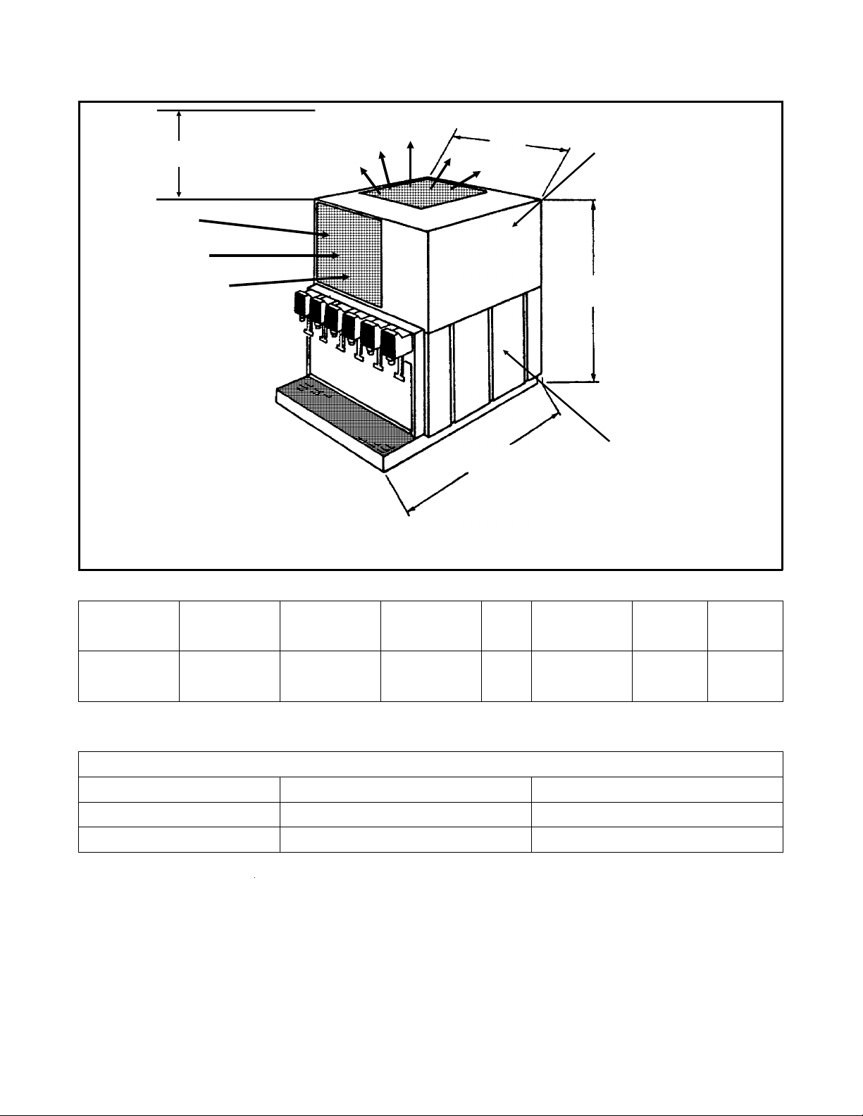
DD40 GENERAL INFORMATION
Page 1
Must Have 13.5"
Clearance Above Unit
COOLING
AIR
IN
AIR OUT
26.5"
18.5"
COVER (SS)
26.5"
ICE/WATER
TANK
SPECIFICATIONS:
MODEL
DD40P+6B-1A
DD40S+6B-1A
DIMENSIONS
H" X W" X D"
26.5 X 18.5 X 26.5
SAME
TANK FINISH
Twin Wall Plastic
Stainless Steel
ELECTRCIAL
115/60/1 - 7 AMPS
SAME
ICE
BANK
40 LB.
SAME
Legs are included. Carbonator (Carb100) and installation kit (KINSDD) not included.
REFRIGERATION CAPACITY: Number of 12-0z. drinks at or below 400 F.
@ 900 F. product, water and ambient@ 750 product, water and ambientDrinks per minute
4
6
150
110
80
45
Scotsman Ice Systems are designed and manufactured with the highest regard for safety
and performance. They meet or exceed the standards of UL and NSF.
Scotsman assumes no liability or responsiblity of any kind for products manufactured by
Scotsman that have been altered in any way, including the use of parts and/or other
components not specifically approved by Scotsman.
Scotsman reserves the right to make design changes and/or improvements at any time.
Specifications and designs are subject to change without notice.
February, 1988
Page 3
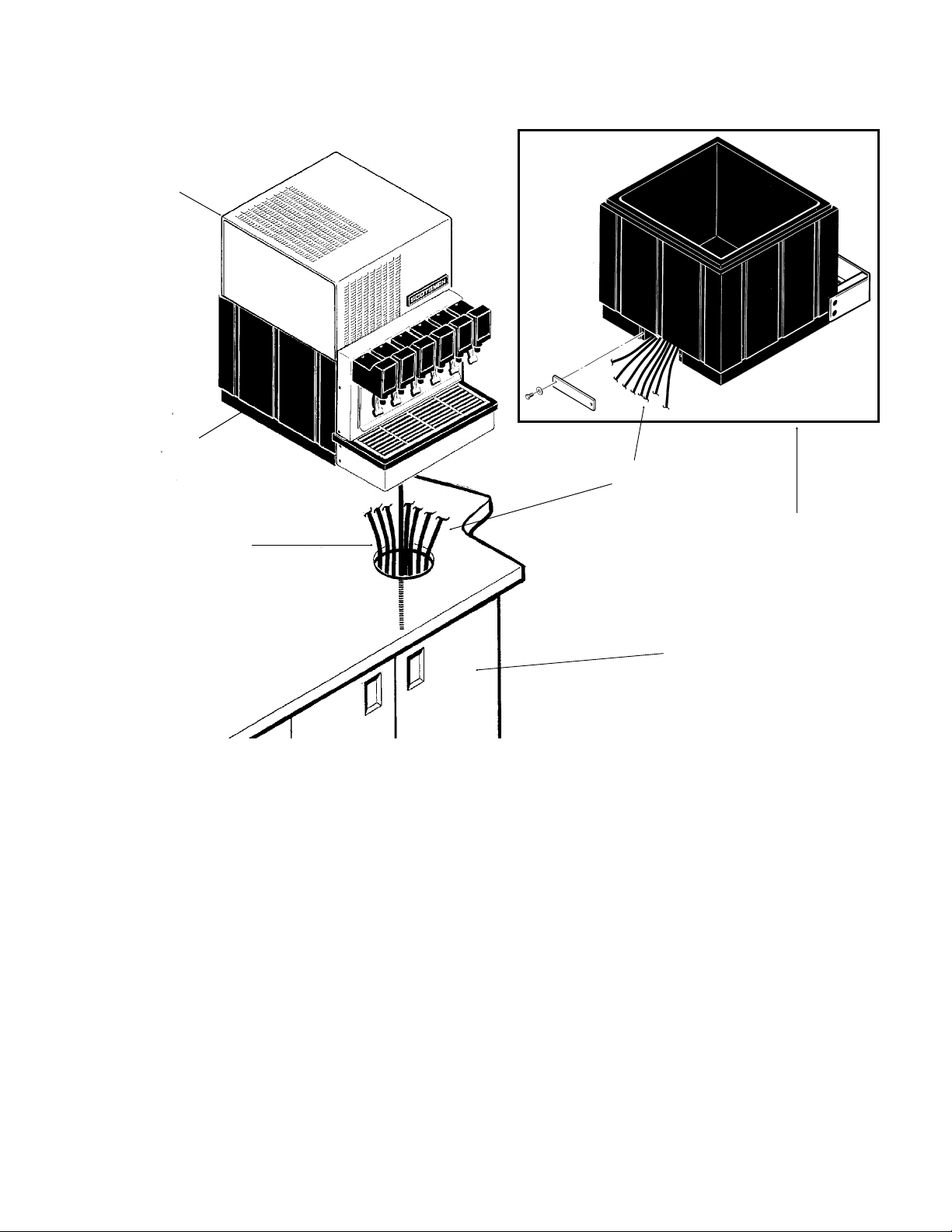
COVER
PRODUCT
HOSES
Page 2
INSTALL LEGS OR
SEAL TO COUNTER
DD40
Installation
POSSILBE
ROUTING OF
PRODUCT HOSES
1. Locate dispenser on the counter. Allow
13.5 inches vertical clearance above unit
for the removal of the cover, and for air
circulation.
In order to comply with National Sanitation
Foundation (NSF) requirements, this unit
must be either elevated above the
countertop sufficiently to provide space for
cleaning under the unit or sealed to the
countertop.
Elevating the unit may be accomplished by
using the included legs. They will screw
into threaded holes in the base of the unit.
Sealing may be accomplished by the use
of room temperature vulcanizing (RTV)
rubber sealant such as General Electric IS
808 Industrial Sealant, Dow Corning 731
(Scotsman part number 19-0529-01) or the
equivalent.
POSSIBLE
ROUTE FOR
PRODUCT HOSES
POSSIBLE LOCATION
FOR CARBONATOR
With the unit located on the counter as
desired:
A. Tilt or lift the unit to expose the bottom
flanges of the base frame.
B. Apply the sealant to cover the bottom
flanges of the base frame.
C. Return the unit to the desired position
on the countertop.
D. Add sealant around the base frame and
countertop to provide a seal with a radius
of 1/2". Follow the sealant manufacturer’s
instructions on the package for working
with the sealant, and cleaning up.
E. Seal around all access holes in the
countertop with Permagum or Mortite caulk
or an equivalent material.
February, 1988
Page 4
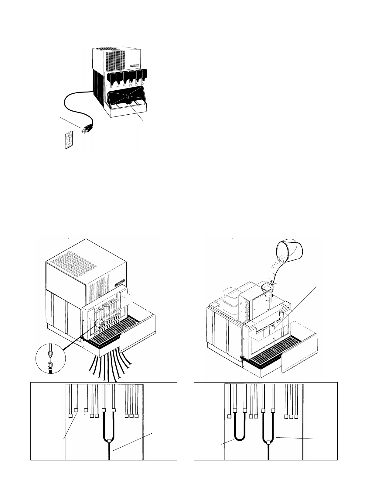
CORD
Page 3
PLUGS INTO
115 VOLT
WALL
OUTLET.
THIS UNIT
MUST BE
GROUNDED
SINK BOTTOM. SINK
DRAIN MUST BE
CONNECTED TO
BUILDING DRAIN
Remove the cover by removing one screw
on the top of the cover.
If installing a remote carbonator, locate it
nearby.
2. Connect the drain line between drain
pan and building drain.
3. Plug electrical supply cord into 115 volt
outlet so ice bank can begin to form. Do
not turn on the carbonator at this time.
DD40
Installation
4. Fill water bath until water flows out of
overflow tube.
5. Connect water supply line (field
supplied) from the remote carbonator to
the dispenser.
Connect both inlet C02 water lines to CO2
water from the carbonator.
Connect water supply line (field supplied)
from building source to carbonator.
Connect syrup lines to dispenser, and
install disconnect sockets.
6. Connect primary CO2 regulator to CO2
tank. Secure secondary regulators to wall
or other stationary surface.
7. Connect CO2 line between outlet of
primary regulator and inlet of secondary
regulators.
8. Connect CO2 lines between outlets of
secondary regulators and syrup tanks.
INSTALL DISCONNECT SOCKETS
WHEN ONE
VALVE IS
NOT
CARBONATED
CONNECT TUBING FILL WITH WATER
OVERFLOW
TUBE
CAP
WITH
GASKET
AND CAP
NUT
CONNECT
TO FRESH
WATER
CO
2
WATER
IN
February, 1988
LOOP
WHEN
NOT
USING
FRESH
WATER
CO
2
WATER IN
Page 5
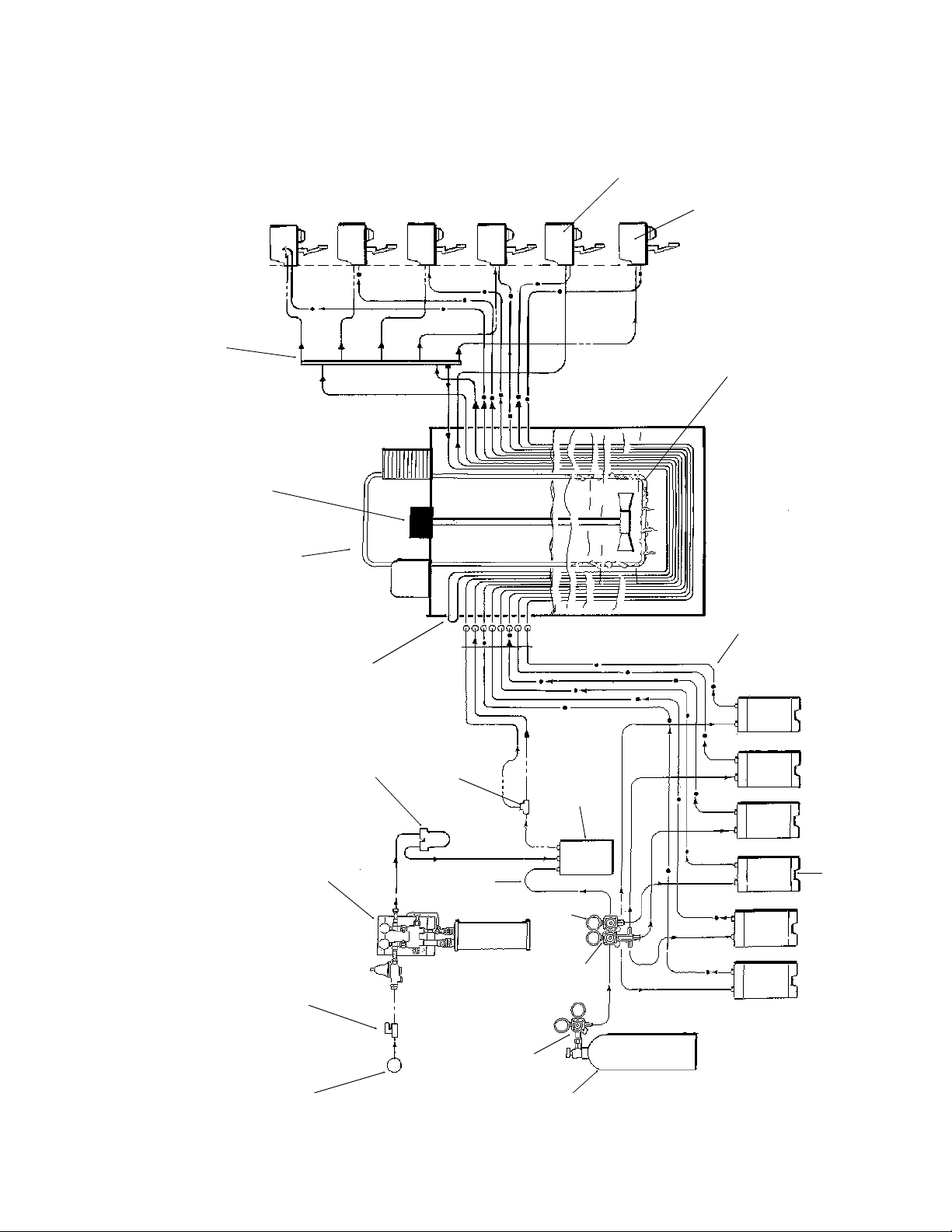
Diet Sysrup Tank
DD40
Page 4
Soda Schematic
Valve
Frese Water
Soda Valve
Carbonated
Water Manifold
Evaporator Coil
Agitator Motor
Refrigeration Unit
Inlet Loop
Fresh Water
Pump
Carbonator
Water Filter
re Water
Carbonato
In
2
CO
Tank
Carbonator
Diet
Reg.
Bank
Syrup Out to Ice
Reg.
Syrup
Hand Valve
2
CO
Regulator
Tank
2
Water Supply
CO
February, 1988
Page 6

BRAIDED
HOSE
KINSDD KIT
DD40
Page 5
Optional Kits
SCOTSMAN FLOAT CARBONATOR
"CARB100" INSTALLATION
1. Remove from carton, inspect for freight
damage. If damaged file a claim with the
freight company immediately.
2. Locate the carbonator on a flat surface.
3. Connect the water supply to the water
"in" (3/8" male flare on pump body) Use
3/8" or larger line.
4. Connect carbonated water line from to
carbonated water "out" (on tank) to the ice
bank CO2 water "in".
5. Install CO2 regulator on CO2 tank.
6. Connect CO2 line from the high
pressure CO2 regulator to CO2 "in" fitting
on the carbonator tank.
7. Install tank disconnects on the end of
the CO2 lines.
8. Turn on CO2 tank, set the high pressure
gauge at 80-100 psi.
Set low pressure gauge at 45 psi. (Diet to
8-15 psi).
9. Check all fittings with soapy water for
possible gas leaks.
10. Turn on water to carbonator.
11. Plug electrical cord into properly
grounded 115 volt outlet.
NOTE: Grounded outlet must be used
for safety. If local codes require hard
wiring, follow these steps.
CARB 100
REMOVE: Cord plug from 115 volt outlet.
Wiring compartment cover from motor.
Wire nut from power supply wire, quick
disconnect terminal from motor terminal,
and ground wire fastener.
Cord from motor.
INSTALL: Appropriate bushing into conduit
hole in motor.
Permanent wiring to motor through bushing
into wiring compartment.
One conductor to switch cord with wire nut
removed in step 3 above.
Other conductor to terminal from power
cord was removed.
Ground wire to motor housing with green
grounding screw.
Wiring compartment cover.
Purge CO2 pressure from carbonator once
or twice while filling by pulling up on
pressure relief valve on the top of the
carbonator tank.
12. Connect syrup lines from syrup tanks
to dispensing lines on ice bank (located
behind the front panel).
13. Connect gas to syrup tanks.
14. Adjust soda valves for proper mix.
15. CO2 tanks should always be secured
to prevent them from falling over.
HIGH PRESSURE
REGULATOR
TWO LOW PRESS.
REGULATORS
February, 1988
FITTINGS
Page 7

DD40
Page 6
Start Up
(Only after ice bank has formed)
1. Turn CO2 on.
2. Set high pressure regulator to 80-100 PSI
3. Set low pressure regulator to 40-50 PSI
4. Set diet pressure regulator (if used) to 8-10 psi.
5. Connect syrup tanks and gas disconnects to syrup tanks.
6. Check for CO2 leaks by turning CO2 tanks off for 4-5 minutes. If the high pressure guage
drops, there is a CO2 leak. Then check each fitting with a soap solution.
7. Turn on the water.
8. Plug in or switch on the carbonator.
9. Purge CO2 gas pressure from the carbonator once or twice while filling by pulling up on
pressure relief valve on the top of the carbonator.
10. Actuate each valve until both water and syrup flow.
11. Check each valve for proper adjustment. Flow rate per valve should be 1.25 oz. per
second of carbonated water, and .25 oz. per second syrup for standard valves. For a fast
flow valve, flow rate should be 2.5 oz. per second of carbonated water, and .5 oz. per
second syrup.
12. Replace cover and screws.
13. Check that the CO2 tanks are secure from falling over.
14. If water noise occurs, add water to bath.
15. Allow machine to build ice bank before dispensing product at maximum draw rate.
February, 1988
Page 8

FOR THE OPERATOR
Page 7
This section covers operating controls,
daily pre-operation check, unit operation,
adjustments, replenishing CO2 and syrup
supplies, and daily cleaning.
Operating Controls.
Dispensing valve levers, located below the
dispensing valves, need only to be pressed
with a cup or glass to dispense product.
Dispensing carbonated water only. On two
of the valves there is a separate lever for
dispensing water only. On the carbonated
valve, actuating this lever will cause the
valve to dispense carbonated water only. If
there is a non-carbonated valve, activating
it will dispense plain water.
VALVES WITH
"WATER ONLY"
LEVERS
Daily Check
1. Make sure that the CO2 cylinder primary
regulator assembly 1800 psi gauge is not
in the shaded ("change CO2 cylinder")
portion of the dial. If so, CO2 cylinder is
almost empty, and must be replaced.
2. Sufficient syrup supply in all syrup tanks.
If not, replenish syrup supply.
3. Make sure drip tray and grill are clean.
4. Make sure soda valve nozzles are clean.
DD40
Replenishing CO2 Supply
Note: When indicator on CO2 cylinder
regulator 1800 psi gauge is in the shaded
area, the cylinder is almost empty and
should be changed.
1. Fully close (clockwise) CO2 cylinder
valve.
2. Slowly loosen CO2 regulator assembly
coupling nut allowing CO2 pressure to
escape, then remove regulator assembly
from CO2 cylinder.
3. Unfasten safety chain and remove
empty CO2 cylinder.
////////////////////////////WARNING/////////////////////////
To avoid personal injury and/or property
damage, always secure CO2 cylinder
with a safety chain to prevent it from
falling over. Should the valve become
accidentally damaged or broken off,
CO2 cylinder can cause serious
personal injury.
/////////////////////////////////////////////////////////////////////
4. Position CO2 cylinder and secure with
safety chain.
5. Make sure gasket is in place inside CO2
regulator coupling nut, then install regulator
on CO2 cylinder.
6. Open (counterclockwise) CO2 cylinder
valve slightly to allow lines to slowly fill with
gas, then open valve fully to back seat
valve. (Back seating valve prevents
leakage around valve shaft.)
7. Check CO2 connections for leaks.
Tighten loose connections.
Replenishing Syrup Supply.
1. Remove CO2 disconnect (grey) and
syrup disconnect (black) from empty syrup
tank, then remove tank.
2. Place full syrup tank in position, then
connect CO2 disconnect (grey) and syrup
disconnect (black) to full syrup tank.
Syrup Flavor Change.
Sanitize applicable syrup system as
instructed, then install full tank of new
flavor syrup.
February, 1988
Page 9

SPRING
CLEAN THE
CONDENSER
DD40
Page 8
FOR THE OPERATOR
Cleaning and sanitizing
1. Remove grill from sink.
2. Wash out sink, and then rinse with warm
water allowing water to run down the drain.
3. Wash the grill, then rinse with clean
water. Place back in sink.
4. Clean all exterior surfaces of the unit
with a sponge. Rinse out the sponge with
clean water, wring excess water out of the
sponge, and wipe off external surfaces of
the unit. Wipe unit with a clean soft cloth.
Do NOT use abrasive type cleaners.
5. Clean valve nozzles. Looking down from
the top of the unit, turn the nozzle
clockwise and down to remove it. Clean
with soap and water, rinse with clean hot
water, and allow to air dry. Replace on the
valve.
Clean the condenser twice per year.
1. Disconnect electrical power.
2. Remove one screw, and the cover.
3. Remove condenser filter, and clean it
with water.
4. Inspect condenser fins, if light cannot be
seen through the fins, the condenser
needs to be cleaned by either vacuum,
compressed air, or coil cleaner. Do Not use
a wire brush.
5. Replace the filter, and the cover.
6. Reconnect the electrical power.
GAS CHECK VALVES
(At the low pressure outlet of the CO
regulator).
The CO
inspected and serviced at least one per
year under normal conditions, and always
after any servicing or disruption of the CO
system.
Always replace the quad ring seal each
time the gas check valves are serviced.
tank
2
system gas check valves must be
2
2
February, 1988
QUAD RING
BALL
RETAINER
BODY
Page 10

Adjustments
Page 9
There is an adjustment for both the water
and the syrup.
Adjustment screws are located under the
valve cover, and behind the solenoid.
1. Facing the valve, the screw on the right
hand side is the syrup adjustment. The
Valve service
To remove:
Push release lever up (located under the
cover on the right side of the valve, near
the back) and pull out the valve. There are
ball checks to automatically shut off the
water and syrup.
Pull apart the electical connectors to the
valve, and remove the valve.
To service:
• Rubber Seats(ring actuators):
Remove the four screws in the back of the
rear section. This will let the front and rear
section seperate and expose the ring
actuators.
The ring actuators are reversable, and
interchangeable. When either reversing, or
replaceing them, place the rings of the
actuators into the groves and align the
DD40
FLOW
CONTROL
ADJUSTER
screw on the left hand side is the water
adjustment.
2. Turn either screw counter clockwise to
increase flow.
stainless steel lever of the actuator with the
center of the notch in the front section.
Replace the rear section, be sure that the
ring actuators seat in the groves of the
front and rear section.
• Flow Controls:
The adjusting screws and springs may be
removed by first removing solenoid and
then the entire top plate. The adjusting
screws and springs are interchangeable.
To remove pistons, remove the entire top
plate, then remove the retaining spring on
the tip of the adjusting screw. The spring
piston should slide off. Pistons are color
coded:
Water is green
Syrup is red
Diet syrup is grey.
PISTON
RING ACTUATOR
February, 1988
Page 11

SANITIZING
Page 10
The dispenser’s syrup systems should be
sanitized periodically as prescribed by the
local health authority or the syrup supplier,
whichever has jurisdiction.
Recommended sanitizing agents are
"Chlor-tergent" (Oakite Products Co.) or
"Diversal CX" (Diversey-Wyandotte
Chemical Co.)
Use an empty, clean syrup product tank in
which to mix the sanitizing solution.
Prepare the sanitizing solution by
dissolving the required amount of
concentrate to supply 200 PPM (parts per
million) available sanitizer in enough water
to flush and sanitize the number of circuits
to be cleaned; five gallons of sanitizer
should be adequate for sanitizing a five
flavor dispenser. Water temperature should
be between 750F. and 1250F.
To sanitize syrup systems:
1. Remove quick disconnect sockets from
syrup product tank. Wash sockets in warm
potable water, connect sockets to tank
containing sanitizing solution.
2. Open dispensing valve to allow
sanitizing solution to push syrup out of
product line, cooling coil, and valve.
DD40
Continue drawing until sanitzing solution
has purged all syrup from system and then
close valve.
3. Allow sanitizing solution to remain in
system for ten (10) minutes.
4. To remove sanitizing solution from
system, remove tank containing solution
and connect a tank containing clean,
uncontaminated syrup. Operate dispensing
valve until all sanitizing solution has been
removed from the system.
/////////////////////////Caution//////////////////////////////
Failure to remove all sanitizer could create
a health hazard.
///////////////////////////////////////////////////////////////////
Repeat sanitizing procedure for each syrup
system (valve) in the dispenser.
/////////////////////////////WARNING////////////////////////
To Avoid Possible Personal Injury Or
Property Damage, Do Not Attempt To
Remove Cover From The Pressurized
Tank Until All Pressure Has Been
Released From The Tank.
/////////////////////////////////////////////////////////////////////
Clean, rinse, and dry utensils. Store them
for future use.
February, 1988
Page 12

DD40
he
re.
e
re
,
Page 11
SERVICE DIAGNOSIS
Symptom
..........Probable Cause
.....................Remedy
Water to syrup ratio too low or too high
..........1. Dispensing valve syrup flow regulator not properly adjusted.
.....................1. Adjust Water to Syrup ratio.
..........2. CO2 gas pressure to syrup tanks insufficient to push syrup out of the tank
.....................2. Adjust syrup tanks secondary CO2 regulator as instructed.
Adjustment of dispensing valve syrup flow regulator does not increase to desired
water to syrup ratio.
..........1. No syrup supply
.....................1. Replenish syrup supply as needed.
..........2. Syrup tank quick disconnects not secure
.....................2. Secure quick disconnects
..........3.Syrup tanks secondary CO2 regulator out of adjustment
.....................3.Adjust syrup tanks secondary CO2 regulator.
..........4.Dispensing valve, syrup tank quick disconnect, or syrup line restricted.
.....................4.Sanitize syrup system as instructed.
Dispensed product carbonation too low.
..........1. Carbonator primary CO2 regulator out of adjustment for existing water conditions or
..........temperature.
.....................1. Adjust carbonator primary CO2 regulator
..........2. Air in carbonator tank
.....................2. Vent air out of carbonator tank through relief valve. Actuate dispensing valve
.....................carbonated water lever to make carbonator pump cycle on.
..........3. Water, oil, or dirt in the CO2 supply.
.....................3. Remove contaminated CO2. Clean CO2 system (lines, regulators, etc.) using a
..................... mild detergent. Install a clean CO2 supply.
Dispensed product produces foam as it leaves dispensing valve.
..........1. No ice in ice bank.
.....................1. Check if overusing, if not, refrigeration system may have a dirty condenser. If t
.....................condenser is clean, and the agitator motor is running, the refrigeration system
.....................may need service.
..........2. Carbonator CO2 regulator pressure too high for existing water conditions or temperatu
.....................2. Reduce carbonator CO2 regulator pressure setting.
..........3. Syrup over carbonated with CO2 as indicated by bubbles in inlet syrup lines leading
.......... to the unit.
.....................3. Remove syrup tanks quick disconnects. Relieve tank CO2 pressure, shake tank
..................... vigorously, then relieve tank CO2 pressure as many times as necessary to remov
..................... over carbonation.
..........4. Dispensing valve restricted or dirty.
.....................4. Sanitize syrup system as instructed.
..........5. Dirty water supply.
.....................5. Check water filter. Replace cartridge. NOTE: If the water supply is dirty, be su
.....................to flush lines & carbonator completely. If needed, remove lines to carbonator tank
.....................invert tank and flush tank and all inlet lines to remove any foreign particles or dirt.
February, 1988
Page 13

g
DD40
Page 12
SERVICE DIAGNOSIS
No product (only water) dispensing from all valves.
..........1. Out of CO2
.....................1. Check CO2 supply.
Must push cup lever further back than normal to dispense product.
..........1. No power to unit.
.....................1. Check that it is plugged in.
..........2. Coil in valve not working.
.....................2. Replace coil.
..........3. Micro switch not working.
.....................3. Replace microswitch.
..........4. Disconnected or broken wiring to dispensing valves.
.....................4. Connect or replace wiring.
..........4. Transformer not working.
.....................4. Replace transformer.
Only carbonated water dispensed.
..........1. Quick disconnects not secure on syrup tanks.
.....................1. Secure quick disconnects on syrup tanks.
..........2. Out of syrup.
.....................2. Replenish syrup supply as instructed.
..........3. Syrup tanks secondary CO2 regulator not properly adjusted.
.....................3. Adjust syrup tanks secondary CO2 regulator.
..........4. Inoperable dispensing valve.
.....................4. Repair dispensing valve.
..........5. Dispensing valve syrup flow regulator not properly adjusted.
.....................5. Adjust dispensing valve.
..........6. Dispensing valve, syrup tank quick disconnects, or syrup lines restricted.
.....................6. Sanitize syrup system.
Only Syrup Dispensed
..........1. Plain water inlet supply line shutoff valve closed.
.....................1. Open plain water inlet supply line shutoff valve.
..........2. Carbonator power cord unplugged from the electrical outlet.
.....................2. Plug carbonator in.
..........3. Carbonator primary CO2 regulator not properly adjusted.
.....................3. Adjust carbonator primary CO2 regulator.
Dispensed product comes out of the dispensing valve clear but foams in the cup or
glass.
..........1. Oil film or soap scum in cup or glass.
.....................1. Use clean cups or glasses.
..........2. Ice used for finished drink is too cold.
.....................2. Do not use ice directly from a freezer. Allow the ice to become "wet" before usin
February, 1988
Page 14

DD40 REMOVAL AND REPLACEMENT
FERRULE CRIMP TOOL
Page 13
/////////////////////WARNING////////////////////////////
Disconnect Electrical Power before
beginning work on the machine.
////////////////////////////////////////////////////////////////////
Ice Thickness Thermostat:
1. Unplug machine from the power source.
2. Remove the cover.
3. Remove the thermostat cover.
4. Pull bulb and capillary line out of bulb
well.
5. Disconnect wires from thermostat.
6. Remove screws holding body to frame,
remove thermostat from ice bank.
7. Reverse to reassemble.
Agitator Motor:
1. Unplug machine from power source.
2. Remove cover.
3. Disconnect wires from motor at junction
plug.
4. Remove two screws, and pull motor up
and out of the ice bank.
5. Reverse to reassemble.
Soda Valve:
1. Switch off Carbonator
2. Turn off Water.
3. Unplug ice bank.
4. Turn off CO2, and at a working valve,
dispense until syrup/water stops.
5. At the valve to be removed:
Remove two screws, pull valve cover up
and off
Move metal lever found in valve up.
Pull valve body out of the mounting block.
Disconnect electrical wires at the junction
plug.
6. After repair or replacement of the valve,
reverse to reassemble.
Refrigeration Chassis:
1. The refrigeration section of the DD40
can be removed from the soda lines,
valves and main body. This is useful when
taking it to the shop for repair or cleaning.
A. Disconnect electrical power.
B. Remove cover.
C. Unplug refrigeration power from the
connection at the right front of the unit.
D. Unplug the low voltage (transformer to
soda valves) connection at the junction
plug at the right front of the machine.
E. Remove 4 screws holding the chassis to
the base.
F. Lift up and remove chassis.
2. After repair or cleaning, reverse to
reassemble.
BRAIDED TUBING INSTALLATION
When installing the braided tubing using
the kit KINSDD, note that the kit contains
two types of clamps; oetiker an ferrule.
If using the oetiker clamps, a pincer
specifically designed for this is
recommended.
KETIKER PINCER
When using the ferrule type, the use of a
special crimp tool is mandatory.
Instructions are porvided with the tool.
Die set No. 47 works well with the ferrule
and tubing provided with the kit.
February, 1988
Page 15

QUICK
DISCONNECTRELEASE
QUICK DISCONNECT SECTION
DD40
Page 14
BOOTH VALVE
ADJUSTING
SCREW
TOP PLATE
TOP PLATE
GASKET
SOLENOID
ASSEMBLY
O-RING
PISTON
CUP
ACTUATOR
SOLENOID
LEAD
MICRO
SWITCH
RETAINING ROD
REAR SECTION BODY
VALVE COVER
RELEASE ACTUATOR
VALVE NIPPLE
CARB. WATER
ACTUATOR
FRONT BODY
SECTION
SPOUT INSERT
RING ACTUATOR
COVER PLATE
BOTTOM
SPOUT
February, 1988
ACTUATOR
SPRING
Page 16

CARB100 REMOVAL AND REPLACEMENT
Page 15
(OPTIONAL EQUIPMENT)
////////////////////////WARNING/////////////////////////////
Disconnect electrical power before
beginning to work on the unit.
//////////////////////////////////////////////////////////////////////
1. Unplug Carbonator.
2. Turn off CO2
3. Turn off water.
4. Bleed CO2 pressure off at soda valve or
relief valve on carbonator tank.
5. Any component in the Carbonator may
now be removed and replaced, including:
PUMP MOTOR
DD40
Float Control, disconnect wires at the
motor, and remove three screws from the
collar at the top of the carbonator tank, pull
float control up and out.
Check Valves, unscrew selected valve from
tank.
Carbonator pump, no internal service parts,
remove and replace.
Carbonator motor, no internal service parts,
remove and replace.
6. Reverse steps of removal to reassemble.
FLOAT PROBE
PUMP
WATER
CHECK
VALVE
February, 1988
 Loading...