

Page 1

Instructions
Installation and Operation of the TPDL1 Prodigy Smart-Board™
Datalogger
Scotsman's Advanced Feature Smart-Board is an optional add on electronic device that can be
applied to most Prodigy models. It can be used:
With the standard controller
•
With the standard controller and the SmartLock Out Control (KSL)
•
With the standard controller and the Vari-Smart™ Ice Level Control (KVS)
•
With the standard controller, and both the KSL and the KVS
•
Smart-Board abilities include:
USB connection to Scotsman's Prodigy TechTool software
•
Data Logging
•
Data Display
•
Kit Contents
Pre-mounted Smart-Board, connecting cable, USB cable, CD-ROM.
•
Installation: Temporary Data Logger
1. Depress and hold the Off button until the machine shuts Off (Status light will go out).
2. Disconnect electrical power from the ice machine.
Note: Connecting the TPDL1 to a controller that is powered is NOT recommended, as it
might result in a reset of the controller.
3. Remove front panel.
4. Remove screw holding control cover to control box, swing control & cover open.
5. Route wire into back of control box. Locate datalogger in a secure spot in the cabinet.
6. Connect supplied wire from Smart-Board box to main controller Accessory connection.
7. Close the control box cover.
8. Reconnect electrical power. Display will show time and date (US Central Time). See time set
section for instructions on changing the time. The prior data should be cleared so the datalogger
only contains information on the machine it is now connected to. See page 3 for instructions on
clearing the data.
17-3139-01.
1
Page 2
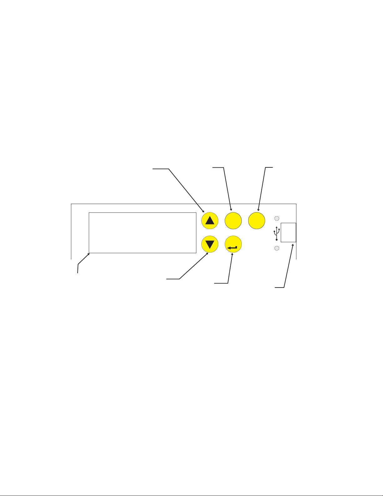
Use of Smart-Board Buttons:
SmartBoard Advanced Feature Control™
See Instructions for Available Features
34
SEL
02-4293-01 Rev A.
ENTER
ESC
Scroll Up: Changes the display to a menu item higher on the menu list or goes up one
number on a setting
Scroll Down: Changes the display to a menu item lower on the menu list or goes down
one number on a setting
Select Button: Use to make changes to settings.
Enter Button: Changes display to a sub menu list.
Escape Button: Changes display to the main menu.
Scroll Up
Button
Display Area
The Smart-Board can display Warnings and Data.
Data Available:
Scroll Down
Button
Select
Button
Enter
Button
Escape Button
USB
Connection
•
Time, Date
•
Average freeze time
•
Minimum freeze time
•
Maximum freeze time
•
Average harvest time
•
Minimum harvest time
•
Maximum harvest time
•
Diagnostic code with timestamp
•
Compressor run time
•
Freeze cycles
•
Flush level used
•
Water quality
•
Operational mode
•
Water temperature
•
Discharge temperature
•
Voltage from the transformer
•
Bin stat input status
Page 3

Warnings - will appear in display after malfunction
Self Test Fail
•
Long Freeze Pend
•
Long Freeze Err
•
Long Harvest Err
•
Check Water
•
Communication Features:
The datalogger can communicate information in two ways:
Display: The two line display is controlled by the buttons on the front of the datalogger.
•
USB: There is a USB connection on the front of the SmartBoard. It can be used by a laptop
•
or other PC type computer to read, download or log data. Scotsman software is required.
Other Features:
Although use with the datalogger version of the Smart-Board is unlikely, 7 Day Programmable Ice
Level Control is available when the optional Vari-Smart adjustable ice level control is installed on
the Prodigy controller. Instructions for programing are included in these instructions. Some
features are not available when installed on a cuber that has Rev 1 software. Rev 2 use
began approximately March 2007.
Suggestions for use:
High Temp Error
•
Sump Temp Sensor
•
Disch Temp Sensor
•
Min Freeze Pend
•
Min Freeze Error
•
Check Water Warn
•
Long Freeze Warn
•
Long Harv Warn
•
High Temp Warn
•
The datalogger will be most useful when connected to a machine that needs further diagnostics. It
can record information that otherwise would be difficult to get. Of particular use will be freeze cycle
time, harvest cycle time, power interruptions and any diagnostic shut downs. The Status
Performance
sections contain that type of information.
and
Page 4

Menu Tree
Date - preset
Time - preset to Central Time
Warnings
No warnings
See prior page for warning list
Base Faults
Fault code 1:
Fault code 2:
Fault code 3:
Fault code 4 :
Fault code 5 :
Fault code 6 :
Fault code 7 :
Fault code 8 :
Fault code 9 :
Fault code 10 :
Adv (advanced) Faults, descriptions of
faults with time and date of occurrence
Self test failure
Long Freeze Pend
Long Freeze Strikeout
Long Harv Pend
Long Harvest Strikeout
Check Water
High Temp Error
Disch Temp Error
Sump Temp Sensor
Discharge Temp Sensor
Min Freeze Pend
Minimum Freeze Strikeout
Status
Discharge Temp
Sump Temp
Board Voltage
Bin Level
Bin Setpoint
Freeze Timer
Harvest Timer
Freeze Counter
Water Quality
Flush Used
Long Frz Strike
Long Hrv Strike
Min Frz Strike
Pwr Interrupts
Bin Stat
Disch Frz Set
Cleaning
Clean interval
Next Clean Due
Last Clean
Flush level
Set Flush Level
Performance
Percent run time:
Min Freeze Time
Max Freeze Time
Avg Freeze Time
Min Harvest Time
Max Harvest Time
Avg Harvest Time
Clear History
Test
Water Test
Water fill time
Esc to cancel test
Timers
Compressor run time
Comp resettable
Press enter to reset
Pwr up time
Pwr resettable
Press enter to reset
Revision
AFB SW Revision
Controller SW
US Bin Level SW
AFB Hardware Rev
Controller HW
Setup
Date
Set date
Time
Set time
Model Number
Set model number
Serial Number
Set serial number
Manufacturer
Equipment Name
Manufacture date
Set Manufacture Date
Install Date
Set Install Date
Contact Name
Set Contact Name
Contact Phone Number
Set contact phone
Audible alert
Set audible alert on / off
Clear current log file
Press Select to clear log
Clear fault history
Press Select to clear fault code
Logging rate
Set logging rate
Fill time warning xxx seconds
Set fill time warning
Freeze time warning xx minutes and seconds
Set freeze time warning
Harvest time warning minutes and seconds
Set harvest time warning
Discharge temp warning in degrees F
Set discharge temp warning
PGM Bin Level*
Bin Level Ctrl
Set Bin Level Ctrl On Off
Monday time 1
Monday level 1
Monday time 2
Monday level 2
Monday time 3
Monday level 3
Monday time 4
Monday level 4
Tuesday time 1
Tuesday level 1
Tuesday time 2
Tuesday level 2
Tuesday time 3
Tuesday level 3
Tuesday time 4
Tuesday level 4
Wednesday time 1
Wednesday level 1
Wednesday time 2
Wednesday level 2
Wednesday time 3
Wednesday level 3
Wednesday time 4
Wednesday level 4
Thursday time 1
Thursday level 1
Thursday time 2
Thursday level 2
Thursday time 3
Thursday level 3
Thursday time 4
Thursday level 4
Friday time 1
Friday level 1
Friday time 2
Friday level 2
Friday time 3
Friday level 3
Friday time 4
Friday level 4
Saturday time 1
Saturday level 1
Saturday time 2
Saturday level 2
Saturday time 3
Saturday level 3
Saturday time 4
Saturday level 4
Sunday time 1
Sunday level 1
Sunday time 2
Sunday level 2
Sunday time 3
Sunday level 3
Sunday time 4
Sunday level 4
Network Configuration*
IP Address
Subnet mask
Default gateway
DHCP Enable
Update IP Address
Update Subnet mask
Update default Gateway
Update DNS
Update DHCP
* Included but does not apply
to this version Smart-Board.
4
Page 5

Advanced Fault Definitions
Self test failure
The controller checks for proper operation at power up. If the check shows a problem, this warning
or fault will be displayed.
Long Freeze Pend
If the ice machine fails to make ice within the maximum time limit, the controller will note that and
display this warning or fault while it is attempting another freeze cycle.
Long Freeze Strikeout
If the ice machine fails to make ice within the maximum time limit for a third consecutive time, this
warning or fault will be displayed and the machine will be shut down.
Long Harv Pend
If the ice machine fails to release ice within the maximum time limit, the controller will note that and
display this warning or fault while it is attempting another freeze cycle
Long Harvest Strikeout
If the ice machine fails to release ice within the maximum time limit for a third consecutive time,
this warning or fault will be displayed and the machine will be shut down.
Check Water
If the water level sensor does not sense a full reservoir during the maximum time limit, this warning
or fault will be displayed. The machine will automatically attempt to fill with water.
High Temp Error
If the discharge temperature exceeds 250 degrees at any time, the controller will shut the machine
down and display this warning or fault.
Sump Temp Sensor
The water temperature sensor's resistance varies with the water temperature. If the resistance is
beyond what the sensor's capability is, this warning or fault is displayed.
Discharge Temp Sensor
The discharge temperature sensor's resistance varies with the refrigerant temperature. If the
resistance is beyond what the sensor's capability is, this warning or fault is displayed.
Min Freeze Pend
If the controller senses finished ice thickness before the minimum freeze time has elapsed, this
warning or fault will be displayed.
Minimum Freeze Strikeout
If the controller senses finished ice thickness before the minimum freeze time has elapsed three
cycles in a row, this warning or fault will be displayed if the machine and the machine will be shut
down.
Page 6
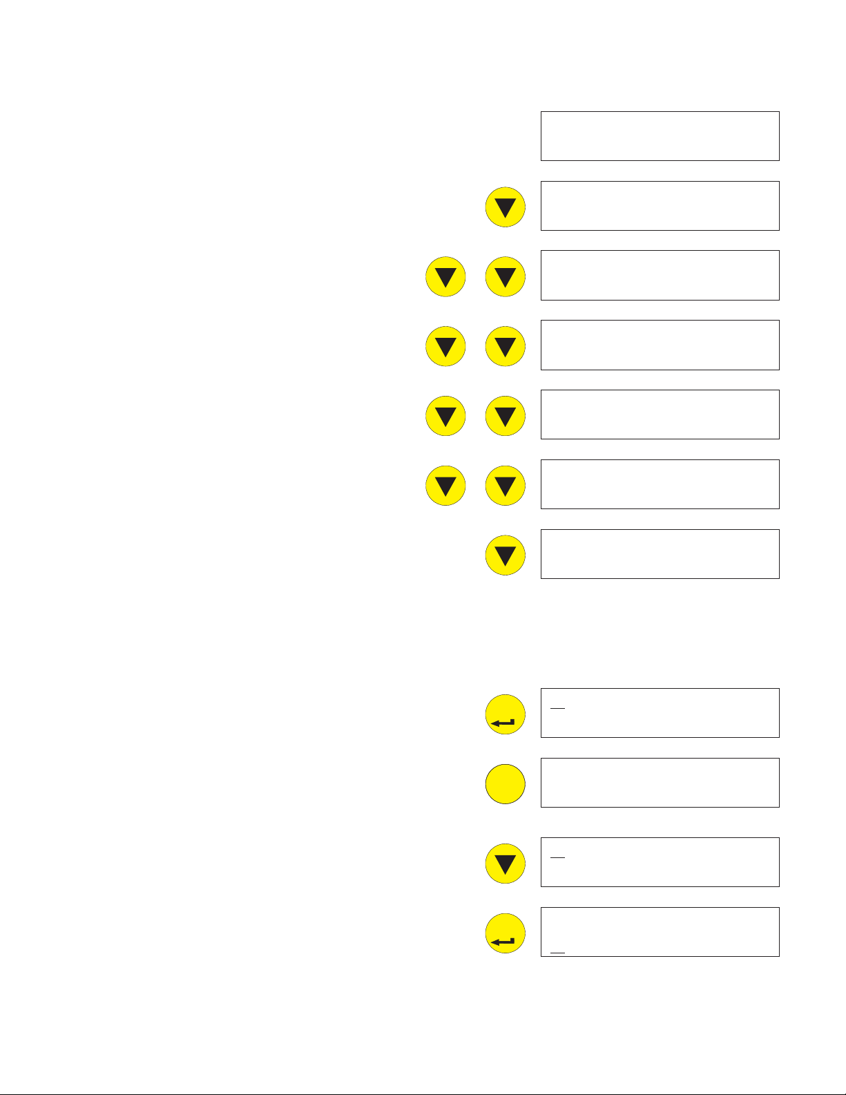
Smart-Board Button Use:
ENTER
ESC
ENTER
Menu Groups: Push and release the down arrow key to scroll
down to the next group.
Date - preset
Time - preset to Central Time
Warnings
Base Faults
Adv (advanced) Faults
Status
Cleaning
Performance
Test
Timers
Revision
Setup
Date: 12-20-2006
Time: 03:33:10PM
Warnings
Base Faults
Adv Faults
Status
Cleaning
Performance
Test
Timers
Revision
Setup
PGM Bin Level
Within each group are several screens of information or
settings, like times, that can be changed.
Date and Time Groups: No submenus are available.
Warnings: Press and release the Enter button to see
information on current Warnings.
Press and release ESC to return to the prior menu.
Base Faults: Press and release the Down arrow to
underline the B in Base Faults, then the Enter button
to see in the display:
Most recent failure (labeled 0) and how long ago it
occurred (in hours), then press and release the
down arrow to see:
Second to most recent failure (labeled 1) and how
long ago it occurred (in hours), then press and
release the down arrow to see:
Setup
PGM Bin Level
W arnings
Base Faults
No Warnings
W arnings
Base Faults
Warnings
Third, fourth, fifth, and so on up to ninth where the
list ends.
6
B
ase Faults
Page 7

If there are no errors, the screen will display End of
ESC
ENTER
ESC
Errors.
Press and release the escape button to return to the
main menu tree.
End of Errors
Press and release the down arrow key to underline
the A in Advanced Faults.
Advanced Faults: Press and release the Enter button
to see in the display:
Most recent failure and the exact time it occurred.
Pressing and releasing the down arrow cycles
through the other failures back to the oldest.
Several examples are listed to the right.
Base Faults
A
dv Faults
Long Harv Pend
04-15-07;08:15AM
Long Freeze Pend
04-01-07;07:11AM
Check Water
03-12-07;11:12AM
High Temp Error
03-12-07;05:00AM
At the end of the list the display will show directions
to go back to the main menu.
Press and release the escape button to return to the
main menu tree.
Min Freeze Pend
02-28-07;04:20PM
Sump Temp Sensor
01-15-07;12:01AM
up arrow = back
esc = main menu
7
Page 8

Press and release the down arrow to underline the S
ENTER
in Status.
Status: Press and release the Enter button to see:
Adv Faults
S
tatus
Discharge Temp
release the Down arrow key to see:
Sump Temp
the Down arrow key to see:
Board Voltage
and release the Down arrow key to see:
Bin Level
Displays level currently sensed. Will display 255
when no Vari-Smart present. Then press and
release the Down arrow key to see:
Bin set point
press and release the Down arrow key to see:
Freeze Timer
release the Down arrow key to see:
Harvest Timer
release the Down arrow key to see:
number. Use with Vari-Smart control.
in degrees F., Then press and
in degrees F. Then press and release
- from the transformer. Then press
: Used with Ultrasonic control. Then
: Freeze time. Then press and
: Harvest time. Then press and
Discharge Temp:
157
Sump Temp:
38
Board Voltage:
14
Bin Level:
13
Bin Setpoint:
9
Freeze Timer:
00:00
Freeze Counter
arrow key to see:
Water Quality
the reservoir water. Typically between 20 and 60,
lower numbers mean higher mineral content. Then
press and release the Down arrow key to see:
Flush Used: The WaterSense system has selected
this purge setting. Will read 255 if no water in
sump. Then press and release the Down arrow key
to see:
Long Freeze Strike
Number of long freeze errors in memory. Then
press and release the Down arrow key to see:
Long Harvest Strike
Number of long harvest errors in memory. Then
press and release the Down arrow key to see:
Min Frz Strike
Then press and release the Down arrow key to
see:
: Then press and release the Down
.: Measurement of the conductivity of
: Long Freeze Strike number.
: Long Harvest Strike number:
: Minimum freeze strike number
Harvest Timer:
00:00
Freeze Counter:
0
Water Quality:
0
Flush Used:
0
Long Frz Strike:
0
Long Hrv Strike:
0
Min Frz Strike:
0
8
Page 9

Pwr Interrupts: Number and time of power
ESC
ENTER
ESC
ENTER
SEL
interruptions. Then press and release the Down
arrow key to see:
Pwr Interrupts:
0
Bin Stat
bin thermostat is attached or there is no ice on a
thermostat. Then press and release the Down arrow
key to see:
Disch Frz Set
temperature recorded as a set up number. The set
up number is used for determining how long the fan
is off at the end of the freeze cycle.
When done with Status, press and release the ESC
button.
Push and release the Down arrow to put the line
under the C in Cleaning. Then push and release the
Enter button to see.
Cleaning. Press and release the Enter button to see:
The Clean Interval
Down arrow to see:
The Next Clean Due in x HRS
release the Down arrow to see:
: Open or Closed. Open is normal when no
: In degrees F. Shows the discharge
. Then press and release the
. Then press and
Bin Stat:
Open
Disch Frz Set:
0
Status:
C
leaning
Clean Interval:
HR
Next Clean Due
in HRS
Last Clean: x HR Ago
Then press and release the Down arrow to see:
Flush Level
Push and release the SEL arrow key to enter flush
level set mode.
Push and release the Up or Down arrow keys to
change flush level.
Push and release the Enter key to set the new flush
level.
Then press and release the ESC button.
Push and release the Down arrow to put the line
under the P in Performance.
: Set to Auto or 1, 2, 3, 4 or 5.
.
Last Clean:
HR Ago
Flush Level:
1
Set Flush Level:
3
Cleaning
P
erformance
9
Page 10

Then push and release the Enter button to see:
ENTER
ESC
SEL
SEL
ENTER
ESC
Performance
Percent run time
Down arrow to see:
Min Freeze Time
Down arrow to see:
Max Freeze Time.
Down arrow to see:
AVG Freeze Time
Down arrow to see:
Min Harvest Time
Down arrow to see:
Max Harvest Time
Down arrow to see:
. Then press and release the
. Then press and release the
. Then press and release the
Then press and release the
. Then press and release the
. Then press and release the
Percent run
time
Min Freeze Time
00:00
Max Freeze Time
00:00
AVG Freeze Time
00:00
Min Harvest Time
00:00
Max Harvest Time
00:00
AVG Harvest Time
Press and release the Down arrow open last time
to enter the Clear History
release the SEL button to clear the performance
history.
When done with Performance, press and release the
ESC button.
Push and release the Down arrow to put the line
under the T in Test. Then press and release the
Enter button to see:
Test. Press and release the SEL button to begin a
water test. The time to fill the reservoir will be
displayed.
When done with Test, or to cancel it, press and
release the ESC button.
.
screen. Press and
AVG Harvest Time
00:00
Clear History
Performance
T
est
Press select
to start water
10
Page 11

Push and release the Down arrow to put the line
SEL
ENTER
ENTER
SEL
ESC
ENTER
ENTER
under the T in Timers. Then press and release the
Enter button to see:
Timers. Push and release the Enter button to see
Compressor run time
Down arrow to see:
. Then press and release the
Test
T imers
Compressor Run:
HR
Comp Resettable:
Compressor run resettable.
Down arrow to go to the next line or Press
SEL to enter reset mode.
Press Enter to reset compressor run time to 0
Press the Down arrow to go to Power up time
press and release the Down arrow to see:
Power on resettable
to go to the next line or Press SEL to enter
reset mode.
Press Enter to reset Power on time to 0
When done with Timers, press and release the ESC
button.
Push and release the Down arrow to put the line
under the R in Revision. Then push and release the
Enter button to see:
. Press the Down arrow
Press the
. Then
0HR
Press enter to
clear counter
Pwr Up Time:
HR
Pwr Resettable:
HR
Timers
R
evision
Revision. AFB SW Rev
Then press and release the Down arrow to see:
Controller SW
and release the Down arrow to see:
US Bin Level (Vari-Smart) software
press and release the Down arrow to see:
(software rev number) Then press
number.
revision. Then
11
AFB SW Rev
Controller SW
US Bin Level SW
140
Page 12

AFB Hardware Rev (Smart-Board revision)
ESC
ENTER
34
SEL
SEL
ENTER
34
SEL
SEL
ENTER
AFB Hardware Rev
Then press and release the Down arrow to see:
Controller HW
When done with Revisions, press and release the
ESC button.
Push and release the Down arrow to put the line
under the S in Setup.
Then push and release the Enter button to see:
Setup:
View the Date or change it.
To Set Day, Month and Year
Press SEL key to get to Setup screen
Push and release the SEL key to move to another
underlined number.
Push and release the Up or Down arrow key to
change the marked character.
(hardware rev number).
1
Controller HW
1
Revision
S
etup
Date:
Select to change
Set Date:
Date: 12-21-2006
Push and release the Select key to move to the next
character, repeat prior step to change the character.
When done, push and release the Enter key.
Then press and release the Down arrow to view the
time or change it.:
To Set Time
Press SEL key to get to Setup screen
Push and release the SEL key to move the underline
to another number.
Push and release the Up or Down arrow key to
change the marked character.
Push and release the Select key to move to the next
character, repeat prior step to change the character.
When done, push and release the Enter key.
Time:
Select to change
Set Time:
Date: 02:07:51PM
12
Page 13

Then press and release the Down arrow to view the
Model number
Then press and release the Down arrow to view the
Serial number
Then press and release the Down arrow to view the
Manufacturer
Then press and release the Down arrow to view the
Equipment Name
Then press and release the Down arrow to view the
Manufacture date
Then press and release the Down arrow to view the
Install date
.
Model Number
Serial Number
Manufacturer
Scotsman Ice
Equipment Name
Ice Machine
Manufacture Date
Install Date
Then press and release the Down arrow to view the
Contact name
Then press and release the Down arrow to view the
Contact phone number
Down arrow to view the
Audible Alert
Then press and release the Down arrow to view
the. Then press and release the Down arrow to
view the screen to clear the current log file.
Then press and release the Down arrow to view the
Clear Fault History
Down arrow to view the
Logging rate
arrow to view the
.
. Then press and release the Down
. Then press and release the
file. Then press and release the
Contact Name
Contact Phone Nu
Audible Alert
Off
Clear current
log file
Clear Fault
History
Logging rate
13
Page 14

Fill time warning. Then press and release the Down
34
SEL
SEL
ENTER
SEL
ENTER
SEL
SEL
34
ENTER
SEL
arrow to view the
Fill time warning
setpoint
Freeze time warning
Down arrow to view the
Harvest time warning
Down arrow to view the
Discharge temp warning
Any of the above can be modified by changing the settings as
noted below. The warning set points can be adjusted to
match local conditions, so that when they change the
Smart-Board provides a notice of the change.
To Change Setup Settings:
Press SEL key to get to Setup screen. Push and
release the SEL key to move the underline to
another number.
Push and release the Up or Down arrow key to
change the marked character.
Push and release the Select key to move to the next
character, repeat prior step to change the character.
. Then press and release the
. Then press and release the
.
Freeze time
warning setpoint
Harvest time
warning setpoint
Discharge temp
warning setpoint
When done, push and release the Enter key.
Example 1: Set Install Date
Push the Down arrow key until Setup is visible and
the S is underlined. Press Enter.
Repeatedly push and release the Down key until the
Install Date screen appears. Press SEL key to get
to Setup screen
Push and release the SEL key to move the
underline to another number. Push and release the
Up or Down arrow key to change the marked
character.
Push and release the Select key to move to the
next character, repeat prior step to change the
character.
When done, push and release the Enter key.
Revision
S
etup
Set install date
00-00-0000
14
Page 15

Prodigy Software
Installation and Use
Description:
The Scotsman Prodigy Tech Tool is a software program designed to access the datalogger tool.
Requirements:
Windows XP or Vista
•
40 MB disk space minimum. More will be needed if data logging is used.
•
Desktop or Laptop PC with a USB port.
•
Live ice machine with datalogger connected (to install USB driver)
•
Software Installation:
Pre-installation: The datalogger must be UNPLUGGED from the the PC.
1. Insert the CD into the computer’s CD-ROM drive.
2. Follow the program installation instructions. At the finish, do NOT start the application.
• The installation will place 2 icons on the desktop, Prodigy Charting and Scotsman Prodigy.
•
The installation will also set up a Scotsman Prodigy section under Programs (Start > All
Programs > Scotsman Prodigy).
3. After the installation is complete, remove the CD-ROM from the drive.
4. Power up the datalogger and plug the USB connector into the PC and the datalogger.
5. The PC will automatically find the Smart-Board and begin the process to install the driver.
6. Select all default settings for installing the device driver.
7. Installation is now complete.
15
Page 16

Use:
With the datalogger powered and connected to the computer's
USB port, Open Scotsman Prodigy:
Start, All Programs, Scotsman Prodigy, Prodigy
Click on Get. The software will automatically begin
to download the information from the Smart-Board.
Once that is complete either click on Chart or select
a new log file to review.
When you click on Chart, the Column Selection
dialog box will appear. You can select any chart you
want to review. The default is all of them. Click on
OK to go to the next step.
The software will display the Charting information
box. You may have to expand it to see the Chart
Type selection area on the right.
Use the Chart
list of available charts.
Which one of these to use depends
upon what the machine situation is.
For example, if the machine is down,
displaying code 2, indicating a
maximum length harvest cycle, it
would be good to know the freeze
cycle time before the long harvest
cycle. If the freeze cycle time is long,
it may be that no ice is being made,
so none is available to open the
curtain during harvest, causing a
maximum harvest time code. Checking the Base
Faults or Advanced Faults is another way to
understand what occurred and when.
Another example is a complaint of low capacity. The
chart on Power up time
is on all the time. Then a look at the freeze timer
chart will show how often it is cycling. The two will
provide a good idea of the machine's ability to
produce ice.
Type box to display the
should show if the machine
At any time clicking on the Render PDF button will
generate all the charts in PDF format so they can be
saved. Once saved they can be printed or emailed.
Page 17

Chart Definitions:
Freeze timer = Freeze time in seconds.
•
Harvest timer = Harvest time in seconds.
•
Freeze Counter = Continuous freeze cycles (starts over after bin full, power interruption, or
•
ice melt state)
Flush level set point = Flush level setting 0-5.
•
Flush used = 1-5. Flush level used in autoflush (0) mode.
•
Water quality = An indication of water quality where 0-24 Extremely Mineral Laden; 25-30
•
Somewhat Mineral Laden; 31-65 Normal; 66-120 Very Clean; >120 Extremely Clean
Error code - Diagnostic Error Code. Codes listed in software and on next page
•
Op mode = the current mode of the controller. Modes listed in software and on next page
•
Sump temperature = Reservoir water temperature in degrees F
•
Discharge temperature = Discharge temperature in degrees F
•
Supply voltage = approximation of AC voltage to the control board from the transformer.
•
Bin stat = Bin thermostat, when used. 0 open, 1 closed
•
RLO = SmartLock option. 0 not locked, 1 locked
•
Ready to Harvest = Ice thickness sensor. 0 no ice, 1 ice
•
Sump Full = Water level sensor. 0 no water, 1 water
•
Sump Empty = Water level sensor. 0 no water, 1 water
•
Remote = 0 not remote, 1 remote
•
Curtain SW1 = 0 closed, 1 open
•
Curtain SW2 = 0 closed, 1 open
•
• Water Solenoid=0off,1on
•
Water Pump=0off,1on
•
Hot Gas = 0 off, 1 on
•
Condenser Fan/Aux=0off,1on
•
Compressor=0off,1on
•
Purge Valve=0off,1on
•
Power up time= Time power connected to machine.
•
Compressor run = Time compressor has been operating
•
Power interrupts = Number of electrical power interruptions to the machine
•
Bin setpoint = Set point of the Vari-Smart control
•
Bin level (inches) = Ice level measured by the Vari-Smart control
•
HGV counter = Number of times the hot gas valve has cycled. Equals harvest cycles.
•
Auto flush level min = minimum flush used when set to automatic
Page 18

Reference
Error Code Display
Example of generated PDF file
Op Mode Display
 Loading...