

Page 1

AFE400 SERVICE PARTS
This is the parts list for the AFE400. When looking
up part numbers, always check the complete
model and serial numbers to be certain of ordering
the correct parts.
The Air Cooled model has also been manufactured
in 50 Hz.
The water cooled A and B series models have
different water cooled condensers. Be sure to
check the complete model number.
The C series has a different compressor. Be sure
to check the complete model number.
The gear reducer changed design in February
2007. Confirm the part number from the tag on the
gear reducer to supply the correct part.
Plastic tubing is sold by the foot, order 1 unit, and
1 foot will be shipped. Order enough to cover the
length required. Lengths of tubing are listed under
the description column.
Table of Contents
CABINET ............................................. Page 2
AIR COOLED REFRIGERATION ................................. Page 3
WATER COOLED REFRIGERATION .............................. Page 4
RESERVOIR AND TUBING ................................... Page 5
Evaporator ............................................ Page 6
Prior Gear Reducer A31977 ................................... Page 7
Gear Reducer 02-4399-21 or 02-4399-24 or 02-4398-21 .................... Page 8
CONTROL BOX ......................................... Page 9
SCHEMATIC DIAGRAM ..................................... Page 10
WIRING DIAGRAM ........................................ Page 11
January 2009
Page 1
Page 2
10
AFE400 SERVICE PARTS
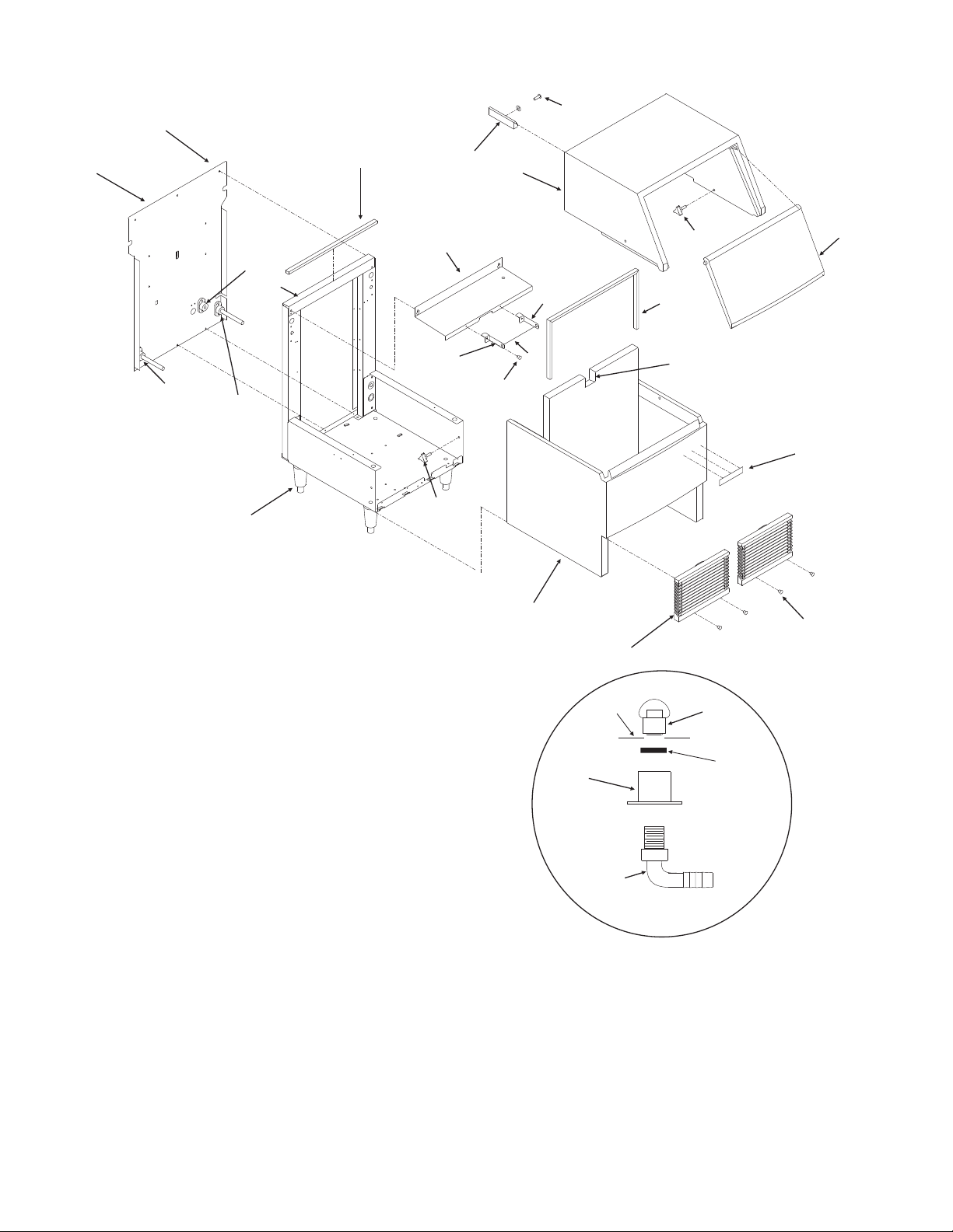
CABINET
20
11
9
21
14
24
8a
ITEM PART
8
7
NUMBER NUMBER DESCRIPTION
1 A35089-020 Hood, includes #3,19,20
2 A35090-002 Door
3 03-1675-01 Knob
4 03-1638-03 Screw
5 02-3153-01 Grill
6 A35088-020 Bin, includes #15,16,16a, 17
7 KLP2E Leg kit
8 02-3692-21 Drain casting - bin
8a 02-3692-22 Drain casting - reservoir
9 A35248-001 Back panel
10 03-1404-29 Sheet metal screw
11 13-0609-01 Gasket, 21.75" req.
12 A35394-001 Bin control bracket
13-0727-00 Grommet
13 03-1638-03 Screw
14 16-1154-22 Water cooled drain fitting
15 02-2809-02 Drain cap
16 02-3108-01 Drain fitting
16a 02-4193-01 Washer - flat
17 16-0822-01 Adaptor
18 15-0808-01 Emblem
19 19-0629-01 Door stop
3
12
19
1
3
12
23
13
6
5
Bin
16
17
22
25
DRAIN
FITTINGS
DETAIL
Not Illustrated:
15
16a
18
4
Scoop, part
number
02-3253-01
20 03-1419-09 Screw
21 A35199-001 Evaporator bracket
13-0727-00 Grommet for cap tube
22 13-0909-01 Bin gasket 36" req.
23 A35395-001 SS Bin control tube (prior)
13-0895-01 Plastic tube - 9” req.
24 A35452-001 Top bracket
25 13-0892-01 Spout grommet
2
September 2010
Page 2
Page 3
AFE400 SERVICE PARTS
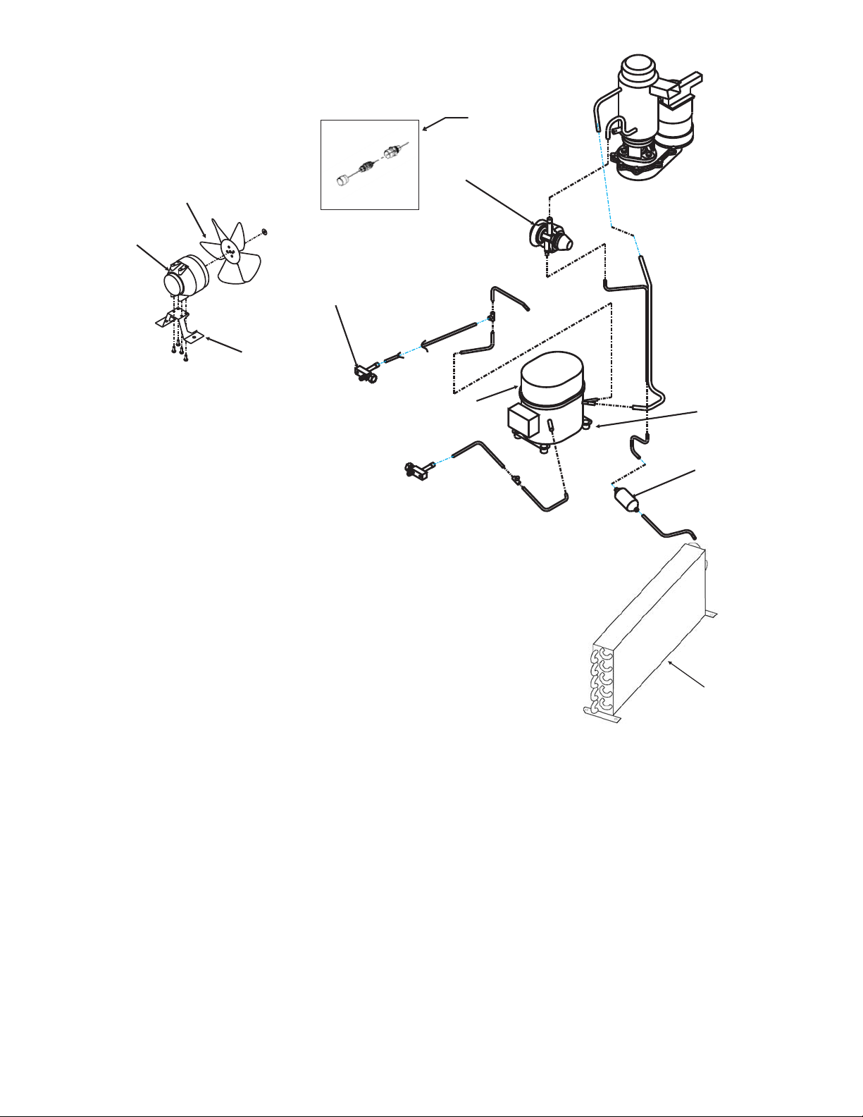
AIR COOLED REFRIGERATION
3
4
2
5
ITEM PART
NUMBER NUMBER DESCRIPTION
1 16-1091-21 1/8 ton TXV
(interchangeable with prior 16-0996-22 - 1/4 ton)
02-3792-02 Insulation
2 16-0832-21 Access Valve
16-0832-02 Stem cap
16-0832-03 Core cap
3 18-8708-01 Fan blade
4 12-1681-23 Fan motor, 115/60/1
18-8709-03 Fan motor, 50 Hz
5 A35246-001 Fan motor bracket
6 03-1677-01 Screw
03-1407-07 Washer
18-2200-27 Sleeve
18-2200-28 Grommet
7 02-3319-01 Dryer
8 18-8844-01 Air cooled condenser
02-3193-01 Air filter (not shown)
9 18-8918-21 60 Hz Compressor*
18-8746-26 50 Hz Compressor*
A or B and 50 Hz C series (Tecumseh
compressor) parts:
18-8746-29 Start capacitor
18-8746-28 Relay
18-8746-27 Overload
18-8746-25 50 Hz Start capacitor
18-8746-24 50 Hz Relay
18-8746-23 50 Hz Overload
11
1
9
10 11-0501-24 Hi pressure cut out
(for those units mfg. with one, use began 12/05)
60 Hz C series (Danfoss compressor) parts:
18-1903-60 60 Hz relay w/overload
18-1901-60 60 Hz start capacitor
* Includes relay, overload, start capacitor, and
drier
Alternate Access Valve, use began 2009
11 16-1138-01 Access valve seat
16-1139-01 Core
16-1140-01 Cap
6
7
8
December 2009
Page 3
Page 4
AFE400 SERVICE PARTS
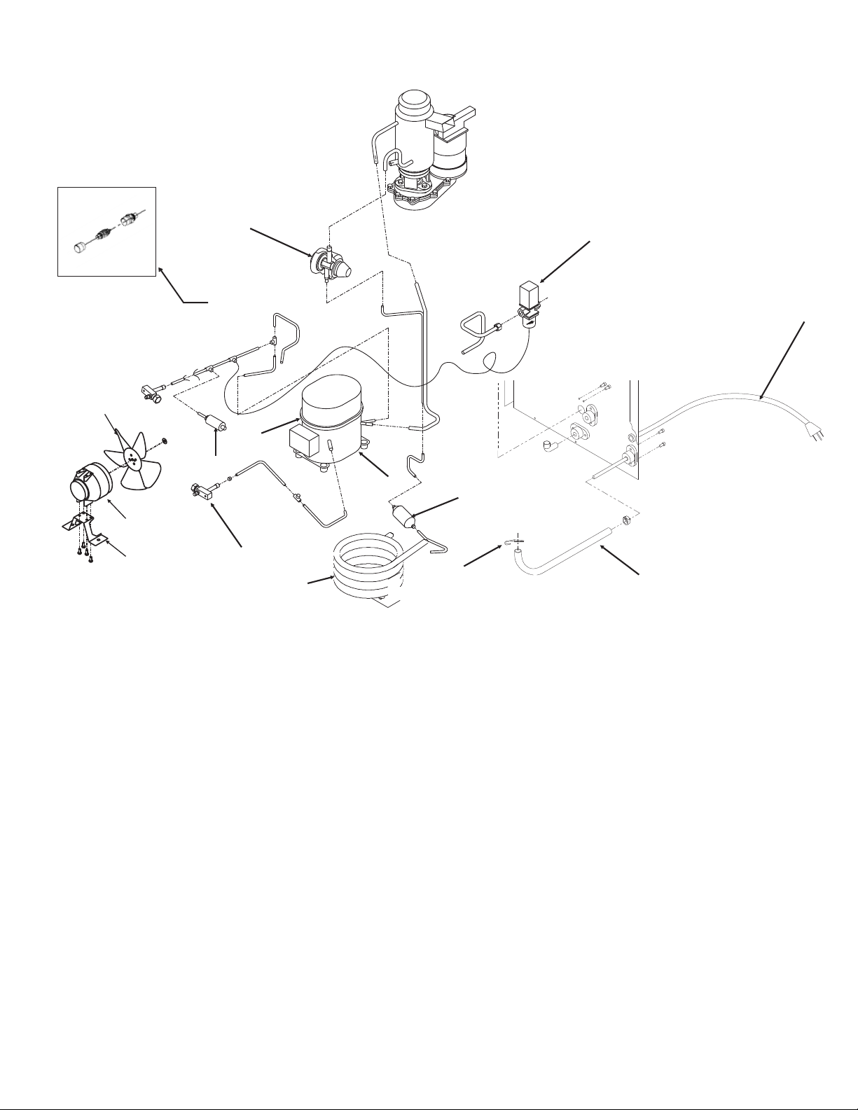
WATER COOLED REFRIGERATION
1
14
5
11
10
12
8
13
6
ITEM PART
NUMBER NUMBER DESCRIPTION
1 16-1091-21 TXV
02-3792-02 Insulation
2 11-0198-02 Water reg. valve
3 12-1638-15 Power cord 60 Hz (AC also)
12-1638-16 Power cord for 50 Hz.
4 13-0079-03 Tubing (21" req.)
5 18-8708-01 Fan blade
6 18-3707-25 A series w c condenser
18-8869-21 B & C series w c condenser
7 02-3319-01 Dryer
8 16-0832-21 Access valve
16-0832-02 Stem cap
16-0832-03 Core cap
9 03-1677-01 Screw
03-1407-07 Washer
18-2200-27 Sleeve
18-2200-28 Grommet
2
9
7
5
4
10 11-0500-21 Hi press. cut out (wc)
11 18-8918-21 60 Hz Compressor*
18-8746-26 50 Hz Compressor.*
A or B and 50 Hz C series (Tecumseh comp) parts:
18-8746-29 Start capacitor
18-8746-28 Relay
18-8746-27 Overload
18-8746-25 50 Hz Start capacitor
18-8746-24 50 Hz Relay
18-8746-23 50 Hz Overload
60 Hz C series (Danfoss compressor) parts:
18-1903-60 60 Hz relay w/overload
18-1901-60 60 Hz start capacitor
12 18-8752-21 Fan motor (water cooled)
13 A35246-001 Fan motor bracket
* Includes relay, tubing, start capacitor, and drier
Alternate Access Valve, use began 2009
14 16-1138-01 Access valve seat
16-1139-01 Core
16-1140-01 Cap
3
December 2009
Page 4
Page 5

AFE400 SERVICE PARTS
RESERVOIR AND TUBING
ITEM PART
NUMBER NUMBER DESCRIPTION
1 13-0895-01 Poly Tubing
2 obsolete Compr. sleeve
3 16-0871-01 Brass insert
4 16-0162-00 Strainer - not used after 10/97
5 02-3268-01 Clip
6 11-0296-00 Water pressure sw.
6a 16-1046-01 Plastic tube connector to switch
7 13-0859-01 Rubber plug
8 13-0674-04 Drain tube, 12" req.
9 02-2814-07 Hose clamp
10 13-0674-04 Outlet tube, 4" req.
11 16-0670-02 Tee
12 13-0674-04 Evap. inlet tube, 6" req.
13 13-0079-03 Overflow tube, 32" req.
14 02-2217-01 Reservoir & valve
15 02-2217-02 Float valve
16 16-0835-01 Male flare connector, used with
item 17
17 16-1081-01 Inlet elbow, used with male
connector and plastic tubing
18 16-1040-01 Inlet T
5
1, order 1 unit
16
17
18
1, order 3 units
2
3
4
6a
6
7
15
10
14
8
9
11
12
13
February 2009
Page 5
Page 6

AFE400 SERVICE PARTS
Evaporator
ITEM PART
NUMBER NUMBER DESCRIPTION
1 02-4404-02 Threaded cap - grey
2 03-0758-00 Screw
3 02-4535-01 Top bearing, w/thrust washer - for updated units*
4 02-4575-21 Breaker kit, includes items 1, 3, 4a, 4b,7&7a*
4a 13-0617-16 O-Ring (inside)
4b 13-0617-37 O-Ring, outside of breaker
5 02-4574-01 Auger - for updated units*
6 02-3449-20 Evaporator
7 03-1417-07 Washer
7a 03-1403-46 Screw
8 02-4599-21 Water Seal
9 02-0417-21 Lower Bearing
10 03-1505-00 Gasket
11 08-0595-01 Adapter
12 03-1405-38 Cap Screw (3)
13 03-1420-01 Cap screw
14 03-1410-04 Washer (3)
15 A29915-002 Spline Coupling
16 02-4578-01 Auger and bearing kit
Includes items 1, 2, 4, 4a, 4b, 5, 7, 7a, 8, and 9
17 19-0662-02 Top bearing grease, 13 oz tube
Note: Use about 1 oz per bearing. Lightly coat
bearing surfaces, throughly grease thrust portion
of bearing (horizontal needles).
7,
7a
9
1
2
3
4, 4a, 4b
5
6
8
15
* Updated units have new auger and top breaker and bearing.
Update available beginning Feb. 2010. Updated units have grey
cap. Non-updated units require auger kit item 16 when
replacing top bearing or auger.
12
Note: Original AFE400 had o-ring
13-0617-45 to hold foam cap halves 13-0886-01.
Also had rubber cap 13-0887-01. Not used after 2007.
11
August 2011
Page 6
10
14
13
Page 7

AFE400 SERVICE PARTS
Prior Gear Reducer A31977
ITEM PART
NUMBER NUMBER DESCRIPTION
1. 12-2059-01 Switch
2. none, part of item 3
3. A27494-001 Centrifugal Sw. Kit
4. 03-1403-77 Screw
5. A30579-001 Shaft and Actuator
6. 03-1408-36 Washer
7. 02-1503-00 Grease seal
8. 03-1408-21 Washer
9. 03-1408-04 Washer
10. 02-2445-01 Output shaft
11. 03-1515-03 Retaining ring
12. 03-1602-01 Woodruff Key
13. 02-2444-01 Output gear
14. 02-1505-00 O-ring
15. 03-0774-11 Roll pin
16. A28166-001 Gear Case
17. 03-1408-39 Washer
18. 03-1408-40 Washer shim
19. 02-2439-01 Second gear and third pinion
20. 03-1408-41 Washer
21. 03-1408-38 Washer
22. 02-2438-01 First gear and second pinion
23. A28165-021 Gear box cover
24. 02-3969-20 Grease seal
31
25. 02-1501-00 Bearing
26. 03-1408-08 Washer
27. A37707-021 60 Hz motor kit*
28. A38501-001 50 Hz motor kit*
29. A28168-001 Fan
30. A38487-001 Motor Housing with bearing
31. A32379-027 Oil
32. 02-4399-21 Complete 60 Hz Gear Motor Assembly
02-4399-24 Complete 50 Hz Gear Motor Assembly
02-4398-21 Gear reducer kit, no motor
33. A24295-001 Spacer
34 03-1408-02 Washer
35 03-1405-45 Screw
36. 13-0639-00 Grommet
* motor kit includes items 25, 26, 29 and 30.
30
29
28
27
26
25
23
20
21
22
21
20
24
19
17
36
35
16
17
18
33
34
7
18
3
1
2
4
5
8
9
10
11
12
13
9
8
14
15
MOUNTING
DETAIL
March 2007
Page 7
Page 8

AFE400 SERVICE PARTS
Gear Reducer 02-4399-21 or 02-4399-24 or 02-4398-21
ITEM PART
NUMBER NUMBER DESCRIPTION
1. 12-2059-01 Switch
2. A27494-001 Centrifugal Sw. Kit
3. 03-1403-77 Screw
4. A30579-001 Shaft and Actuator
5. part of item 2
6. 03-1408-36 Washer
7. 02-1503-00 Grease seal
8. 13-0947-01 Gasket
9. 03-1408-39 Washer
10. 03-1408-40 Washer shim
11. 02-2439-01 Second gear and third pinion
12. 03-1408-41 Washer
13. 03-1408-38 Washer
14. 02-2438-01 First gear and second pinion
15. 02-3969-20 Grease seal
16. 02-1501-00 Bearing
17. 03-1408-08 Washer
18. A37707-021 60 Hz motor kit*
19. A28168-001 Fan
20. A38487-001 Motor Housing with bearing
21. A32379-027 Oil - 16 oz bottle, use 5 oz
22. 02-4399-21 Complete 60 Hz Gear Motor
Assembly with motor
02-4399-24 Complete 50 Hz Gear Motor
Assembly with motor
02-4398-21 Gear reducer kit, no motor
23. A24295-001 Spacer
24 03-1408-02 Washer
25 03-1405-45 Screw
26. 13-0639-00 Grommet
27. 13-0941-01 Water shed
* motor kit includes items 16, 17, 19, 20
18
13
14
12
12
13
19
20
16
15
17
11
2
1
5
3
4
6
27
7
9
10
9
Included
with item 22
8
January 2011
Page 8
26
25
23
24
MOUNTING
DETAIL
Page 9

AFE400 SERVICE PARTS
CONTROL BOX
9
8
1
2
4
5
3
ITEM PART
7
6
NUMBER NUMBER DESCRIPTION
1 11-0476-21 Bin thermostat
2 03-1403-15 Machine screw
3 12-2637-01 Toggle switch, spst
4 11-0402-21 Auger delay control
5 12-0813-04 Terminal block
6 03-1404-29 Sheet metal screw
7 A35273-001 Control box cover
8 12-1213-11 Snap bushing
9 13-0727-00 Grommet
September 2011
Page 9
Page 10

AFE400 SERVICE PARTS
SCHEMATIC DIAGRAM
September 2005
Page 10
Page 11

AFE400 SERVICE PARTS
WIRING DIAGRAM
ALL CONTROLS SHOWN IN NORMAL ICE MAKING MODE
THIS UNIT MUST BE GROUNDED
September 2005
Page 11
Page 12

AFE400 SERVICE PARTS
AIR COOLED MODELS ONLY
FUSE REQ'D ONLY ON
LINE SIDE OF POWER SUPPLY
FOR 100-120 VOLT UNITS
FUSE REQ'D ON BOTH
SIDES OF POWER SUPPLY
FOR 200-240 VOLT UNITS
W
W
(CONNECTOR ON WATER
COOLED ONLY)
(CONNECTOR ON WATER COOLED ONLY)
WATERCOOLED ONLY.
(WATER COOLED ONLY)
BK
BK
FAN
MOTOR
FAN
MOTOR
LOW WATER
17-3094-01
3
2
2
1
PRESSURE
SWITCH
AUGER
DRIVE
COMPRESSOR
CENTRIFUGAL
SWITCH
MOTOR
MOTOR
BIN
HIGH PRESS
CUT OUT
THERMO
LOW WATER
PRESS CONTROL
HIGH
PRESS.
MASTER
SWITCH
POWER
SUPPLY
ALL CONTROLS SHOWN IN
NORMAL ICE MAKING MODE
POWER SUPPLY
SEE NAMEPLATE FOR PROPER
VOLTAGE REQUIREMENTS
AND MAX FUSE SIZE
THIS UNIT MUST
BE GROUNDED
RUN
START
V
BK
BK
BK
2
1
POTENTIAL RELAY
FUSITE
PROTECTOR
3
1
R
S
C
COMPRESSOR
JUNCTION BOX
START CAPACITOR
CENTRIFUGAL
LIMIT SWITCH
BK
BK
AUGER
DRIVE
MOTOR
Y
BU
Y
O
BU
BU
MASTER
BIN
THERMOSTAT
TOGGLE
SWITCH
AUGER DELAY
PRESSURE
CONTROL
PRESSURE
CONTROL
3
2
1
HIGH PRESS.
CUT OUT
TERMINAL
BOARD
BU
HIGH PRESSURE CUTOUT
(AIR COOLED ONLY)
Wiring Diagram, for air cooled units with high pressure cut out
December 2005
Page 12
Page 13

Neutral or L2
Marked 10
Mounting Clip for
Capacitor
Line or L1
Marked 3
 Loading...