

Page 1

This is the parts list for the AF300. When looking
up part numbers, always check the complete
model and serial numbers to be certain of ordering
the correct parts.
Plastic tubing is sold by the foot, order 1 unit, and
1 foot will be shipped. Order enough to cover the
length required. Lengths of tubing are listed under
the description column.
Note: The reservoir was changed in July of 1994
(date code -01Z). The two different reservoirs are
NOT interchangeable. Check the body color of the
reservoir before ordering a part.
TABLE OF CONTENTS
Cabinet . . . . . . . . . . . . . . . . . . . . . . . . . . . . . . . . . . . . . . . . . . . . . Page 2
Air cooled refrigeration . . . . . . . . . . . . . . . . . . . . . . . . . . . . . . . . . . . . . Page 3
Water cooled refrigeration . . . . . . . . . . . . . . . . . . . . . . . . . . . . . . . . . . . . Page 4
Reservoir tubing . . . . . . . . . . . . . . . . . . . . . . . . . . . . . . . . . . . . . . . . . Page 5
Evaporator . . . . . . . . . . . . . . . . . . . . . . . . . . . . . . . . . . . . . . . . . . . . Page 6
Gearmotor . . . . . . . . . . . . . . . . . . . . . . . . . . . . . . . . . . . . . . . . . . . . Page 7
Control box . . . . . . . . . . . . . . . . . . . . . . . . . . . . . . . . . . . . . . . . . . . Page 8
Wiring diagrams . . . . . . . . . . . . . . . . . . . . . . . . . . . . . . . . . . . . . . . . . Page 9
AF300 SERVICE PARTS
Page 2
AF300 SERVICE PARTS
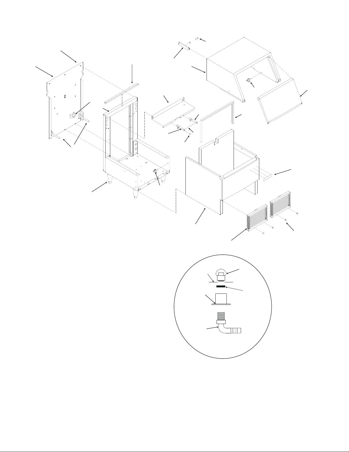
CABINET
10
11
9
14
24
8
7
ITEM PART
NUMBER NUMBER DESCRIPTION
1 A35089-020 Hood
2 A35090-032 Door
3 03-1675-01 Knob
4 03-1404-08 Screw
5 02-3153-31 Grill
21
3
12
19
13
20
1
3
12
23
6
5
22
Not Illustrated:
Scoop, part number 02-3253-01
2
18
4
6 A35088-020 Bin
7 KLP2E Leg kit
8 02-3692-21 Drain adaptor
9 A35248-001 Back panel
10 03-1404-08 Sheet metal screw
11 13-0595-01 Gasket, 21.75" req.
12 A35394-001 Bin control bracket
13-0727-00 Grommet
13 03-1531-01 Screw
14 A31828-002 Water cooled drain casting
15 02-2809-01 Drain cap
16 02-3108-01 Drain fitting
16a 02-4193-01 Flat washer, rpls o-ring
17 16-0822-01 Adaptor
18 15-0808-01 Emblem
19 19-0629-01 Door stop
June 2008
Page 2
Bin
16
17
DRAIN FITTINGS
DETAIL
15
16a
20 03-1419-09 Screw
21 A35199-001 Evaprator bracket
13-0727-00 Grommet for cap tube
22 13-0595-01 Bin gasket 36" req.
23 A35395-001 Bin control tube
24 A35452-001 Top bracket
Page 3
AF300 SERVICE PARTS
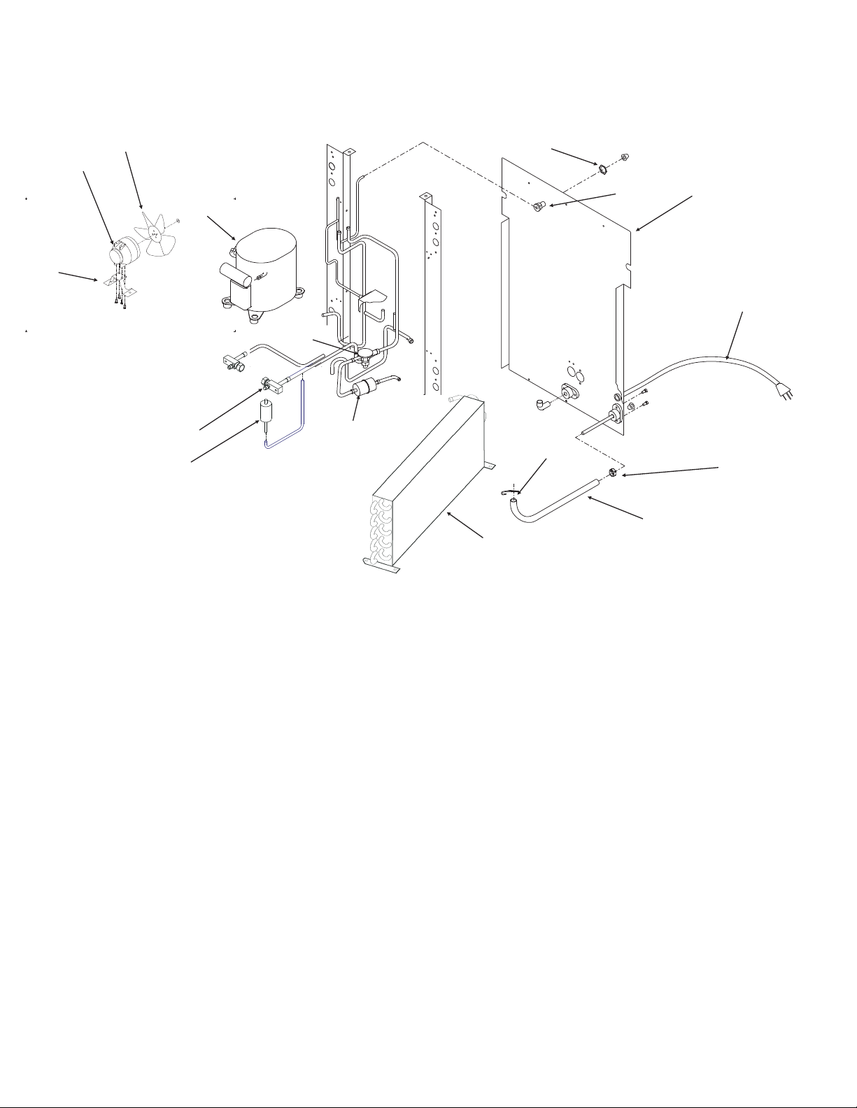
AIR COOLED REFRIGERATION
14
13
15
11
10
16
12
1
2
9
7
6
8
3
4
5
ITEM PART
NUMBER NUMBER DESCRIPTON
1 03-1394-00 Pal nut
2 A27318-001 Water inlet fitting
3 A35248-001 Back Panel
03-1404-08 Sheet metal screw
4 12-1638-14 Power cord
5 02-2814-08 Hose clamp
6 13-0674-06 Drain hose, 21.5" req.
7 02-3094-01 Hose clamp
8 18-8844-01 Air cooled condenser
02-3193-01 Air filter (not shown)
9 02-3319-01 Dryer
10 16-0832-20 Access Valve
10a 16-0832-02 Stem cap
10b 16-0832-03 Core cap
11 11-0446-26 Hi press. cut out
ITEM PART
NUMBER NUMBER DESCRIPTON
12 11-0473-21 Thermo exp. valve
A32961-020 Insulation for TXV (half)
13 12-1681-23 Fan motor
14 A35246-001 Fan motor bracket
15 18-8708-01 Fan blade
16 18-8703-20 Compressor, includes relay
overload, and start capacitor
JSS5-0050-IAA-202
18-1901-15 Start capacitor
18-1903-49 Relay
18-8703-50 Overload
Compressor Mounting Hardware:
03-1677-01 Screw
03-1407-07 Washer
18-2200-27 Sleeve
18-2200-28 Grommet
July 2007
Page 3
Page 4

AF300 SERVICE PARTS
WATER COOLED REFRIGERATION
1
17
15
16
10
13
11
12
14
9
8
7
2
3
4
5
6
ITEM PART
NUMBER NUMBER DESCRIPTON
1 03-1394-00 Pal nut
2 A27318-001 Water inlet fitting
3 A35248-001 Back Panel
03-1404-08 Sheet metal screw
4 12-1638-14 Power cord
5 02-2814-08 Hose clamp
6 13-0674-06 Drain hose, 21.5" req.
7 02-3094-01 Hose clamp
8 18-3707-25 Water cooled condenser
9 02-3319-01 Dryer
10 16-0832-20 Access valve
10a 16-0832-02 Stem cap
10b 16-0832-03 Core cap
11 11-0446-26 Hi press. cut out
12 11-0473-21 Thermo exp. valve
A32961-020 Insulation for TXV (half)
ITEM PART
NUMBER NUMBER DESCRIPTON
13 18-8703-20 Compressor, includes relay
overload, and start capacitor
JSS5-0050-IAA-202
18-1901-15 Start capacitor
18-1903-49 Relay
18-8703-50 Overload
Compressor Mounting Hardware:
03-1677-01 Screw
03-1407-07 Washer
18-2200-27 Sleeve
18-2200-28 Grommet
14 11-0424-01 Water regulating valve
15 12-1575-01 Fan motor (water cooled)
16 A35246-001 Fan motor bracket
17 18-8708-01 Fan blade
June 2007
Page 4
Page 5

AF300 SERVICE PARTS
RESERVOIR AND TUBING
ITEM PART
NUMBER NUMBER DESCRIPTION
Beige Reservoir Used Up To September 1994
1 02-2936-01 Reservoir cover
2 A32929-020 Reservoir assembly
3 no number Compression fitting, included
with item 2.
4 no number Reservoir mounting bracket.
5 13-0230-00 Rubber cap
02-2814-10 Hose clamp
6 A32907-001 Float assembly
02-3190-01 Valve seat, included with float
7 13-0840-01 Rubber plug for beige reservoir
13-0859-01 Rubber plug for clear reservoir
8 13-0674-06 Drain tube, 6" req. for beige res.
13-0674-04 Drain tube, 12" req. for clear res.
9 02-2814-08 Hose clamp
10 13-0674-06 Outlet tube, 5" req. for beige res.
13-0674-04 Outlet tube, 4" req. for clear res.
11 16-0670-02 Tee
12 13-0674-06 Evap. inlet tube 5" req. for beige res.
13-0674-04 Evap. inlet tube, 6" req. for clear res.
13 13-0674-06 Overflow tube, 30" req. for beige res
13-0079-03 Overflow tube, 32" req. for clear res.
Clear Reservoir, use began: AF300A, sn 755544-02Z
AF300W, sn 764423-03Z
14 02-2217-01 Reservoir & valve
15 02-2217-02 Float valve
1
6
2
5
Reservoir Details
9
13
9
10
9
9
11
9
12
3
4
7
8
9
15
14
“Clear” Water Reservoir
9
July 2007
Page 5
Page 6

AF300 SERVICE PARTS
Evaporator
ITEM PART
NUMBER NUMBER DESCRIPTION
1 13-0617-46 O-Ring
2 13-0887-01 Top Cap
3 03-1558-03 Retainer Ring
4 A077701-000 Cap
5 03-0758-00 Screw
6 A07699-000 Washer
7 02-0547-20 Top Bearing
8 13-0617-16 O-Ring (inside)
9 A09413-020 Breaker with Bearing*
Includes 7,8,9 and replacements for 1,2,3,4 21
10 A29480-020 Auger*
11 02-4599-21 Water Seal
12 02-0417-21 Lower Bearing
13 A29915-002 Spline Coupling
14 03-1505-00 Gasket
15 03-1410-04 Washer (3)
16 03-1420-01 Cap Screw (3)
17 08-0595-01 Adapter
18 A35410-020 Evaporator
19 03-1417-07 Washer
20 03-1403-46 Screw
21 13-0886-01 Foam cap (half)
22 13-0617-37 O-Ring, outside of breaker
21
19, 20
18
1
3
4
5
2
8, 9
8
11
6
7
22
10
* Not available, use auger kit 02-4578-01.
16
15
January 2012
Page 6
13
12
14
17
15
16
Page 7

AF300 SERVICE PARTS
GEARMOTOR
ITEM PART
NUMBER NUMBER DESCRIPTION
1. 12-2059-01 Switch
2. none, part of item 3
3. A27494-001 Centrifugal Sw. Kit
4. 03-1403-77 Screw
5. A30579-001 Shaft and Actuator
6. 03-1408-36 Washer
7. 02-1503-00 Grease seal
8. 03-1408-21 Washer**
9. 03-1408-04 Washer**
10. 02-2445-01 Output shaft**
11. 03-1515-03 Retaining ring**
12. 03-1602-01 Woodruff Key**
13. 02-2444-01 Output gear**
14. 02-1505-00 O-ring for A31977**
13-0628-00 Gasket for 02-4399
15. 03-0774-11 Roll pin**
16. A28166-001 Gear Case
17. 03-1408-39 Washer
18. 03-1408-40 Washer shim
19. 02-2439-01 Second gear and third pinion
20. 03-1408-41 Washer
21. 03-1408-38 Washer
22. 02-2438-01 First gear & second pinion
23. A28165-021 Gear box cover
24. 02-3969-20 Grease seal
25. 02-1501-00 Bearing
26. 03-1408-08 Washer
27 or 28 A37707-021 Motor kit
29. A28168-001 Fan
30. A38487-001 Motor Housing with bearing
31. A32379-021 Oil
32. 02-4399-21 Complete Gear Motor Assembly
02-4398-21 Gear reducer kit, no motor
33. A24295-001 Spacer
34 03-1408-02 Washer
35 03-1405-45 Screw
36. 13-0639-00 Grommet
* Motor kit includes 25, 26, 27, 28, 29 and 30
** Does not apply to replacement gear reducer
02-4399-01 or 02-4398-21
29
21
31
July 2007
Page 7
30
28
26
23
22
25
24
20
21
27
20
19
36
17
16
35
REMOVE
PLUG
7
18
18
17
33
34
3
1
2
4
5
8
9
10
11
12
13
9
8
14
15
MOUNTING
DETAIL
Page 8

AF300 SERVICE PARTS
CONTROL BOX
11
10
9
8
4
5
7
ITEM PART
3
1
2
2
NUMBER NUMBER DESCRIPTION
6
1 11-0476-21 Bin thermostat
2 03-1403-15 Machine screw
3 11-0420-23 Low pressure control
4 12-0426-01 Toggle switch, spst
5 12-2469-03 Contactor
6 03-1404-29 Sheet metal screw
7 no number Control box cover
8 11-0474-21 Auger delay control
9 03-1403-02 Screw
10 12-1213-11 Snap bushing
11 13-0727-00 Grommet
Not Illustrated and Not in the control box:
12 11-0296-00 Water pressure switch
June 2007
Page 8
Page 9

SCHEMATIC DIAGRAM
115/60/1
AF300 SERVICE PARTS
November 1994
Page 9
Page 10

ALL CONTROLS SHOWN IN NORMAL ICE MAKING MODE
THIS UNIT MUST BE GROUNDED
WIRING DIAGRAM
115/60/1
AF300 SERVICE PARTS
September 1994
Page 10
 Loading...