

SERVICE MANUAL
ACM 85
AC 125
AC 175
AC 225
R 134 A / R 404 A VERSIONS
Electronic cubers
with storage
MS 1000.08 REV. 03/98

Table of contents page
Specifications ACM 85
Specifications AC 125
Specifications AC 175
Specifications AC 225
GENERAL INFORMATION AND INSTALLATION
Introduction
Unpacking and Inspection
Location and levelling
Electrical connections
Water supply and drain connections
Final check list
Installation practice
OPERATING INSTRUCTIONS
Start up
Operational checks
OPERATING PRINCIPLES (How it works)
Freezing cycle
Harvest cycle
Control sequence
Component description
ADJUSTMENT, REMOVAL AND REPLACEMENT PROCEDURES
Adjustment of the cube size
Replacement of evaporator temperature sensor
Replacement of condenser temperature sensor
Replacement of ambient temperature sensor
Replacement of ice level light control
Replacement of P.C. Board
Replacement of the water pump (ACM 85)
Replacement of the water pump (AC 125 & AC 175 )
Replacement of the water pump (AC 225)
Replacement of water inlet solenoid valve
Replacement of hot gas valve coil
Replacement of water drain solenoid valve
Replacement of fan motor
Replacement of plastic curtain (ACM 85 & AC 125-175)
Replacement of spray platform and chute (ACM 85 & AC 125-175)
Replacement of spray bar (AC 225)
Replacement of drier
Replacement of hot gas valve body
Replacement of evaporator platen
Replacement of air cooled condenser
Replacement of water cooled condenser
Replacement of water regulating valve (water cooled models)
Replacement of compressor
Wiring diagram (ACM 85)
Wiring diagram (AC 125-175 & AC 225)
Service diagnosis
MAINTENANCE AND CLEANING INSTRUCTIONS
General
Icemaker
Cleaning instructions of water system
Page 01
TABLE
OF CONTENTS
1
2
4
6
8
10
10
10
11
11
11
12
13
14
18
21
22
23
27
28
28
28
28
28
28
29
29
29
29
29
29
30
30
30
30
30
30
31
31
31
32
33
34
35
38
38
39
SPECIFICATIONS
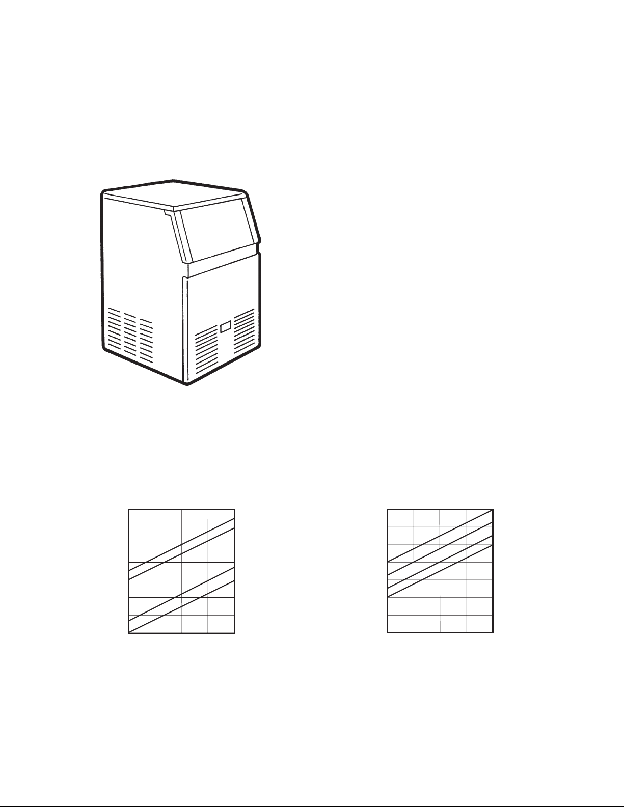
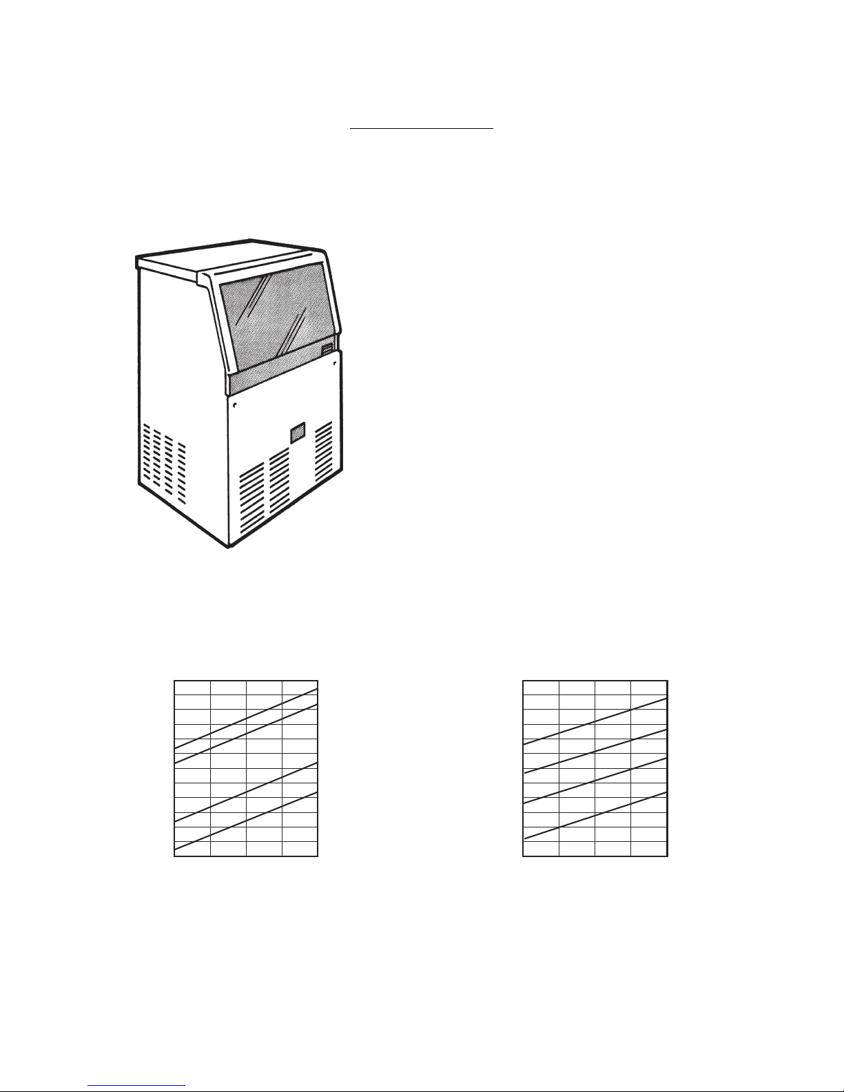
ELECTRONIC CUBER MODEL ACM 85
Important operating requirements:
MIN MAX
Air temperature 10°C (50°F) 40°C (100°¯F)
Water temperature 5°C (40°F) 40°C (100°F)
Water pressure 1 bar (14 psi) 5 bar (70 psi)
Electr. voltage
variations from
voltage rating
specified on
nameplate -10% +10%
ice making capacity
NOTE.
With the unit in “built-in” conditions, the ice production is gradually reduced in respect to the
levels shown in the graf, up to a maximum of 10% at room temperatures higher than 32°C.
The daily ice-making capacity is directly related to the condenser air inlet temperature, water
temperature and age of the machine.
To keep your SCOTSMAN CUBER at peak performance levels, periodic maintenance checks
must be carried out as indicated on page 38 of this manual.
Page 02
40
38
36
34
32
30
28
26
Kg.
32 °C
AIR COOLED MODELS
WATER TEMPERATURE
AMBIENT TEMPERA TURE
ICE PRODUCED PER 24 HRS.
°C
10
21
32
38
40
38
36
34
32
30
28
26
Kg.
°C
WATER COOLED MODELS
WATER TEMPERATURE
AMBIENT TEMPERA TURE
ICE PRODUCED PER 24 HRS.
°C
10
21
32
38
27 21 15 10 32 27 21 15 10
Basic electr. Amps. Start Amps Watts No of Wires Amp. Fuse
Page 03
SPECIFICATIONS (CONT'D)
Electr. power cons.
Kwh per 24 Hrs
230/50/1 3.2 17 500 10 3 x 1 m/m 10
2
Cubes per harvest: 24 medium
* At 15°C (60°F) water temperature
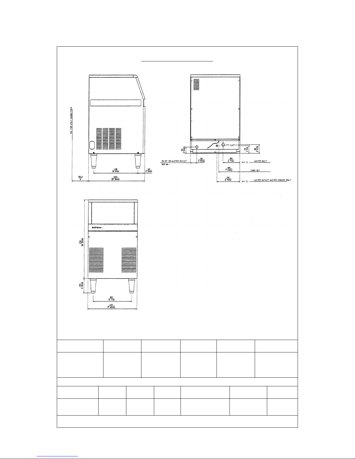
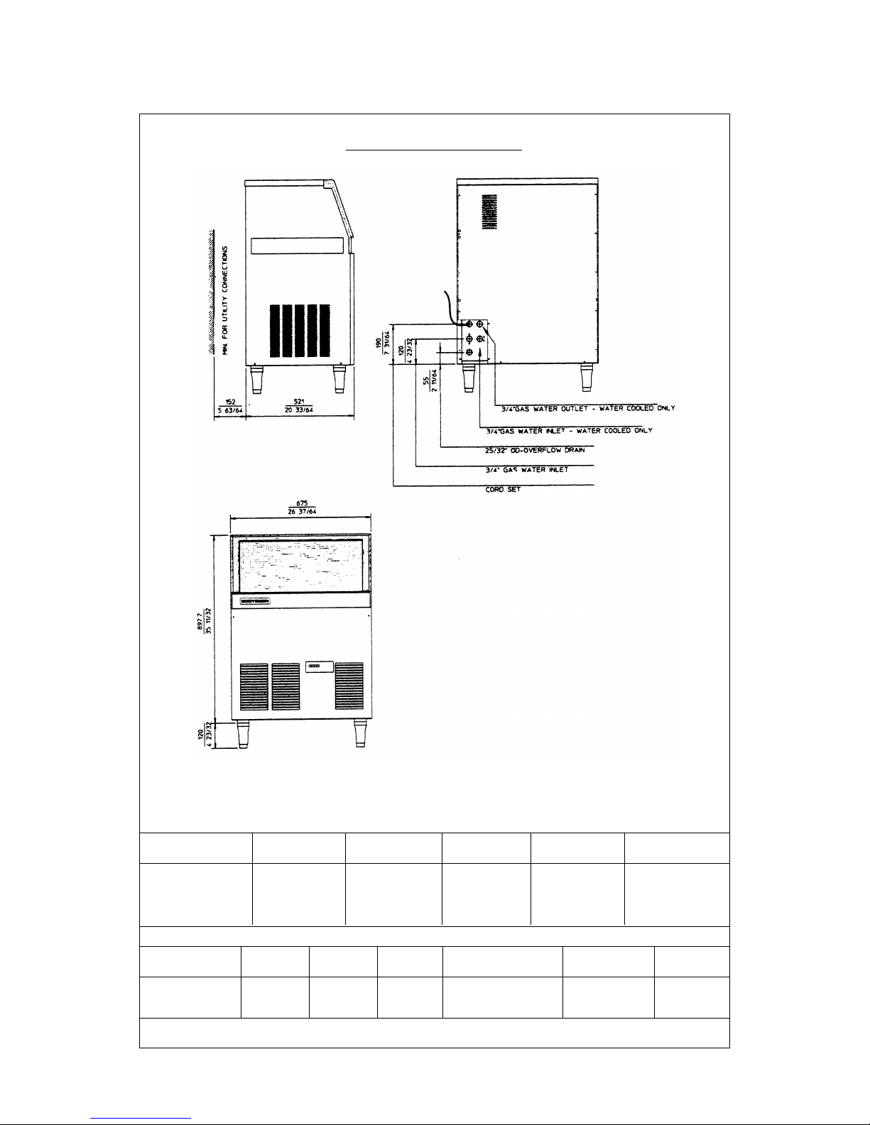
ACM 85 - CUBER MACHINE SPECIFICATION
Model Cond. Finish Comp. HP
Ice bin cap. Water requirem
Kgs. LTx24 HR
ACM 85 AS Air S/Steel 140*
3/8 14
ACM 85 WS Water S/Steel 380*
FRONT VIEW
HEIGHT (without legs) 790 mm.
HEIGHT (with legs) 930 mm.
WIDTH 457 mm.
DEPTH 523 mm.
WEIGHT 44 Kgs.
SPECIFICATIONS
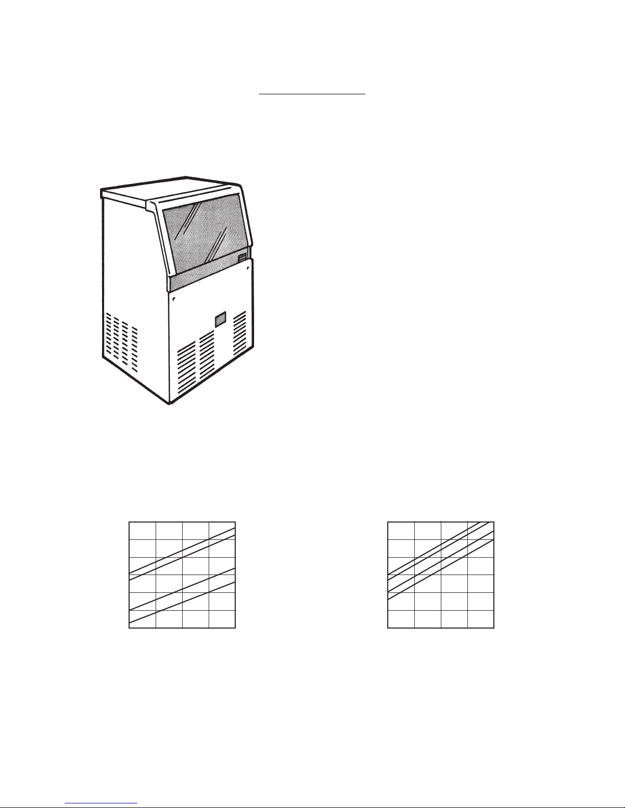
ELECTRONIC CUBER MODEL AC 125
Important operating requirements:
MIN MAX
Air temperature 10°C (50°F) 40°C (100°¯F)
Water temperature 5°C (40°F) 40°C (100°F)
Water pressure 1 bar (14 psi) 5 bar (70 psi)
Electr. voltage
variations from
voltage rating
specified on
nameplate -10% +10%
ice making capacity
NOTE.
With the unit in “built-in” conditions, the ice production is gradually reduced in respect to the
levels shown in the graf, up to a maximum of 10% at room temperatures higher than 32°C.
The daily ice-making capacity is directly related to the condenser air inlet temperature, water
temperature and age of the machine.
To keep your SCOTSMAN CUBER at peak performance levels, periodic maintenance checks
must be carried out as indicated on page 38 of this manual.
Production charts shown indicate the production of ACM models; ice production of ACL and
ACS models is 10% lower.
Page 04
75
70
65
60
55
50
45
Kg.
32 °C27 21 15 10
AIR COOLED MODELS
WATER TEMPERATURE
AMBIENT TEMPERA TURE
ICE PRODUCED PER 24 HRS.
°C
10
21
32
38
75
70
65
60
55
50
45
Kg.
°C
WATER COOLED MODELS
WATER TEMPERATURE
AMBIENT TEMPERA TURE
ICE PRODUCED PER 24 HRS.
°C
32
38
10 21
32 27 21 15 10
Basic electr. Amps. Start Amps Watts No of Wires Amp. Fuse
Page 05
SPECIFICATIONS (CONT'D)
Electr. power cons.
Kwh per 24 Hrs
230/50/1 3.8 20 670 13 3 x 1 m/m 10
Cubes per harvest: 36 large / 48 medium / 84 small
* At 15°C (60°F) water temperature
Ice bin cap. Water requirem
Kgs. LTx24 HR
AC 125 AS Air S/Steel 160*
1/2 28
AC 125 WS Water S/Steel 680*
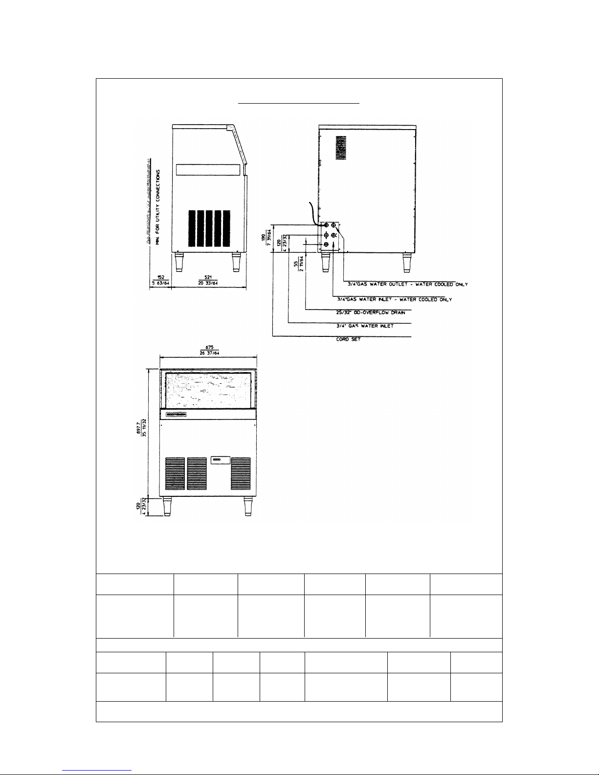
AC 125 - CUBER MACHINE SPECIFICATIONS
Model Cond. Finish Comp. HP
FRONT VIEW
HEIGHT (without legs) 900 mm.
HEIGHT (with legs) 1020 mm.
WIDTH 675 mm.
DEPTH 520 mm.
WEIGHT 75 Kgs.
2
SPECIFICATIONS
ELECTRONIC CUBER MODEL AC 175
Important operating requirements:
MIN MAX
Air temperature 10°C (50°F) 40°C (100°¯F)
Water temperature 5°C (40°F) 40°C (100°F)
Water pressure 1 bar (14 psi) 5 bar (70 psi)
Electr. voltage
variations from
voltage rating
specified on
nameplate -10% +10%
ice making capacity
NOTE.
With the unit in “built-in” conditions, the ice production is gradually reduced in respect to the
levels shown in the graf, up to a maximum of 10% at room temperatures higher than 32°C.
The daily ice-making capacity is directly related to the condenser air inlet temperature, water
temperature and age of the machine.
To keep your SCOTSMAN CUBER at peak performance levels, periodic maintenance checks
must be carried out as indicated on page 38 of this manual.
Production charts shown indicate the production of ACM models; ice production of ACL and
ACS models is 10% lower.
Page 06
87,5
Kg.
32 10 °C
AIR COOLED MODELS
WATER TEMPERATURE
AMBIENT TEMPERA TURE
ICE PRODUCED PER 24 HRS.
°C
10
21
32
38
WATER COOLED MODELS
10
21
27 21 15
85
82,5
80
77,5
75
72,5
70
67,5
65
62,5
60
57,5
87,5
Kg.
32 10 °C
WATER TEMPERATURE
AMBIENT TEMPERA TURE
ICE PRODUCED PER 24 HRS.
°C
10
21
10
21
32
38
27 21 15
85
82,5
80
77,5
75
72,5
70
67,5
65
90
92,5
95
Basic electr. Amps. Start Amps Watts No of Wires Amp. Fuse
SPECIFICATIONS (CONT'D)
Electr. power cons.
Kwh per 24 Hrs
230/50/1 5.3 29 850 18 3 x 1 m/m 16
Cubes per harvest: 36 large / 48 medium
* At 15°C (60°F) water temperature
Ice bin cap. Water requirem
Kgs. LTx24 HR
AC 175 AS Air S/Steel 0160*
3/4 28
AC 175 WS Water S/Steel 1000*
AC 175 - CUBER MACHINE SPECIFICATIONS
Model Cond. Finish Comp. HP
FRONT VIEW
HEIGHT (without legs) 900 mm.
HEIGHT (with legs) 1020 mm.
WIDTH 675 mm.
DEPTH 520 mm.
WEIGHT 75 Kgs.
Page 07
2
SPECIFICATIONS
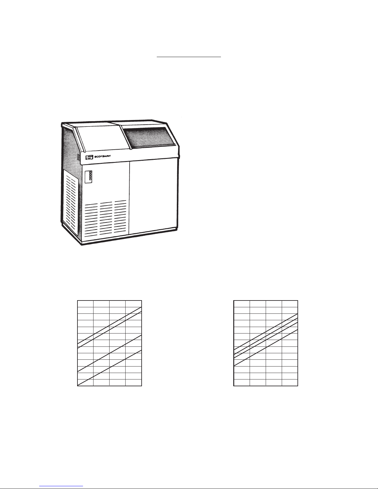
ELECTRONIC CUBER MODEL AC 225
Important operating requirements:
MIN MAX
Air temperature 10°C (50°F) 40°C (100°¯F)
Water temperature 5°C (40°F) 40°C (100°F)
Water pressure 1 bar (14 psi) 5 bar (70 psi)
Electr. voltage
variations from
voltage rating
specified on
nameplate -10% +10%
ice making capacity
NOTE.
With the unit in “built-in” conditions, the ice production is gradually reduced in respect to the
levels shown in the graf, up to a maximum of 10% at room temperatures higher than 32°C.
The daily ice-making capacity is directly related to the condenser air inlet temperature, water
temperature and age of the machine.
To keep your SCOTSMAN CUBER at peak performance levels, periodic maintenance checks
must be carried out as indicated on page 38 of this manual.
Production charts shown indicate the production of ACM models; ice production of ACL and
ACS models is 10% lower.
Page 08
150
145
140
135
130
125
120
115
110
105
100
95
90
85
Kg.
32
°
C
AIR COOLED MODELS
WATER TEMPERATURE
AMBIENT TEMPERA TURE
ICE PRODUCED PER 24 HRS.
°
C
10
21
32
38
WATER COOLED MODELS
27 21 15 10
160
155
150
145
140
135
130
125
120
115
110
105
100
95
Kg.
32
°
C
WATER TEMPERATURE
AMBIENT TEMPERA TURE
ICE PRODUCED PER 24 HRS.
°
C
10
21
32
38
27 21 15 10
Basic electr. Amps. Start Amps Watts No of Wires Amp. Fuse
Page 09
SPECIFICATIONS (CONT'D)
Electr. power cons.
Kwh per 24 Hrs
230/50/1 5.3 29 1100 22 3 x 1.5 m/m 16
Cubes per harvest: 72 large / 102 medium / 198 small.
* At 15°C (60°F) water temperature
2
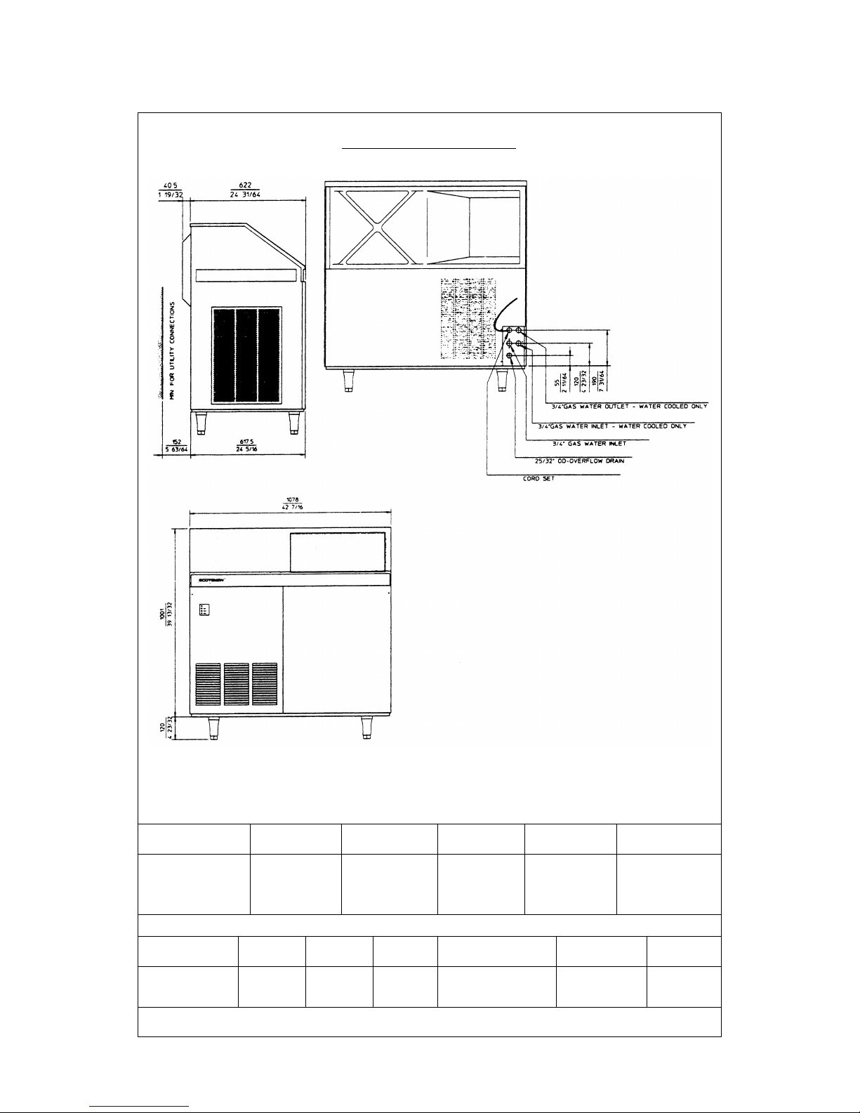
FRONT VIEW
HEIGHT (without legs) 1006 mm.
HEIGHT (with legs) 1126 mm.
WIDTH 1078 mm.
DEPTH 660 mm.
WEIGHT 115 Kgs.
AC 225 - CUBER MACHINE SPECIFICATIONS
Model Cond. Finish Comp. HP
Ice bin cap. Water requirem
Kgs. LTx24 HR
AC 225 AS Air S/Steel 0250*
170
AC 225 WS Water S/Steel 1500*

A. INTRODUCTION
This manual provides the specifications and the
step-by-step procedures for the installation, startup and operation, maintenance and cleaning for
the SCOTSMAN ACM 85, AC 125, AC 175 and
AC 225 icemakers.
The Electronic Cubers are quality designed,
engineered and manufactured.
Their ice making systems are thoroughly tested
providing the utmost in flexibility to fit the needs
of a particular user.
NOTE. To retain the safety and performance
built into this icemaker, it is important that
installation and maintenance be conducted
in the manner outlined in this manual.
B. UNPACKING AND INSPECTION
1. Call your authorized SCOTSMAN Distributor
or Dealer for proper installation.
2. Visually inspect the exterior of the packing
and skid. Any severe damage noted should be
reported to the delivering carrier and a concealed
damage claim form filled in subjet to inspection of
the contents with the carrier’s representative
present.
3. a) Cut and remove the plastic strip securing
the carton box to the skid.
b) Remove the packing nails securing the
carton box to the skid.
c) Cut open the top of the carton and remove
the polystyre protection sheet.
d) Pull out the polystyre post from the corners
and then remove the carton.
4. Remove the front and (if any) the rear
panels of the unit and inspect for any concealed
damage. Notify carrier of your claim for the
concealed damage as steted in step 2 above.
5. Remove all internal support packing and
masking tape. (Leg package is located in the
storage bin compartment).
6. Check that refrigerant lines do not rub
against or tuch other lines or surfaces, and that
the fan blade moves freely.
7. Check that the compressor fits snugly onto
all its mounting pads.
8. Use clean damp cloth to wipe the surfaces
inside the storage bin and the outside of the
cabinet.
GENERAL INFORMATION AND INSTALLATION
Page 010
9. See data plate on the rear side of the unit
and check that local main voltage corresponds
with the voltage specified on it.
CAUTION. Incorrect voltage supplied to
the icemaker will void your parts
replacement program.
10. Remove the manufacturer’s registration
card from the inside of the User Manual and fillin all parts including: Model and Serial Number
taken from the data plate.
Forward the completed self-addressed
registration card to the SCOTSMAN Europe
Frimont factory.
11. If necessary fit the four legs into their seats
on the machine base and adjust them to the
desired level.
C. LOCATION AND LEVELING
WARNING. This Ice Cuber is designed for
indoor installation only. Extended periods
of operation at temperature exceeding
the following limitations will constitute
misuse under the terms of the SCOTSMAN
Manufacturer’s Limited Warranty resulting
in LOSS or warranty coverage.
1. Position the unit in the selected permanent
location.
Criteria for selection of location include:
a) Minimum room temperature 10°C (50°F)
and maximum room temperature 40°C (100°F).
b) Water inlet temperatures: minimum 5°C
(40°F) and maximum 40°C (100°F).
c) Well ventilated location for air cooled
models. Clean the air cooled condenser at
frequent intervals.
d) Service access: adequate space must be
left for all service connections through the rear of
the ice maker. A minimum clearance of 15 cm
(6") must be left at the sides of the unit for routing
cooling air drawn into and exhausted out of the
compartment to maintain proper condensing
operation of air cooled models.
2. Level the unit in both the left to right and
front to rear directions.

D. ELECTRICAL CONNECTIONS
See data plate for current requirements to
determine wire size to be used for electrical
connections. All SCOTSMAN icemakers require
a solid earth wire.
All SCOTSMAN ice machines are supplied from
the factory completely pre-wired and require only
electrical power connections to wire cord provided
at the rear of the unit.
Make sure that the ice machine is connected to
its own circuit and individually fused (see data
plate for fuse size).
The maximum allowable voltage variation should
not exceed -10% and + 10% of the data plate
rating. Low voltage can cause faulty functioning
and may be responsible for serious damage to
the overload switch and motor windings.
NOTE. All external wiring should conform to
national, state and local standards and
regulations.
Check voltage on the line and the ice maker’s
data plate before connecting the unit.
E. WATER SUPPLY AND DRAIN
CONNECTIONS
GENERAL
When choosing the water supply for the ice cuber
consideration should be given to:
a) Length of run
b) Water clarity and purity
c) Adequate water supply pressure
Since water is the most important single ingredient
in producting ice you cannot emphasize too
much the three items listed above.
Low water pressure, below 1 bar may cause
malfunction of the ice maker unit.
Water containing excessive minerals will tend to
produce cloudy coloured ice cubes, plus scale
build-up on parts of the water system.
WATER SUPPLY
Connect the 3/4" male fitting of the solenoid
water inlet valve, using the flexible tube supplied
to the cold water supply line with regular plumbing
fitting and a shut-off valve installed in an
accessible position between the water supply
line and the unit.
If water contains a high level of impurities, it is
advisable to consider the installation of an
appropriate water filter or conditioner.
Page 11
WATER SUPPLY - WATER COOLED MODELS
The water cooled versions of SCOTSMAN Ice
Makers require two separate inlet water supplies,
one for water sprayed for making the ice cubes
and the other for the water cooled condenser.
Connect the 3/4" male fitting of the water inlet,
using the flexible tube supplied to the cold water
supply line with regular plumbing fitting and a
shut-off valve installed in an accessible position
between the water supply line and the unit.
WATER DRAIN
The recommended drain tube is a plastic or
flexible tube with 18 mm (3/4") I.D. which runs to
an open trapped and vented drain. When the
drain is a long run, allow 3 cm pitch per meter
(1/4" pitch per foot)
A vent at the unit drain connection is also required
for proper sump drainage.
WATER DRAIN - WATER COOLED MODELS
Connect the 3/4" male fitting of the condenser
water drain, utilizing a second flexible tubing to
the open trapped and vented drain.
NOTE. The water supply and the water drain
must be installed to conform with the local
code. In some case a licensed plumber and/
or a plumbing permit is required.
F. FINAL CHECK LIST
1. Is the unit level? (IMPORTANT)
2. Have all the electrical and plumbing
connections been made, and is the water supply
shut-off valve open?
3. Has the voltage been tested and checked
against the data plate rating?
4. Have the bin liner and cabinet been wiped
clean?
5. Have the bolts holding the compressor down
been checked to ensure that the compressor is
snugly fitted onto the mounting pads?
6. Has the owner/user been given the User
Manual and been instructed on the importance of
periodic maintenance checks?
7. Has the Manufacturer’s registration card
been filled in properly? Check for correct model
and serial number against the serial plate and
mail the registration card to the factory.
8. Check all refrigerant lines and conduit
lines to guard against vibrations and possible
failure.
9. Is the unit in a room where ambient
temperatures are within a minimum of 10°C
(50¯F) even in winter months?
10. Is there at least a 15 cm (6") clearance
Page 12
around the unit for proper air circulation?
11. Has the water supply pressure been
checked to ensure a water pressure of at least 1
bar (14 psi).
12. Has the owner been given the name and the
phone number of the authorized SCOTSMAN
Service Agency serving him?
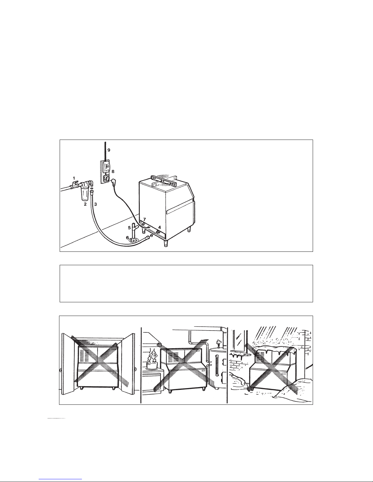
WARNING. This icemaker is not designed for outdoor installation and will not function
in ambient temperatures below 10°C (50°F) or above 40°C (100°F).
This icemaker will malfunction with water temperatures below 5°C (40°F) or above
40°C (100°F).
1. Hand shut-off valve
2. Water filter
3. Water supply line (flexible hose)
4. 3/4" male fitting
5. Vented drain
6. Open trapped vented drain
7. Drain fitting
8. Main switch
9. Power line
G. INSTALLATION PRACTICE
 Loading...