

Page 1

Page 1
Page 1
SERVICE MANUAL
MANUALE DI SERVIZIO
ACM 25
VERSIONE R 134 A / R 404 A
Home ice cuber
Fabbricatore di
ghiaccio a cubetti
domestico
090088.41 - REV. 03/2002
Page 2

Page 2
Page 2
TABLE OF CONTENTS PAGE
TO THE USER 3
USER’S INFORMATIONS
- INTRODUCTION 4
DESCRIPTION
• Sealed Refrigeration System 4
• Self contained Storage Bin 4
• Removable water reservoir 4
SPECIFICATIONS 5
OPERATIONS BEFORE UNIT
START-UP 6
OPERATING INSTRUCTIONS
• Start-up 6
• Cleaning and Care 8
PRINCIPLE OF OPERATIONS
• Freezing cycle 10
• Harvest cycle 10
INDICE PAGINA
PER L’UTILIZZATORE 20
INFORMAZIONI PER L’UTILIZZATORE
- INTRODUZIONE 21
DESCRIZIONE
• Sistema refrigerante 21
• Contenitore del ghiaccio 21
• Bacinella dell’acqua amovibile 21
SPECIFICHE TECNICHE 22
OPERAZIONI DA EFFETTUARE
PRIMA DELL’AVVIAMENTO 23
ISTRUZIONI DI FUNZIONAMENTO
• Avviamento 23
• Pulizia e manutenzione 25
PRINCIPIO DI FUNZIONAMENTO
• Ciclo di congelamento 27
• Ciclo di sbrinamento 27
SERVICEMAN’S INFORMATIONS
- GENERAL 11
• Service Diagnosis 11
• Wiring Diagram 13
• Adjustment & Removal & Replacement
• Procedure 14
PARTS ILLUSTRATIONS AND
PARTS LIST ACCESSORIES 15
COMPRESSOR AND ELECTRIC
COMPONENTS CHART 19
INFORMAZIONI TECNICHE
- PREMESSA 28
• Servizio analisi 28
• Schema elettrico 30
• Procedure per la rimozione e la
• sostituzione dei vari componenti 31
ILLUSTRAZIONI ED ELENCHI
DELLE PARTI DI RICAMBIO ED
ACCESSORI 32
COMPONENTI DEL COMPRESSORE
ED ELETTRICI 36
Page 3
Page 3
TO THE USER
Page 3
Your SCOTSMAN model ACM 25 Ice Maker is a
product carefully engineered and quality
constructed to provide you with many years of
faithful performance and a minimum of
maintenance costs.
Produced by the world’s leading manufacturer of
automatic ice making equipments, your
SCOTSMAN ICE CUBE MAKER incorporates
the same reliable systems already proven over
years of actual operation by thousands of users.
Many of you will have an opportunity to see and
use clear, slow melting SCOTSMAN CUBERS
for the first time.
You will quickly compare the clear, glass-like
quality of your Scotsman Cubes to the type
produced by your home refrigerator, freezer.
By comparison, cubes made in trays in your
refrigerator are very white or cloudy, they also
melt faster than clear ice.
Take the time now to review this manual and you
will see why Scotsman Cubes are solid and
clearer than ice cubes of your refrigerator.
No installation is required
Easy access for service is provided by the prompt
removal of the front panel and/or the cabinet.
Page 4
Page 4
Page 4
USER'S INFORMATIONS
INTRODUCTION
This manual provides the specifications and the
step-by-step procedures for the start-up and
operation and, the maintenance and cleaning for
the SCOTSMAN Model ACM 25 Automatic Ice
Cube Maker.
The ACM 25 Automatic Cubers are quality
designed, engineered and constructed and
throughly, tested ice making and ice storage
systems, providing the utmost in flexibility to fit
the needs of particular users.
Separate sections detail more specifically:
General Informations & Start-up Operation;
Principles of Operation; Adjustment and Removal
and Replacement Procedures; Maintenance &
Cleaning Instructions; Service Diagnosis; Wiring
Diagrams; and the illustrated Assemblies, Parts
List & Accessories.
One of the outstanding features of this series of
cubers is the easy way for starting it up.
Since it does not require any plumbing connection,
it can be placed in any location and put in
operation.
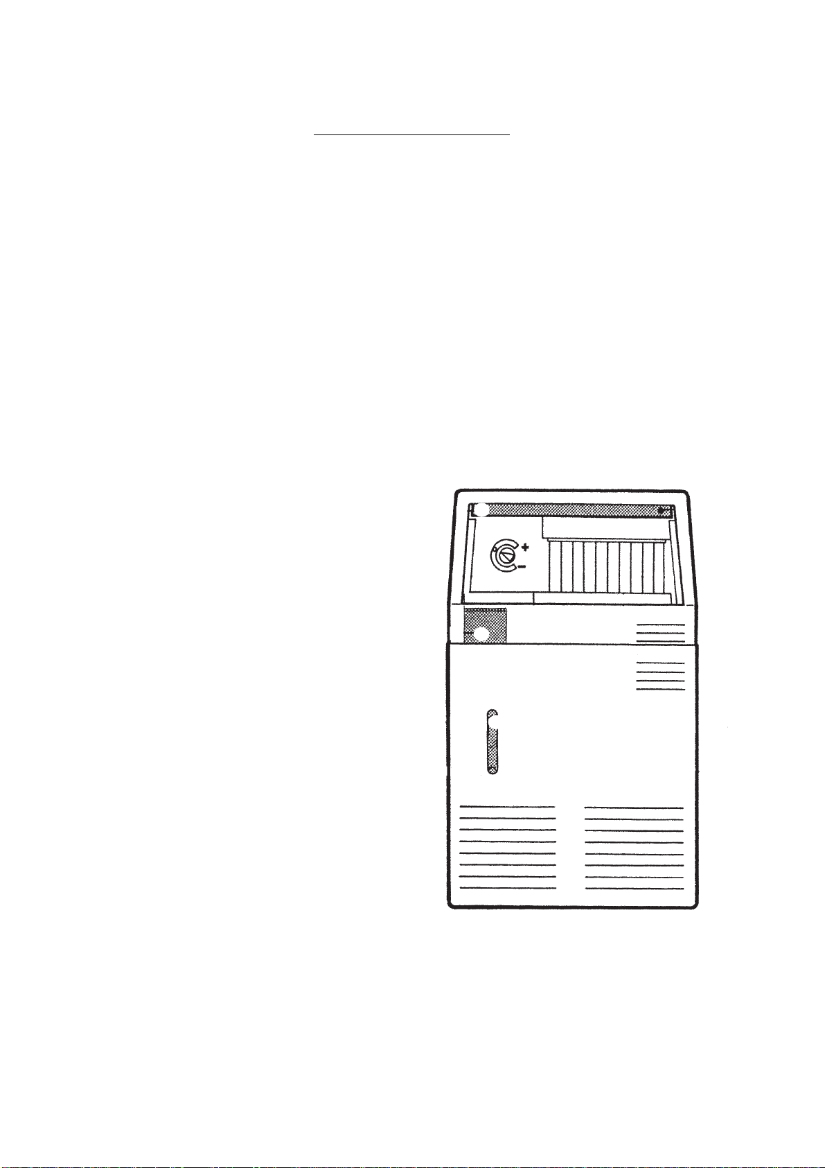
REMOVABLE WATER RESERVOIR
The most exclusive feature of the ACM 25 consists
in having a removable water sump reservoir. It
can be easily removed at any time to be washed
clean.
A water level indicator is provided on the front of
the reservoir alloving prompt visual inspection of
water level into reservoir.
A special funnel in comunication with the water
reservoir allows prompt and easy filling of water
reservoir itself without the need to remove it.
∂
∏
∑
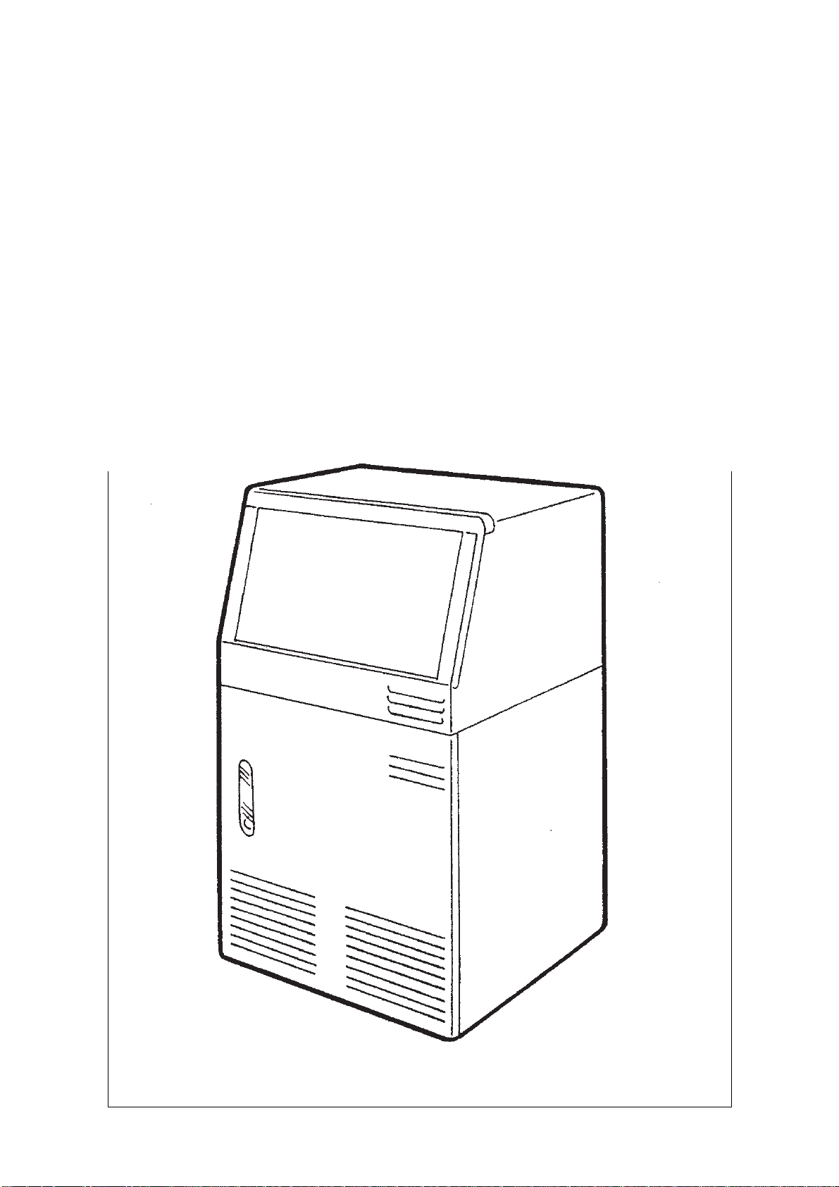
DESCRIPTION
An attractive compact cabinet of textured plastic
with an almond enamel finish, makes the styling
of the ACM 25 very handsome allowing it to be in
harmony with many interior decors. The easy
removable front panel provides immediate access
to the water reservoir and to the electromechanical components.
SEALED REFRIGERATION SYSTEM
The compressor is fully hermetic and its motor is
internally spring-mounted to ensure quiet and
efficient operation of the Ice Maker.
The refrigerant circuit is entirely sealed to prevent
mishandling and refrigerant leaks.
SELF CONTAINED STORAGE BIN
The ACM 25 ICE MAKER stores its own ice
supply in a properly insulated ice storage bin.
A sensing bulb of a thermostat keeps automatic
control of the stored ice cubes level.
A sliding (recessing) plastic door located in the
upper front of the cabinet gives ample access to
the storage bin.
π
∫
bin recessing door
∂
ice storage bin
∑
water vessel
∏
water level indicator
π
front panel
∫
Page 5
Page 5
Page 5
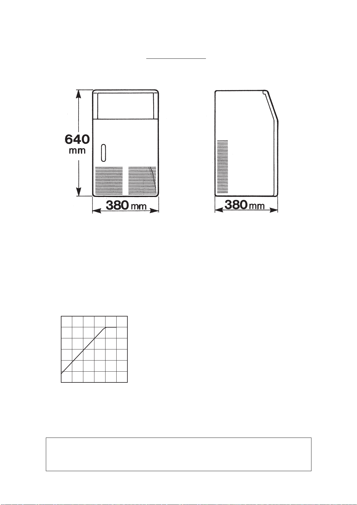
SPECIFICATIONS
AIR COOLED MODELS
Kg.
11
10
9
8
7
6
ICE PRODUCED PER 24 HRS.
5
35 30 525 20 15 10
AMBIENT TEMPERATURE
• Dimensions = m/m 380 wide-380 deep-640 high
• Weight = 29 kg (64 Ibs.)
• Cabinet = Plastic
• Finish = Enamel
• Color = Almond
• Storage bin = ABS
• Door = Sliding (recess)
• Power Requirements = 230 Volts, 50 Hz, 1 Phase
• Power Consumption = 4,5 Kwh x 24 HRS
• Wire Size = 1 m/m
2
• Fuse Size = 6 Amps
• Compressor = 1/5 HP
• Refrigerant metering
device = Capillary
• Refrigerant Charge = 220 grms FREON, R 134 A
• Harvest Means = Hot gas
o
°C
• Cubes per harvest = 8
• Storage bin capacity = 3.5 Kgs. (7.7 Ibs.)
• Water reservoir capacity = 4 liters (1.1 gl.)
°C
°F
NOTE.
When machine is “built-in” at ambient temperature of 32°C (90°F) indicated ice capacity
decreases about 10%.
To keep your SCOTSMAN CUBER performing at its maximum capacity, it is necessary to perform
periodic maintenance as outlined on page 8 of this manual.
Page 6
Page 6
Page 6
OPERATIONS TO PERFORM
BEFORE UNIT START-UP
1) After unpacking the unit, visually inspect its
exterior and make sure it does not show any
severe damage.
2) Remove Lower Compartment Panel and
inspect for concealed damage; then check if fan
blades move freely, and if compressor is snug on
all mounting pads.
OPERATING INSTRUCTIONS
START-UP
1) Locate on left side, in storage bin
compartment the funnel for pouring the water.
2) Through this funnel pour in unit water
reservoir 4 liters of fresh potable water.
3) Open the bin door and remove any
wrappings or adhesive tape that may be inside,
as well as the instruction card attached to the
control knob.
4) Use clean damp cloth or disposable paper
wiper to wipe clean the interior surface of ice
storage bin.
5) Place ice maker in its selected permanent
location and make sure that it is properly levelled.
NOTICE:
shall include:
a) Minimum room temperature 10°C
(50 degrees F); and maximum room temperature 35°C (95 degrees F)
b) Well ventiled location for efficient air
removal around the unit and maintain proper
condensing operation.
c) Service Access i.e. adequate space for
prompt service inspections.
6) Check that the location source voltage
corresponds with the voltage specified on the
nameplate of the unit.
Prior consideration for location site
3) Check to see through the water level glass
the water level obtained. (Must not exceed the
maximum level line and not below minimum level
line).
WARNING: The location power source
must have a solid earth wire connection.
Page 7
Page 7
Page 7
4) Plug the electric cable into the appropriate
socket. Make sure that the indicator on the control
knob is pointing to the “white dot”. The machine
is now working and the first cooling cycle can
begin.
5) The first freezing cycle will last about 35
minutes. During this time, make sure that the
plastic curtain that covers the water spray system
hangs down loose and no excessive water is
passing through, make sure to eliminate
eventually noises and vibration sources.
6) After about 35 minutes of operation, the
first ice cubes harvest takes place.
7) During the harvest cycle, which lasts about
3 minutes, the hot gas, circulating through the
evaporator serpentine, defrosts the ice cubes up
to the point that they are released from their mold
cups and drop into the storage bin.
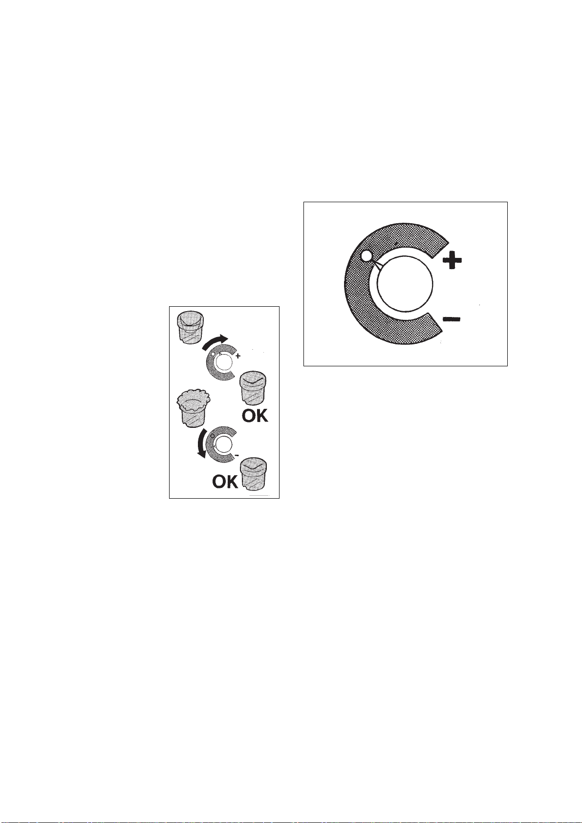
8) If the tem-
perature of the
room in which the
machine is place
is below 20°C, the
cubes will tend to
be partly hollowed out (see fig.
on right).
If, on the other
hand, the room
temperature is
above 30°C the
cubes produced
will have a jagged
rim of ice around
the crown.
9) If it is thought necessary, the above
situations can be remedied by, in the first case,
turning the control knob indicator (as little or as
much as is required) to the left of the white
marker and, in the second case, turning the knob
to the right. It should, however, be remembered
that if the room temperature returns later to the
20 ÷ 30°C range, the knob indicator must once
again be turned to point to the white dot. (see fig.
below).
10) The ice maker will automatically stop when
the ice cubes in this storage bin compartment
cover the sensing bulb of the bin thermostat and
will automatically start when the same sensing
bulb will be cleared from the ice.
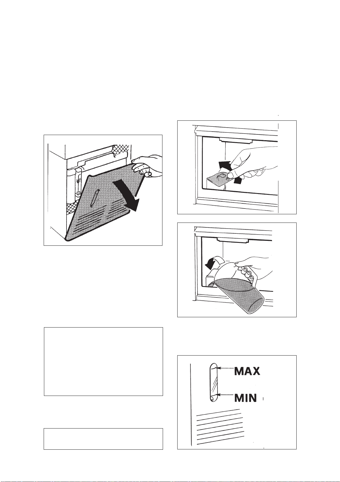
11) Remember to fill up the water reservoir
before the water level in it goes below the minimum
level line of the indicator.
In any case, if for some reason the machine is left
running for a short time without water, no serious
harm will be caused.
Page 8
Page 8
CLEANING AND CARE
WARNING - Before proceeding with
any cleaning operation make sure that
the power line of the unit is disconnected.
WATER RESERVOIR AND STORAGE
BIN LINER
All commercial units that make or contain edible
produces, require a frequent throught sanitation
of all their parts that are in contact with the
produces.
It is recommendable, therefore, to perform the
cleaning and disinfecting operation once a week
as per the following indications.
Page 8
- Remove all ice cubes deposited in ice storage
bin if there are any.
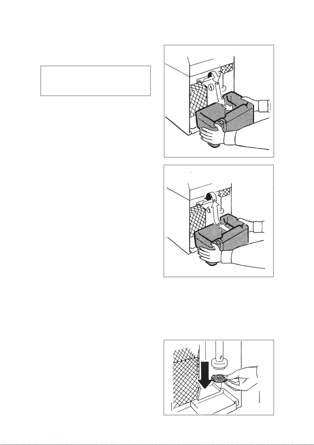
- Remove the front lower panel by pulling it
from its upper edge and locate the water
reservoir.
Place one hand under the reservoir in order to
hold it and with the other grab the hooked front
edge.
- Slightly move the reservoir upward until it is
loose, than lower and tilt it a bit while
drawing out (try to avoid the pump body in
doing this).
- Make this reservoir empty and then place it back
in the unit.
- In a separate plastic pan, prepare a solution with
two liters of water and one full spoon of chlorine
water (hypochlorite).
- Pour the prepared solution into the storage bin
compartment than wipe clean its interior,
meanwhile the solution flows down into the
reservoir.
- Connect the power line and put in operation the
unit for few minutes. The bleaching solution will
be circulated by the pump through the water
pipes and nozzles.
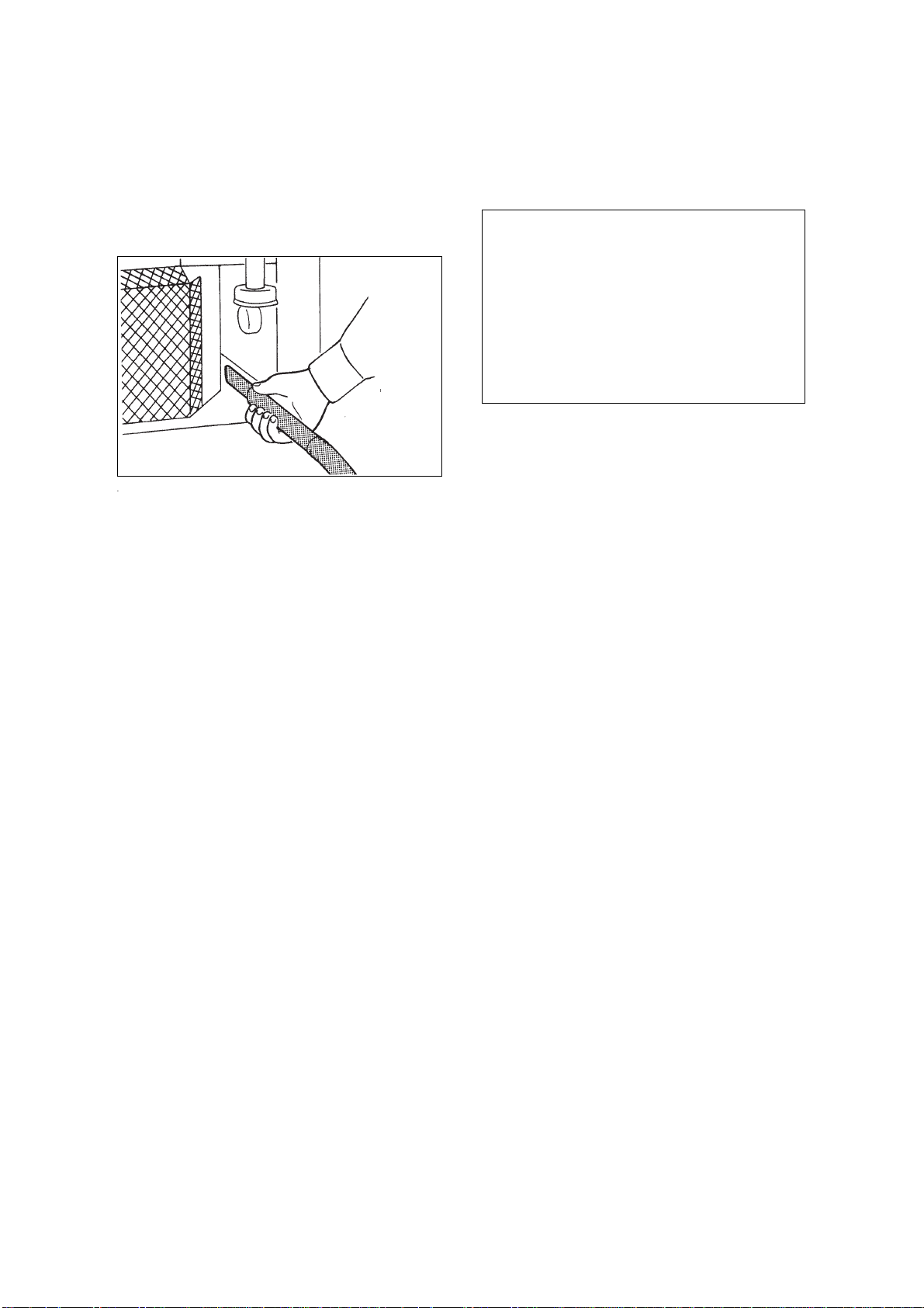
PUMP INLET SCREEN
While the water reservoir is removed, it is
recommendable to clean the water pump inlet
screen.
Pull it down with gentle pressure and wash it
clean under a stream of tap water. Once the
screen is properly cleaned reposition it in its
original place on the pump body.
- Disconnect the power line, remove again the
plastic reservoir, make it empty then re-fit it in its
place.
- Pour through the funnel the necessary quantity
of new fresh water until the maximum water
level in the water reservoir is reached.
- The until is now sanitized and can resume
normal operations.
Page 9
Page 9
Page 9
AIR COOLED CONDENSER
It is very important to clean the condenser
regularly. A dirty or blocked condenser, will
drastically reduce ice production.
Use a vacuum cleaner to remove dust from the
front of the condenser.
CABINET EXTERIOR
Clean with warm water. Do not apply wax.
Note.
When cleaning the floor in the immediate front the unit, try to do not move much
dust that could be easily sucked inside the
units through the panel louvers.
Eventually, for few seconds, you can place
in front of the louvers a piece of paper or
cardboard to prevent that the brushed
dust panetrates into the machine
compartment.
Page 10
Page 10
Page 10
PRINCIPLE OF OPERATION
In the Scotsman ACM 25, the water to make ice
is continually moved or circulated by a small
electric pump that sprays the water under gentle
pressure through the two spray jets into the eight
inverted cube molds.
Part of the water that hits the cold refrigerated
molds freezes, building gradually into full ice
cubes bell shaped.
FREEZING CYCLE (How it works)
The hot gas refrigerant, pumped and discharged
by the compressor, passes through the condenser
where the fan blowing air causes the changing of
it into liquid.
The liquid line takes the refrigerant from the
condenser to the capillary tube. During the travel
into the capillary tube, the liquid refrigerant looses
gradually its temperature and pressure, then it
reaches the evaporator coils.
Because of the water sprayed against the
evaporator molds and coil, the liquid refrigerant
senses the heat of this water and starts boiling,
changing, as a consequence, from liquid into
vapor state.
The vapor refrigerant is sucked back to the
compressor through the suction line.
The freezing cycle is controlled by a temperature
control which determines as well the length of the
cycle and consequently the size of the ice cube.
During this phase, the contact point of the temperature control maintains closed the circuit of the
water pump which constantly sprays the water
under the evaporator mold cups up to the point
that the ice cubes reach their full size.
∑
∑
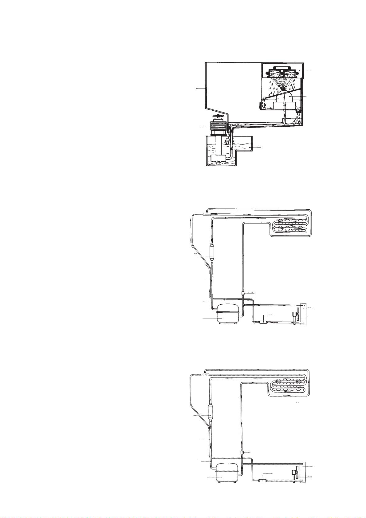
WATER CIRCUIT
∂
∏
π
① EVAPORATOR
≠ BIN
∫
③ SPRAY TUBE
④ WATER PUMP
∞ WATER RESERVOIR
FREEZING CYCLE
∂
① EVAPORATOR
≠ ACCUMULATOR
③ CAPILLARY TUBE
④ SUCTION LINE
∞ COMPRESSOR
± HOT GAS SOLENOID
∏
❻
± VALVE CLOSED
≤ CONDENSER
≥ FAN MOTOR
⑨ DRIER
π
❼
∫
❾
Ω
HARVEST CYCLE (How it works)
As soon as the temperature control senses the
temperature in the evaporator corresponding to
the full size cubes, the contact moves to close the
circuit of the Hot Gas Valve Coil and consequently
to open the circuit of the water pump which
momentarily stops.
The hot gas refrigerant discharged by the
compressor is now diverted through the opened
hot gas valve to the evaporator coil.
The hot gas circulares through the evaporator
coil raising the temperature around the cube
cups sufficiently to release the ice cubes.
The released ice cubes drop by gravity into the
storage bin.
The temperature control bulb, due to the warm
temperature in the evaporator moves again the
contact de-energizing the hot gas valve and
energizing the water circulating pump starting a
new freezing cycle.
∑
π
∏
HARVEST CYCLE
❻
❾
∂
① EVAPORATOR
≠ ACCUMULATOR
③ CAPILLARY TUBE
④ SUCTION LINE
∞ COMPRESSOR
± HOT GAS SOLENOID
± VALVE OPENED
≤ CONDENSER
≥ FAN MOTOR
⑨ DRIER
❼
Ω∫
Page 11
Page 11
Page 11
SERVICEMAN’S INFORMATIONS
GENERAL
perature.
It gradually pulls down to 7 atm at the end of the
Models ACM 25 Ice Cube Makers have been
designed for little service and maintenance
requirements.
Average head pressure is 10 atm at the start-up
of the freezing cycle at 21°C ambient tem-
cycle.
Suction pressure at the start-up of the freezing
cycle will be around 3 atm then it pulls down
gradually to approximately 0 atm at the end of
freezing cycle.
SERVICE ANALYSIS
The following Service Analysis Section is for use in aiding the serviceman in diagnosing a particular
problem for pin-pointing the area in which the problem lies, thus an ever available reference for proper
corrective action.
SYMPTOM POSSIBLE CAUSE CORRECTION
Machine does not make ice. Fuse in Power Line Blown. Check fuses in the house fuse
box. Other loads on the same
line may have caused fuse
to blow. Use a 10 amp circuit
and fuse.
Water reservoir empty. Re-fill water reservoir.
Temp. control out of setting. Check for proper setting.
Wiring broken or connection off. Check electrical circuitry.
Compressor does not run. Any of the following may be
Water pump not operating. Clean or replace pump.
Bin thermostat not operating Check thermostat by warming
correctly. with hand and cooling with ice
Restricted Capillary Tube. Purge and recharge.
Moisture and air in system. Purge - recharge - replace drier.
Shortage of refrigerant. Charge unit properly.
Low ice capacity. High Room Temperature. Provide ventilation to the unit.
High head pressure. Dirty condenser. Clean.
the cause. Starting relay,
overload, or defective compressor.
cube. Replace if necessary.
Decrease temperature as much
as possible.
Cubes too large. Cube Size Control set Check and adjust for proper
improperly. operation.
Page 12

Page 12
SYMPTOM POSSIBLE CAUSE CORRECTION
Cubes cloudy. Spray jets Dirty. Clean.
Page 12
Shortage of Water. Check water level in water
Dirty water supply, accumulator Wipe clean water reservoir
of dirty in water system. and re-fill with new fresh water.
Cubes too small. Shortage of water. Check water level in reservoir.
Cube size control set Check and adjust for proper
improperly. operation.
Water leaking from pump Check clamp and hoses.
hoses. Replace if necessary.
Compressor cycles Low voltage. Minimum voltasge to be 10%
intermittently. Iess than normal rating.
Air in the system. Purge and recharge.
Poor harvest cycle. Too short defrost time. Check temperature control -
Hot gas not passing through Check hot gas valve coil,
valve. replace if necessary.
reservoir and re-fill.
Clean water pump screen.
replace if necessary.
Shortage of refrigerant. Charge unit properly.
Ice cubes too big. Set control knob correct shape
of ice cubes.
Page 13

Page 13
Page 13
WIRING DIAGRAM
A BLUE
M BROWN
N BLACK
G-V YELLOW-GREEN
PUMP MOTOR
BIN. TEMP. CONTROL
FAN MOTOR
MOTOR SOLENOID VALVE
6
MOTOR COMPRESSOR
THERMOSTAT
THERMOSTAT
6
BIN. TEMP. CONTROL
2
4
2
4
COMPRESSOR MOTOR
HOT SOLENOID VALVE
PUMP MOTOR
FAN MOTOR
Page 14

Page 14
Page 14
REMOVAL & REPLACEMENT PROCEDURE
WARNING: DISCONNECT THE ELECTRICAL SUPPLY BEFORE PERFORMING
ANY OF THE FOLLOWING OPERATIONS
Cabinet Removal
1. Remove lower panel by pulling forwand at
both top corners.
2. Remove water reservoir.
3. Disconnect the electrical cord and pass it
through the rear side of the cabinet into the unit
compartment.
4. Unloose and remove the two screws
secuting the front door trim to the side walls of
cabinet.
5. Through the interior of the compressor
compartment reach the three screws securing
the cabinet to the chassis and unloose them.
(See indicating arrows).
6. Remove the bottom drip tray.
7. Remove the cabinet by pulling it forward
from the rear side.
7. Locate the thermostat bulb on the evaporator
and push it out from its well.
8. The control is now entirely removed.
9. Re-assemble the new control by
proceeding on reserve.
NOTE:
Seal both the ends of bulb holder
after the introduction of the new evaporator
thermostat capillary tube to avoid that some
water freezes inside.
Bin thermostat replacement
1. Follow step 1 thru 7 for cabinet removal.
2. Follow step 1 thru 4 for temperature control
replacement.
3. Unloose and remove the nut securing the
bin control to the panel.
4. Remove the end of bin control capillary
tube from the interior of the bin.
5. Remove the spade connection from the
Temp. Control.
6. The control is now completely free.
Proceed to re-assemble acting on reserve.
Temperature control replacement
(Evaporator)
1. Follow step 1 thru 7 for cabinet removal.
2. Remove temperature control knob by pulling
it.
3. Unloose the screw securing the control box
panel.
4. Pull forward the control box panel.
5. Unloose and remove the nut securing the
temperature control to the panel.
6. Remove the spade connections from the
control.
Water pump Replacement
1. Follow step 1 thru 7 for cabinet removal.
2. Remove the screw which holds the water
pump in place.
3. Remove the two water pump electrical
leads.
4. Remove the hose from pump bottom
housing.
5. Lift out the pump.
6. To small the replacement pump, follow
previous steps in reverse.
Page 15

Page 15
THE PARTS ILLUSTRATIONS AND PARTS LIST
CONTROL PANEL ASSY
Page 15
④
±
≤
≥
Pos. Part. N. Description
4 630070.04 Terminal board
6 620264.10 Evaporator thermostat
7 660321.01 Panel
8 620263.00 Bin control
Page 16

Page 16
FRONT - VIEW
Page 16
Pos. Part. N. Description
3 620433.00 Water pump assy
18 650330.00 Plug
22 660321.00 Control panel
24 784169.03 Curtain
25 660330.00 Funnel cover
Page 17

Page 17
SIDE - VIEW
Page 17
Pos. Part. N. Description
44 741049.02 Evaporator cover
46 650331.01 Insulation
47 660326.00 Cabinet assy
49 660340.02 Evap. bulb holder
660386.00 Clip
50 783130.00 Evap housing
51 640093.00 Seal ring
52 660320.00 Water spray tray
53 610139.00 Plastic hose
(pump to spray system)
54 660336.00 Cover
57 660325.00 Water drip tray
58 781284.00 Bin door
59 782053.00 Ice storage bin
60 660339.00 Bulb holder
* Not shown
Pos. Part. N. Description
61 781285.00 Front lower panel
62 793114.00 Water reservoir assy
63 781335.00 Reservoir holder
65 784234.00 Evaporator platen assy
66 784252.02 Suction accumulator
67* 660359.00 Funnel insert
68 660335.00 Upper separator
69 660343.00 Lower separator
70 660338.00 Rubber fitting
71 660337.00 Sight glass
72* 783141.00 Reservoir cover
660424.00 Reservoir cover - Pump
73 660341.00 Rubber plug
Page 18

Page 18
COMPRESSOR & CONDENSING UNIT
Page 18
Pos. Part. N. Description
1 670097.08 Compressor cpl. Electrolux
670066.09 Compressor cpl. U.H.
2 620306.48 Hot gas valve coil
620306.14 Hot gas valve body
3 620419.00 Fan motor only
7 620058.65 Protector for Electrolux
620058.64 Protector for U.H.
Pos. Part. N. Description
8 620057.35 Relay for Electrolux
620057.32 Relay for U.H.
23 630003.05 Dryer
35 620285.00 Condenser
36 781283.00 Chassis assy
Page 19

Page 19
Page 19
ACM 25 - COMPRESSOR AND ELECTRIC COMPONENTS CHART
Model Volts Compr. Model Compr. Cpl.
ACM 25-2 230/60/1 U.H. AE Z4425Y 670066.08 620057.40 620058.74 620167.45
ACM 25-6 230/50/1 Cubigel GL 80PB 670097.08 620057.35 620058.65 –
U.H. AE Z4425Y 670066.09 620057.32 620058.64 –
Model Water pump
ACM 25-2 620306.48 620433.01 620419.00
ACM 25-6 620306.48 620433.00 620419.00
Hot gas valve Fan motor
coil only
Compr. Compr. Start
relay protector Capacitor
Page 20

Page 20
PER L’UTILIZZATORE
Pagina 20
Page 20
Il vostro fabbricatore di ghiaccio SCOTSMAN
modello ACM 25 è un prodotto accuratamente
progettato e costruito per assicurarvi anni di
ottime prestazioni con costi di esercizio e manutenzione minimi.
Costruita dalla maggiore industria mondiale del
settore, la vostra SCOTSMAN impiega lo stesso
principio per la fabbricazione del ghiaccio lungamente sperimentato su decine di migliaia di
apparecchi in funzione in tutte le parti del
mondo.
Molti di voi avranno per la prima volta l’opportunità di vedere ed utilizzare i cubetti di ghiaccio
SCOTSMAN caratterizzati da una elevata solidità e trasparenza e, molto importante, da una
lenta fusione, fattori non riscontrabili in quelli
formati nel vostro frigorifero domestico che in
genere sono opachi e di rapida fusione.
Vorremmo ora suggerirvi di dedicare un po’ del
vostro tempo alla lettura del presente manuale;
potrete così sincerarvi delle ragioni per cui i
cubetti di ghiaccio SCOTSMAN sono molto
più trasparenti e solidi di quelli del vostro
frigorifero.
Non è richiesto nessun allacciamento idraulico
Togliendo il pannello frontale e/o l’intero mantello si può facilmente accedere ai vari componenti
del fabbricatore di ghiaccio ACM 25.
Page 21

Pagina 21
Page 21
INTRODUZIONE
Page 21
INFORMAZIONI PER L’UTILIZZATORE
Il presente manuale è stato emesso per fornire
tutte le informazioni utili onde agevolare il compito di chi è preposto all’avviamento ed alla
riparazione dei fabbricatori di ghiaccio; infatti,
oltre alle specifiche tecniche contiene numerose
indicazioni per il posizionamento, l’avviamento,
il funzionamento, la manutenzione e la pulizia
del fabbricatore di ghiaccio a cubetti SCOTSMAN
modello ACM 25.
I fabbricatori di ghiaccio a cubetti ACM 25 sono
stati progettati e costruiti con un elevato standard
qualitativo; essi vengono collaudati interamente
per diverse ore e sono in grado di assicurare il
massimo rendimento relativamente ad ogni particolare uso e situazione.
Un notevole numero di informazioni è esposto
minuziosamente nei diversi capitoli, che sono:
Informazioni Generali; Avviamento e Marcia;
Principi di Funzionamento; Procedure per la
Regolazione, la Rimozione e la Sostituzione;
Schemi Elettrici; Istruzioni per la Manutenzione e
la Pulizia e le illustrazioni dei componenti e Parti
di Ricambio.
Una delle caratteristiche principali di questa serie di apparecchi consiste nel loro avviamento
estremamente semplice.
Non richiedendo alcun collegamento idraulico,
possono essere collocati e messi in funzione in
qualsiasi luogo.
Lo sportello scorrevole, posto nella parte frontale
superiore del mobile, permette un agevole accesso al contenitore stesso.
BACINELLA DELL’ACQUA AMOVIBILE
Caratteristica esclusiva dell’ACM 25 consiste
nell’avere una bacinella contenente l’acqua, agevolmente rimovibile dall’apparecchio per facilitare la sua pulizia periodica.
L’indicatore di livello, situato nella parte frontale,
permette una pronta verifica del livello dell’acqua.
Uno speciale imbuto, posto nell’angolo sinistro
del contenitore del ghiaccio, consente il ripristino
del livello d’acqua nella bacinella senza il bisogno di rimuovere la stessa.
∂
∏
∑
DESCRIZIONE
Grazie ad un mobile di design sobrio e gradevole, in plastica smaltata color avorio, il fabbricatore
di ghiaccio a cubetti ACM 25 può essere armoniosamente inserito in qualunque ambiente. Il
pannello frontale, di facile rimozione, permette
un immediato accesso alla bacinella dell’acqua
ed ai componenti elettrici dell’apparecchio.
SISTEMA REFRIGERANTE
Il compressore impiegato è del tipo ermetico,
quindi particolarmente efficace e silenzioso durante il funzionamento; il circuito frigorifero è
completamente ermetico onde prevenire delle
perdite di refrigerante dal medesimo.
CONTENITORE DEL GHIACCIO
Il fabbricatore di ghiaccio ACM 25 è in grado di
stivare la propria produzione in un contenitore
propriamente isolato.
Il bulbo sensibile del termostato contenitore
mantiene automaticamente il livello del ghiaccio
in esso stivato.
π
∫
∂
∑
∏
π
∫
Page 22

Page 22
SPECIFICHE TECNICHE
Pagina 22
Page 22
RAFFREDDAMENTO AD ARIA
Kg.
11
10
9
8
7
6
GHIACCIO PRODOTTO IN 24 ORE
5
35 30 525 20 15 10
TEMPERATURA AMBIENTE
• Dimensioni = larghezza mm. 380
== profondità-380 altezza-640
• Peso = 29 kg.
• Mobile = Plastica
• Finitura = Verniciato
• Colore = Avorio
• Contenitore ghiaccio = ABS
• Sportello = Scorrevole
• Alimentazione elettrica = 230/50/1
• Consumo di energia
elettrica = 4,5 Kwh x 24 ore
• Dimensione cavo di
alimentazione = 1 mm
2
• Fusibile = 6 Amps
• Compressore = 1/5 HP
• Dispositivo espansione
refrigerante = Tubo capillare
• Carica refrigerante = 220 gr. FREON R 134 A
• Scongelamento = Tramite gas caldo
• Cubetti per ciclo = 8
• Capacità contenitore
o
°C
ghiaccio = 3.5 Kg.
• Capacità bacinella acqua = 4 litri
°C
°F
NOTA
. Con l’apparecchio incassato la produzione di ghiaccio è ridotta rispetto a quanto indica il
diagramma, sino a raggiungere un massimo del 10% a temperatura ambiente superiore a 32°C.
Per mantenere la produzione del vostro fabbricatore di ghiaccio a cubetti al massimo della sua
condizione è necessario eseguire la manutenzione periodica come illustrato a pagina 25 di questo
manuale.
Page 23

Pagina 23
Page 23
Page 23
OPERAZIONI DA EFFETTUARE
PRIMA DELL’AVVIAMENTO
1) Sballare l’apparecchio e controllare che
non abbia subito alcun danno durante il trasporto.
2) Togliere il pannello frontale inferiore ed
asportare il serbatoio acqua per meglio controllare l’interno dell’apparecchio; assicurarsi che il
ventilatore giri liberamente e che il compressore
sia ben posizionato sui supporti.
ISTRUZIONI DI
FUNZIONAMENTO
AVVIAMENTO
1) Localizzare nella parte sinistra del contenitore l’imbuto di riempimento acqua alla macchina.
2) Versare attraverso l’imbuto 4 litri di acqua
potabile.
3) Aprire lo sportello del contenitore e togliere
eventuali involucri o nastri adesivi all’interno
dello stesso, nonchè il cartellino d’istruzioni fissato sul volantino di comando.
4) Pulire l’interno del contenitore con un panno umido e pulito.
5) Sistemare l’apparecchio nella sua posizione definitiva ed assicurarsi che sia ben livellato.
NOTA:
nare la macchina occorre tener presente
che:
a) Minima temperatura ambiente
b) Luogo ben ventilato per una efficiente
c) Spazio adeguato per una facile ispezione
6) Accertarsi che l’alimentazione elettrica disponibile corrisponda a quanto indicato sulla
targhetta dell’apparecchio.
nella scelta del luogo in cui posizio-
10°C (50°F);
Massima temperatura ambiente
35°C (95°F)
ventilazione intorno all’apparecchio e
quindi corretto funzionamento del condensatore.
dell’apparecchio e delle sue parti.
3) Controllare attraverso l’indicatore di livello
la posizione raggiunta dall’acqua. (Non deve superare il massimo nè essere inferiore al minimo).
ATTENZIONE: la presa elettrica di collegamento all’apparecchio deve essere
provvista di un buon collegamento a terra.
Page 24

Page 24
Pagina 24
Page 24
4) Inserire la spina nella relativa presa di corrente. Accertarsi che il volantino di comando
abbia l’indicatore posto in corrispondenza del
“punto bianco”. L’apparecchio entra in funzione
ed ha inizio il primo ciclo di refrigerazione.
5) Per il primo completamento di questo ciclo
occorreranno circa 30/35 minuti. Durante questo
tempo accertarsi che la tendina paraspruzzi sia
ben posizionata e non lasci passare acqua in
eccesso. Eliminare eventuali cause di rumori o
vibrazioni.
6) Dopo circa 30/35 minuti si avrà il primo ciclo
di sbrinamento che consentirà il distacco e la
caduta dei primi 8 cubetti.
7) Il distacco e la conseguente caduta degli 8
cubetti è causata dal gas caldo pompato dal
compressore che, circolando nella serpentina
dell’evaporatore, scalda le sedi dei cubetti provocando quindi un leggero scioglimento dei
cubetti stessi che, non essendo più trattentuti
dall’effetto congelante, cadono nel contenitore di
raccolta.
8) Se la tempe-
ratura del locale
in cui è posto l’apparecchio è inferiore a 20°C, i
cubetti prodotti
possono avere un
incavo pronunciato al loro intervento (Vedi figura a lato).
Se invece la temperatura ambiente sarà superiore
a 30°C i cubetti
prodotti tenderanno ad avere
delle frastagliature di ghiaccio
attorno alla corona.
9) Chi lo ritenesse necessario, potrebbe migliorare le sopra illustrate situazioni di cubetti,
portando, nel primo caso, l’indicatore del volantino di comando più o meno leggermente a
sinistra del punto bianco di riferimento, nel secondo caso più o meno leggermente a destra.
Occorre però tener presente che, qualora la
temperatura ambiente rientrasse entro i
20 ÷ 30°C, l’indicatore del volantino andrà ripor-
tato in corrispondenza del punto bianco (Vedi
illustrazione sotto).
10) L’apparecchio si fermerà automaticamente quando il contenitore sarà pieno di ghiaccio ed
i cubetti toccheranno il bulbo del termostato
contenitore, e si rimetterà automaticamente in
funzione una volta prelevato il ghiaccio.
11) Ricordarsi di riempire di acqua il contenitore dell’apparecchio ogni qualvolta il livello dell’acqua sarà inferiore al minimo .
Comunque, se l’apparecchio verrà lasciato in
funzione senz’acqua per brevi periodi, per dimenticanza od altro, non avverrà alcunchè di
grave.
Page 25

Pagina 25
Page 25
PULIZIA E MANUTENZIONE
ATTENZIONE. Prima di procedere a qualsiasi operazione di pulizia accertarsi che
la corrente elettrica dell’apparecchio sia
staccata.
BACINELLA CONTENITORE ACQUA E
RISERVA GHIACCIO
Tutte le apparecchiature commerciali che producono o preservano dei prodotti commestibili richiedono una pulizia ed una disinfezione frequente delle loro parti che sono in contatto con il
prodotto.
Per tale motivo si raccomanda di effettuare sul
produttore di ghiaccio una pulizia e disinfezione
settimanale secondo le indicazioni seguenti:
- Togliere tutto il ghiaccio eventuale contenuto
nella riserva di ghiaccio.
- Togliere il pannello frontale inferiore tirandolo
dal bordo superiore e localizzare la bacinella
acqua.
- Mettere una mano sotto alla bacinella per sostenerla e con l’altra prendere la sua parte
superiore.
- Muovere lentamente la bacinella verso l’alto
finché sia liberata dall’incastro, quindi verso il
basso piegandola leggermente in avanti mentre la si estrae. (Evitare di toccare il corpo della
pompa durante questa operazione).
-Svuotare completamente la bacinella e
rimetterala di nuovo al suo posto.
- In un recipiente a parte preparare una soluzione di due litri di acqua ed un cucchiaio di
varechina.
- Versare tale soluzione così preparata nella
riserva di ghiaccio e pulirne bene il suo interno
nel mentre la soluzione discende nella bacinella sottostante.
- Ricollegare la corrente elettrica all’apparecchio
e mettere in funzione la macchina per pochi
minuti. La soluzione pulente verrà fatta circolare dalla pompa attraverso i tubi dell’acqua e gli
spruzzatori.
- Staccare la corrente elettrica all’apparecchio,
togliere di nuovo la bacinella contenitore acqua, svuotarla completamente e rimetterla nella sua posizione originale.
- Versare attraverso l’imbuto di riempimento la
quantità di acqua potabile necessaria al riempimento del contenitore fino alla posizione massima indicata sull’indicatore di livello.
- L’apparecchio è adesso disinfettato e può riprendere il suo normale funzionamento.
Page 25
FILTRO ENTRATA POMPA
Quando si procede alla pulizia della bacinella è
consigliabile pulire anche il filtro di entrata della
pompa.
Togliere il filtro dal corpo pompa mediante una
leggera pressione e pulirlo sotto un getto di
acqua corrente. Indi rimetterlo nella sua posizione originale.
Page 26

Page 26
Pagina 26
Page 26
CONDENSATORE AD ARIA
E’ molto importante pulire periodicamente il condensatore ad aria. Un condensatore sporco o
bloccato riduce drasticamente la produzione di
ghiaccio. Usare un aspirapolvere per togliere lo
sporco accumulatosi sulla parte frontale del condensatore.
ESTERNO DELL'APPARECCHIO
Pulire con acqua tiepida. Non usare cera.
NOTA.
Quando si pulisce il pavimento nelle
immediate vicinanze dell’apparecchio, fare
in modo di non sollevare molta polvere che
potrebbe facilmente essere aspirata all’interno dell’apparecchio attraverso le feritoie del
pannello frontale.
Eventualmente per pochi secondi si potrebbe mettere davanti alle feritoie un foglio di
carta o di cartone per evitare che la polvere
sollevata possa penetrare all’interno
dell’apparechio.
Page 27

Page 27Pagina 27
Page 27
PRINCIPIO DI
FUNZIONAMENTO
Nel fabbricatore di ghiaccio SCOTSMAN modello ACM 25 l’acqua usata per la produzione del
ghiaccio è tenuta costantemente in movimento
tramite una pompa elettrica che spruzza l’acqua
a pressione moderata, attraverso gli spruzzatori,
all’interno dei bicchierini rovesciati
dall’evaporatore.
CICLO DI CONGELAMENTO
Il refrigerante allo stato gassoso pompato dal
compressore passa attraverso il condensatore
dove si trasforma in refrigerante allo stato liquido. La linea del liquido permette al refrigerante di
fluire dal condensatore al tubo capillare attraverso il filtro deumidificatore. Durante il passaggio
attraverso il tubo capillare il refrigerante allo stato
liquido perde gradualmente la sua pressione e
temperatura raggiungendo successivamente la
serpentina dell’evaporatore. L’acqua spruzzata
nei bicchierini rovesciati dell’evaporatore cede
del calore al refrigerante circolante all’interno
della serpentina, causandone l’evaporazione
quindi cambiandone di conseguenza il suo stato
fisico che da liquido diviene vapore.
Il refrigerante allo stato vaporoso dopo essere
passato attraverso l’accumulatore viene aspirato nuovamente dal compressore tramite la linea
di aspirazione.
Il ciclo di congelamento è regolato da un controllo della temperatura (termostato evaporatore)
che determina la durata dello stesso e di conseguenza la dimensione dei cubetti.
Durante il ciclo di congelamento i contatti elettrici
del termostato evaporatore mantengono chiuso
il circuito elettrico della pompa la quale spruzza
costantemente l’acqua nei bicchierini rovesciati
fino a che i cubetti di ghiaccio raggiungono le
giuste dimensioni.
∑
∑
CIRCUITO IDRAULICO
∂
∏
π
① EVAPORATORE
∫
CICLO DI CONGELAMENTO
≠ CONTENITORE
③ SPRUZZATORE
④ POMPA
∞ BACINELLA ACQUA
∂
∏
❻
π
❼
∫
❾
Ω
CICLO DI SBRINAMENTO
Al momento in cui il termostato evaporatore
sente la temperatura corrispondente ai cubetti di
ghiaccio di dimensione piena, i contatti dello
stesso cambiano posizione chiudendo il circuito
della bobina del gas caldo ed allo stesso tempo
si aprono i circuiti della pompa e del ventilatore i
quali cessano di funzionare.
Il refrigerante allo stato gassoso, pompato dal
compressore, è ora dirottato dalla valvola del gas
caldo aperta, direttamente alla serpentina
dell’evaporatore, seguendo il percorso più diretto cioè non passando attraverso il condensatore.
Il gas caldo, che circola all’interno della serpentina
dell’evaporatore, fa aumentare la temperatura
dei bicchierini facendo quindi distaccare i cubetti
di ghiaccio dai medesimi.
I cubetti staccatisi cadono per gravità sopra lo
scivolo da dove vengono convogliati all’interno
del contenitore del ghiaccio.
Grazie al fluire del gas caldo nella serpentina
dell’evaporatore, la temperatura dello stesso sale
e conseguentemente sale anche la temperatura
del bulbo sensibile del termostato evaporatore il
CICLO DI SBRINAMENTO
∂
∑
∏
❻
π
❾
quale inverte i suoi contatti disattivando la bobina della valvola gas caldo ed attivando la pompa
di circolazione dell’acqua iniziando così un nuovo ciclo di congelamento.
❼
Ω∫
Page 28

Page 28
INFORMAZIONI TECNICHE
Pagina 28
Page 28
PREMESSA
ad una temperatura ambiente di 21°C per poi
abbassarsi gradatamente attorno alle 7 atm alla
I fabbricatori di ghiaccio a cubetti ACM 25 sono
così semplici da ridurre la loro assistenza e
manutenzione a poche operazioni.
In media la pressione di mandata (alta pressione) è di 10 atm all’inizio del ciclo di congelamento
fine dei ciclo di congelamento.
La pressione di aspirazione (bassa pressione)
sarà di circa 3 atm all’inizio del ciclo di
congelamento per poi calare gradualmente at-
torno alle 0 atm alla fine del ciclo di congelamento.
SERVIZIO ANALISI
Il seguente capitolo serve come aiuto al tecnico riparatore nel diagnosticare un particolare problema,
individuare la sua possibile causa e suggerire le operazioni da intraprendere per porvi rimedio.
GUASTO POSSIBILE CAUSA RIMEDI SUGGERITI
L’unità non produce Fusibile sulla linea elettrica Sostituire il fusibile e cercare la
ghiaccio. bruciato. causa per cui è bruciato.
Bacinella contenitore acqua Ripristinare il livello.
vuota.
Cictuito elettrico interrotto. Controllare circuito elettrico.
Compressore non funziona. Verificare ognuna delle seguenti
possibili cause. Relè
d'avviamento, protettore, o
compressore difettoso.
Pompa non funziona. Pulire o sostituire la pompa.
Termostato contenitore non Controllare il suo funzionamento
funziona correttamente. scaldandolo con una mano e
Restrizione nel tubo Scaricare e ricaricare.
capillare.
Umidità e aria nel sistema. Scaricare - sostituire il filtro
Mancanza di refrigerante. Caricare correttamente
Bassa produzione di ghiaccio. Temperatura ambiente Provvedere a ventilare
elevata. l'apparecchio. Ridurre la
Alta pressione di mandata. Condensatore sporco. Pulire.
raffreddandolo con del ghiaccio.
Sostituire se necessario.
deumidificatore - ricaricare.
l’apparecchio.
temperatura quanto possibile.
Cubetti troppo grossi. Termostato evaporatore Controllare e regolare
regolato impropriamente. propriamente (vedi pag. 23).
Page 29

Pagina 29
Page 29
GUASTO POSSIBILE CAUSA RIMEDI SUGGERITI
Cubetti opachi. Spruzzatori otturati. Pulire.
Mancanza d’acqua. Controllare il livello dell’acqua
nella bacinella.
Acqua di alimentazione torbida, Pulire la bacinella dell’acqua e
accumulo di depositi nel sistema riempire con acqua pulita.
idraulico. Pulire il filtro della pompa.
Cubetti troppo piccoli. Mancanza d’acqua. Controllare il livello dell’acqua
nella bacinella e riempire.
Termostato evaporatore regolato Controllare e regolare
impropriamente. propriamente (vedi pag. 23)
Perdita d’acqua dal tubo della Controllare la fascetta ed il tubo.
pompa. Sostituire se necessario.
Page 29
Il compressore fa dei cicli ad Basso voltaggio. Il minimo voltaggio deve essere
intermittenza. al max. del 10% minore del
normale.
Aria nel sistema. Scaricare e ricaricare.
Ciclo di sbrinamento Ciclo di sbrinamento troppo Controllare il termostato
insufficiente. corto. evaporatore. Sostituire se
Il gas caldo non fluisce attraverso Controllare la bobina della valvola
la valvola. gas caldo.Sostituire se necessario.
Mancanza di refrigerante. Caricare propriamente
Cubetti di ghiaccio troppo grossi. Regolare il termostato
necessario.
l’apparecchio.
evaporatore (vedi pag. 23).
Page 30

Page 30
SCHEMA ELETTRICO
A AZZURRO
M MARRONE
N NERO
G-V GIALLO - VERDE
Pagina 30
Page 30
POMPA
TERMOSTATO
CONTENITORE
VENTILATORE
VALVOLA GAS CALDO
6
COMPRESSORE
TERMOSTATO
EVAPORATORE
6
2
4
TERMOSTATO
EVAPORATORE
TERMOSTATO
CONTENITORE
2
4
COMPRESSORE
POMPA
VENTILATORE
VALVOLA GAS CALDO
Page 31

Page 31
Pagina 31
Page 31
PROCEDURE PER LA RIMOZIONE E LA SOSTITUZIONE
DEI VARI COMPONENTI
ATTENZIONE: prima di procedere ad una
qualunque delle seguenti procedure di
rimozione e di sostituzione onde prevenire possibili danni sia fisici che all'apparecchio, accertarsi che la corrente elettrica sia staccata.
Rimozione del mobile esterno
1. Togliere il pannello frontale tirandolo dal
bordo superiore.
2. Rimuovere la bacinella contenente l’acqua.
3. Far passare il cavo di alimentazione attraverso la parete posteriore.
4. Svitare e togliere le due viti che fissano la
parte frontale della cornice sportello alle pareti
del mobile.
5. Nella parte interna del compartimento compressore localizzare le tre viti che assicurano il
mobile al telaio dell’unità e svitarle.
6. Togliere la bacinella raccogligocce.
7. Svitare le due viti che fissano, nella parte
posteriore, il mobile al basamento dell’apparecchio.
8. Togliere l’intero mobile tirandolo dalla parte
posteriore.
6. Scollegare i cavetti elettrici dal termostato
evaporatore.
7. Localizzare il bulbo sensibile del termostato evaporatore posto nel portabulbo fissato alla
parte superiore dell’evaporatore ed estrarlo; rimuovere quindi l’intero controllo.
8. Montare il nuovo termostato evaporatore
seguendo le voci precedenti a ritroso.
NOTA.
Sigillare le due estremità del
portabulbo, dopo aver introdotto il bulbo sensibile del termostato evaporatore, onde evitare che dell’acqua congeli nel suo interno.
Sostituzione del termostato contenitore
1. Seguire le procedure per la rimozione dell’intero mobile.
2. Seguire le procedure dal punto 1 al punto 4
della sostituzione del termostato evaporatore.
3. Svitare e togliere il dado che fissa il termostato contenitore al coperchio della scatola elettrica.
4. Togliere il bulbo sensibile del termostato
contenitore dall’interno del contenitore stesso.
5. Scollegare i cavi elettrici dal termostato
stesso. Il termostato è ora libero.
6. Procedere al montaggio del nuovo termostato contenitore seguendo le voci al contrario.
Sostituzione del termostato evaporatore
1. Seguire le procedure dal punto 1 al punto 8
per la rimozione dell’intero mobile.
2. Togliere la manopolina del termostato
evaporatore facendo leva alla base.
3. Svitare la vite di fissaggio del coperchio
della scatola elettrica.
4. Rimuovere, prestando una certa attenzione, l’intero coperchio della scatola elettrica.
5. Togliere svitando il dado che fissa il termostato evaporatore al coperchio della scatola elettrica.
Sostituzione della pompa
1. Seguire le procedure dal punto 1 al punto 7
per la rimozione dell’intero mobile.
2. Svitare e rimuovere la vite che fissa la
pompa al supporto metallico.
3. Scollegare i cavetti elettrici dalla pompa.
4. Togliere il tubo in gomma dal corpo pompa,
quindi rimuoverla dalla sua sede.
5. Seguire le procedure al contrario per l’installazione della nuova pompa.
Page 32

Page 32
ILLUSTRAZIONI ED ELENCHI DELLE PARTI DI RICAMBIO
SCATOLA ELETTRICA
Pagina 32
Page 32
④
±
≤
≥
Pos. Codice Descrizione
4 630070.04 Morsettiera
6 620264.10 Termostato evaporatore
7 660321.00 Coperchio
8 620263.00 Termostato contenitore
Page 33

Pagina 33
Page 33
VISTA FRONTALE
Page 33
Pos. Codice Descrizione
3 620433.00 Ass. pompa
18 650330.00 Tappo
22 660321.00 Coperchio
24 784169.03 Tendina
25 660330.00 Coperchio imbuto
Page 34

Page 34
VISTA LATERALE
Page 34
Pagina 34
Pos. Codice Descrizione
44 741049.02 Coperchio evaporatore
46 650331.01 Isolamento
47 660326.00 Ass. mantello
49 660340.02 Tubo portabulbo
660386.00 Molletta
50 783130.00 Allogg. evaporatore
51 640093.00 Guarnizione
52 660320.00 Vaschetta raccogli acqua
53 610139.00 Tubo
54 660336.00 Coperchio
57 660325.00 Vaschetta raccogli gocce
58 781284.00 Sportello
59 782053.00 Contenitore ghiaccio
60 660339.00 Porta bulbo
* Non mostrato
Pos. Codice Descrizione
61 781285.00 Pannello frontale
62 793114.00 Bacinella acqua
63 781335.00 Supporto vaschetta
65 784234.00 Piastra evaporatore
66 784252.02 Linea aspirazione
67* 660359.00 Imbuto
68 660335.00 Parte sup. separatore
69 660343.00 Parte inf. separatore
70 660338.00 Raccordo in gomma
71 660337.00 Spia di livello
72* 783141.00 Coperchio bacinella
660424.00 Coperchio bacinella - pompa
73 660341.00 Tappo in gomma
Page 35

Pagina 35
Page 35
COMPARTIMENTO COMPRESSORE
Page 35
Pos. Codice Descrizione
1 670097.08 Compressore cpl. Electrolux
670066.09 Compressore cpl. U.H.
2 620306.48 Bobina valvola gas caldo
620306.14 Corpo valvola gas caldo
3 620419.00 Motore ventilatore
7 620058.65 Protettore Electrolux
620058.64 Protettore U.H.
Pos. Codice Descrizione
8 620057.35 Relè Electrolux
620057.32 Relè U.H.
23 630003.05 Deumidificatore
35 620285.00 Condensatore
36 781283.00 Ass. telaio
Page 36

Page 36
ACM 25 - COMPONENTI DEL COMPRESSORE ED ELETTRICI
Page 36
Pagina 36
Modello Voltaggio Modello Compr. Compr. Cpl.
ACM 25-2 230/60/1 U.H. AE Z4425Y 670066.08 620057.40 620058.74 620167.45
ACM 25-6 230/50/1 Cubigel GL 80PB 670097.08 620057.35 620058.65 –
U.H. AE Z4425Y 670066.09 620057.32 620058.64 –
Modello Ass. pompa
ACM 25-2 620306.48 620433.01 620419.00
ACM 25-6 620306.48 620433.00 620419.00
Bobina valvola Ass.
gas caldo ventilatore
Relé Protettore Start
Compr. Compr. Capacitor
 Loading...