

Page 1
MA1532B
IN-DASH INSTALLATION KIT FOR
2006-UP MAZDA MIATA / MX5 VEHICLES
LIABILITY DISCLAIMER
This instruction booklet is based on carefully documented data and research of automobile dash disassembly, wire harness/
codes and information pertaining to installation of this kit (MA1532B) in 2006-Up Mazda Miata / MX5 GM Vehicles. Scosche
Industries, Inc. can not be held responsible for discrepancies/inconsistencies that may occur due to the automobile
manufacturing changes or options, or damage that may occur in the automobile during the installation of components while
using this booklet.
INTRODUCTION / PRELIMINARY
CAR STEREO CONNECTORS
PROVIDE EASY CONNECTION OF YOUR CAR
STEREO TO FACTORY WIRING HARNESS.
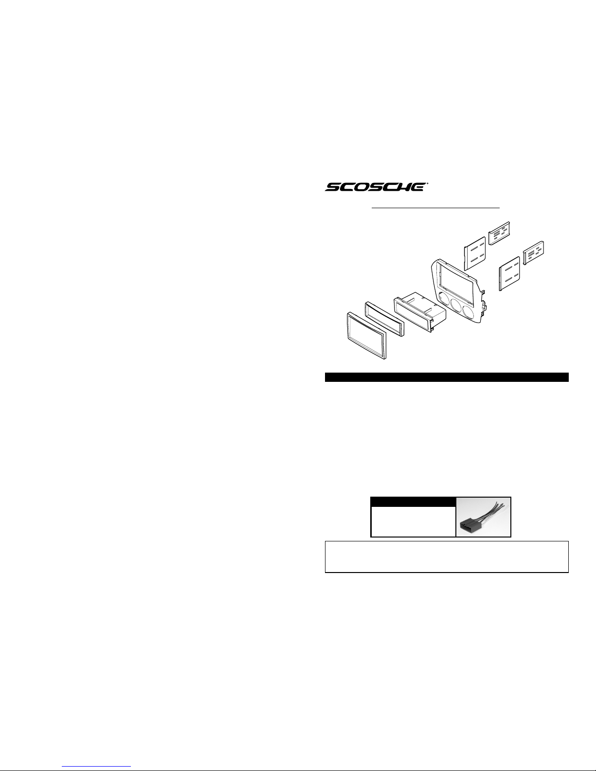
This premium installation kit is for MA1532B 2006-Up Mazda Miata / MX5 vehicles. Included are all
the parts you need to mount your car stereo/cassette or CD player into your vehicle's dash. Refer to
the individual instruction in this manual to remove your vehicle's factory radio and assemble the kit.
CAUTION:
DISCONNECT YOUR VEHICLE'S NEGATIVE BATTERY TERMINAL BEFORE THE INSTALLATION TO HELP
PREVENT ELECTRICAL DAMAGE. WE RECOMMEND THE USE OF A VOLT/OHM METER OVER A TEST LIGHT
TO CHECK WIRING. A TEST LIGHT OR GROUNDED WIRE PROBE CAN CAUSE DAMAGE TO THE VEHICLE'S
COMPUTER AND/OR DIAGNOSTIC SYSTEMS. AVOID ALL FACTORY AIRBAG WIRING - AIRBAGS CAN
ACCIDENTALLY DEPLOY CAUSING SERIOUS INJURY OR DEATH.
NOTES:
• See your vehicle's instructions for any special tools your installation might require.
• Read all instructions accompanying your car stereo/cassette player for proper wiring and mounting
instructions.
MA03B
2000-Up Select Mazda
MA03B
5742R
BRACKET
5742L
BRACKET
6248
POCKET
6228
KIT PANEL
6247 DIN
TRIM RING
5908
DOUBLE DIN
ISO BRACKET
6246
DOUBLE DIN
TRIM RING
5908
DOUBLE DIN
ISO BRACKET
4
Page 2
2
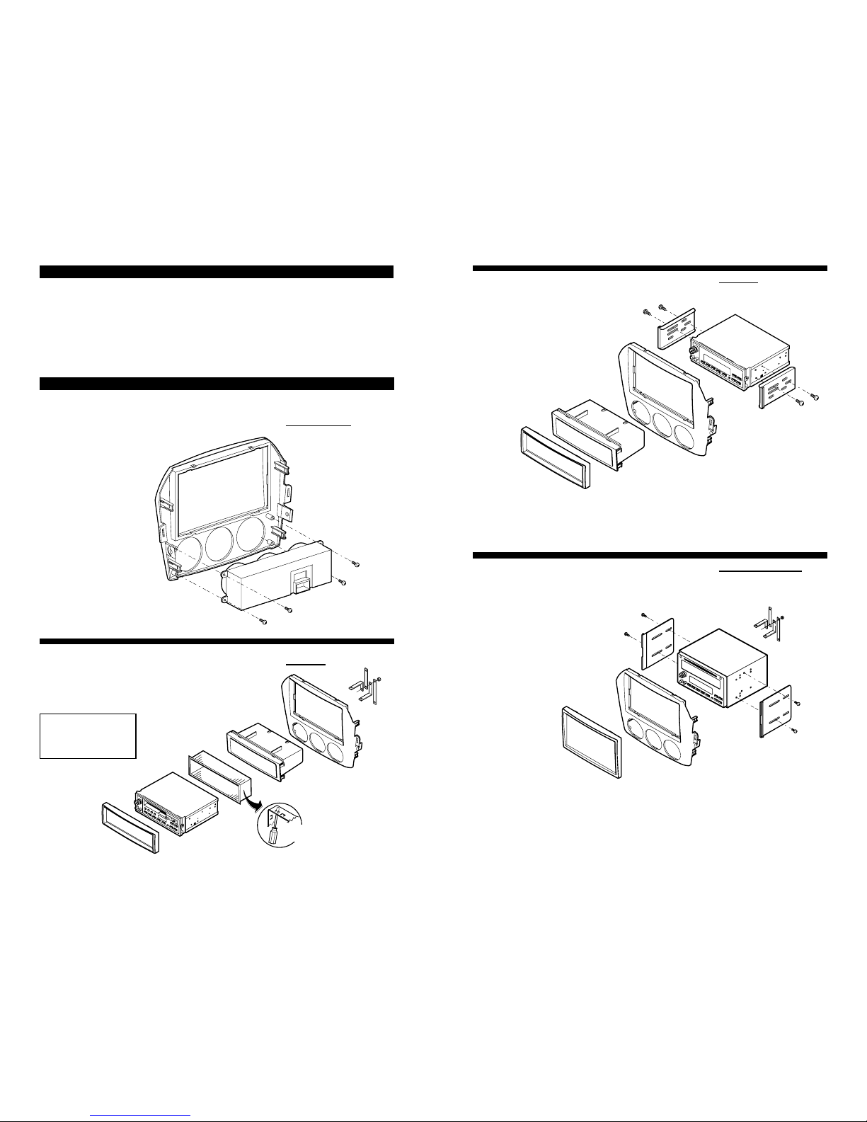
VEHICLE DISASSEMBLY
2006-Up Mazda Miata / MX5
RADIO REMOVAL:
1. Remove plastic knee guard panel.
2. Extract bolts securing knee guard panel.
3. Extract 1 hidden Phillips Head Screw securing side of radio.
4. Unsnap lower side trim panel on each side of the radio by pulling back on them and unsnap them.
5. Extract 1 Phillips Head Screw securing factory radio on each side.
6. Using a Panel Removal Tool, unsnap the parameter of the radio. Lift away disconnect and remove.
MOUNTING THE RADIO
DIN MOUNT
1. Slide pocket into kit panel from front until it snaps into place.
2. Next, slide DIN sleeve into kit panel from front and bend tabs
to hold into place.
3. Insert radio into sleeve until it snaps into place.
DIN RADIO
DIN MOUNT
REAR
SUPPORT
STRAPS
6228
KIT PANEL
6248
POCKET
RADIO
MOUNTING
SLEEVE
6247 DIN
TRIM RING
BEND TABS
OUTWARD
NOTE:
REAR SUPPORT AVAILABLE
SEPARATELY. REAR
SUPPORTING THE RADIO
ADDS TO THE INSTALLATION’S
STRUCTURAL INTEGRITY.
ISO MOUNT
1. Slide pocket into kit panel from front until it
snaps into place.
2. Slide left and right brackets into their
corresponding slots in kit panel.
3. Mount radio to brackets with radio supplied
screws.
4. Snap trim ring into
place.
DOUBLE DIN MOUNT
1. Slide left and right double DIN brackets into
their corresponding slots in kit panel.
2. Mount radio to brackets with radio supplied
screws.
3. Snap trim ring into place.
DOUBLE DIN ISO MOUNT
ISO MOUNT
6247
DIN
TRIM
RING
6248
POCKET
6228
KIT PANEL
5742R
BRACKET
5742L
BRACKET
DIN RADIO
6246
DOUBLE DIN
TRIM RING
5908
DOUBLE DIN
ISO BRACKET
5908
DOUBLE DIN
ISO BRACKET
6288
KIT PANEL
REAR
SUPPORT
STRAPS
DOUBLE DIN RADIO
3
MOUNTING A/C CONTROLS
1. Retain factory A/C controls and factory screws to be mounted onto panel.
2. Align A/C control unit and insert into panel. (Use factory screws)
3. Using factory screws, attach A/C unit to panel.
A/C CONTROL UNIT
6288
KIT PANEL
FACTORY A/C
CONTROL UNIT
*
*
*
*
USE FACTORY SCREWS
*
Choose Scosche products if you’re looking for a quality sound.
 Loading...