

Page 1
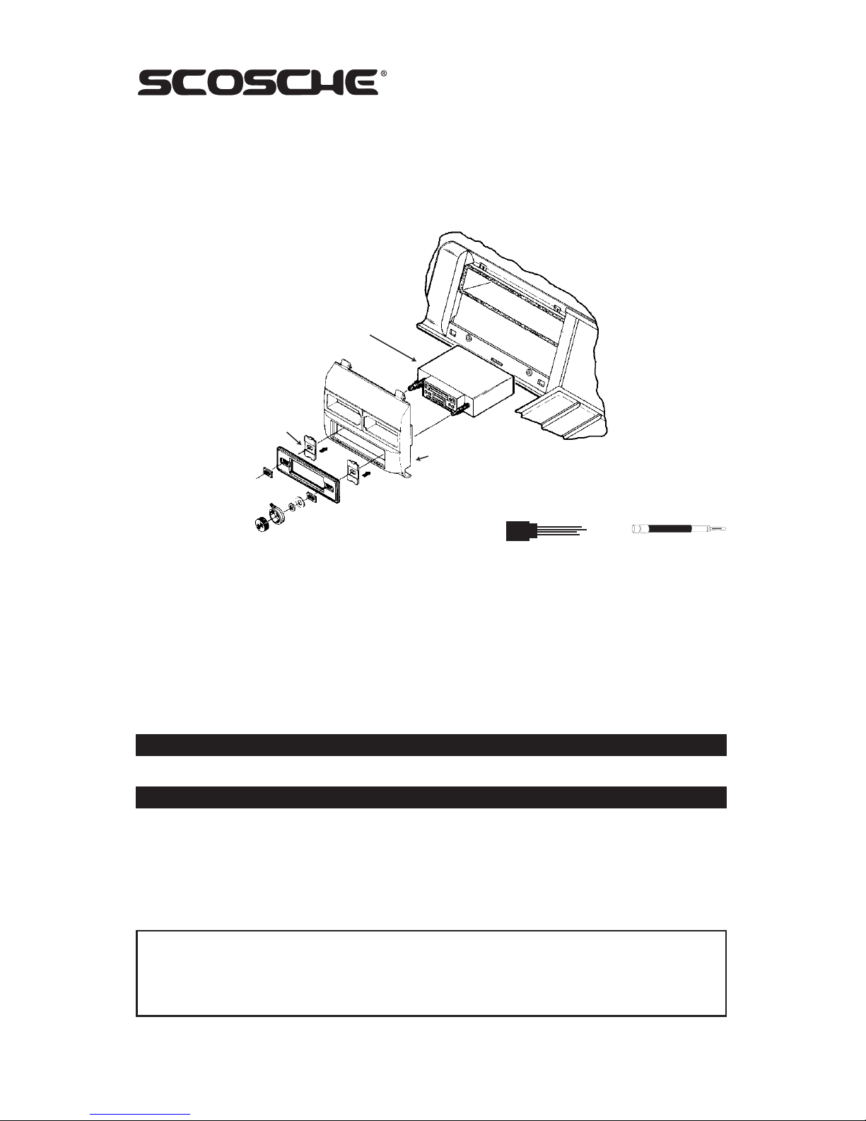
SHAFT
RADIO
SNAP
SHAFT
TABS
MOUNTING
PANEL
IN-DASH INSTALLATION KIT FOR
1988-94 GENERAL MOTORS
1500 SERIES FULL SIZE TRUCKS
TECH HELP 1-800-621-3695x3
SI 6/03 - GM1482 (3000156)
© 2003 SCOSCHE INDUSTRIES, INC.
LIABILITY DISCLAIMER
This instruction booklet is based on carefully documented data and research of automobile dash disassembly, wire harness/
codes and information pertaining to installation of this kit (GM1482) in 1988-94 GM Vehicles. Scosche Industries, Inc. can not
be held responsible for discrepancies/inconsistencies that may occur due to the automobile manufacturing changes or
options, or damage that may occur in the automobile during the installation of components while using this booklet.
Vehicle Applications:
CHEVROLET / GMC
1992-94 BLAZER - FULL SIZE
1992-94 CREW CAB DOOLEY PICKUP
1988-94 PICKUP - FULL SIZE
1992-94 SUBURBAN
1992-94 YUKON
GM1482
If you have any further questions, call
NOTE: Scosche MDA-1 antenna adapter
and GM02 factory connector (sold
separately) are needed to
complete the installation.
ILLUSTRATION A
CAUTION:
Disconnect your vehicle's negative battery terminal before the installation to help prevent electrical
Damage. We recommend the use of a volt/ohm meter over a test light to check wiring. A test light or
grounded wire probe can cause damage to the vehicle's computer and/or diagnostic systems. Avoid all
factory air bag wiring - air bags can accidentally deploy causing serious injury or death.
NOTES:
See your vehicle's instructions for any special tools your installation might require. Read all instructions
accompanying your car stereo/cassette player for proper wiring and mounting instructions.
INTRODUCTION/PRELIMINARYINTRODUCTION/PRELIMINARY
INTRODUCTION/PRELIMINARYINTRODUCTION/PRELIMINARY
INTRODUCTION/PRELIMINARY
FACTORY WIRE CODES
For Factory Wiring Codes go to: www.scosche-cars.com
Page 2
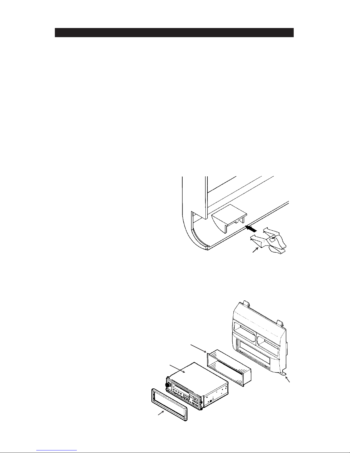
MOUNTING
SLEEVE
DIN
RADIO
RADIO'S
SUPPLIED
TRIMPLATE
MOUNTING
PANEL
TAPE PLAYER/EQUALIZER REMOVAL
AND CAVITY PREPARATION:
1. Carefully remove the factory bezel by prying out along the bottom to release fastening clips. Then
carefully pull down on the bezel to release the fasteners securing the top and remove the bezel.
2. Extract the two (2) screws securing the factory tape player/equalizer (when equipped).
3. Remove the dash panel under the steering column by extracting the two (2) screws securing it to
the dash.
4. Locate and remove the radio tuner pack under the dash above the acceleator pedal by extracting
the three (3) screws securing it to the dash.
5. Unplug all the connectors going into the radio tuner pack and remove it from the vehicle.
6. Pull the tape player/equalizer from the dash, carefully pull the plug harness through the dash from
the radio tuner pack location and remove the tape player/equalizer from the dash.
7. Locate the antenna plug and the three plugs that were connected to the top of the radio tuner pack.
Route them into the tape player/equalizer cavity. These are the factory power, speaker and antenna
plugs that will be used for the aftermarket radio hook-ups.
DIRECTIONS
ILLUSTRATION C
REAR
VIEW
OF KIT
ILLUSTRATION B
METAL
FASTENING
CLIP
GM1482 KIT PREPARATION:
1. Remove the metal fastening clips from the
bottom of the factory dash bezel and attach
them to the same location on the GM1482
kit. (See Illustration B)
2. Remove the A/C vents from the factory dash
bezel by releasing the spring fastening clips
securing them into the bezel.
3. Mount the vents into the kit by inserting the
inner edge of the vent into the center
alignment slot then insert the outer edge of
the vent into the outer alignment slot. Using
the same spring clips and mounting
procedures that were used to mount the
vents to the factory dash bezel, mount the
vents to the kit.
STEREO INSTALLATION:
1. Install the GM1482 kit into the dash by
inserting the top mounting clips into the slots
in the dash and pushing up to snap them in.
Then press the bottom clips into the slots at
the bottom of the dash to secure the kit to the
dash.
2. Connect the stereo to the factory plugs
(see Wire Codes) as directed in the
stereo installation manual.
3. Mount the stereo into the GM1482 kit as
shown in Illustration C for DIN or
llustration A for shaft.
 Loading...