

FD1360 KIT PREPARATION
IN-DASH INSTALLATION KIT FOR
1997-UP FORD ESCORT
1997-UP MERCURY TRACER
WIRING CONNECTION
CLIMATE CONTROL KNOB and HOUSING REMOVAL:
1. Carefully pull off three rotary control knobs from the
face of the factory radio/control panel.
2. From the back side of the factory control panel,
extract (1) T-20 Torx screw from the fan speed switch
housing, and twist out to remove.
3. Carefully unsnap and release temperature cable /
gear assembly from the back of the panel. Extract (1)
T-20 screw from temperature switch housing, and
twist out to remove. Be sure to leave this knob
locked in full cold position for disassembly,
reattaching it to the FD1360 panel, and reconnecting
the cable/gear assembly in the dash.
4. From the back side of the factory control panel,
loosen (4) T-10 Torx screws holding the front plastic
panel and rear metal panel together. Carefully
separate the plastic and metal panels about 1/4” to 1/
2” near the vent control housing. Use a small screwdriver to release the vent control housing clips.
5. Reattach all switches to the back side of the of the Scosche FD1360 installation panel in the
identical positions, reversing the procedures in steps #2, and #3 above.
6. Reattach rotary control knobs at the front of the Scosche FD1360 Panel.
MOUNTING CLIPS:
1. Extract (2) T-10 Torx screws holding each factory mounting clip and reattach them to the side
brackets of the Scosche FD1360 Panel.
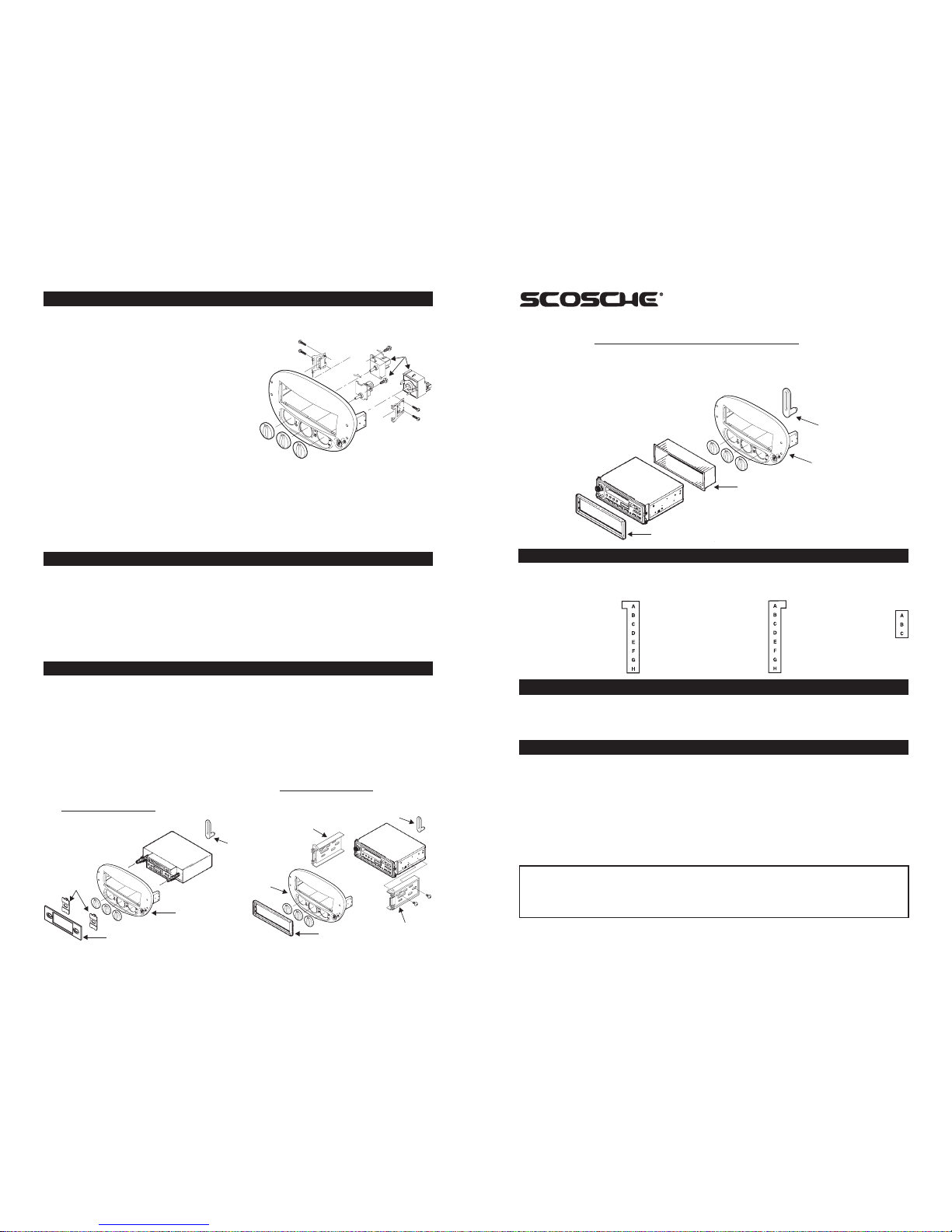
1. See illustration "A" of kit assembly for DIN radios using a mounting sleeve.
2. See illustration "B" of kit assembly for Shaft Radios.
3. See illustration "C" of kit assembly DIN ISO (REAR LOAD) radios. DIN ISO mount requires left and
right bracket assemblies to be snapped into the installation panel. Secure the radio chassis with the
short metric hardware supplied with a DIN ISO radio. Snap in DIN ISO trim ring around nose-piece of
radio. See illustration "C".
WARNING: DO NOT USE SELF TAPPING (DRYWALL) SCREWS OR SCREWS LONGER THAN
6MM (1/4") FOR DIN ISO MOUNT. DAMAGE MAY RESULT IF SCREWS WERE TO PIERCE
INTERNAL CIRCUITRY OF RADIO.
4. Scosche recommends rear support on all installations. Attach rear support piece to rear of stereo
and adjust as necessary. See Illustration "A", "B", or "C".
ILLUSTRATION "C"
STEREO INSTALLATION
FD1360
MOUNTING
PANEL
ILLUSTRATION "A"
DIN MOUNT INSTALLATION
(Front Load)
REAR SUPPORT
FACTORY WIRING CODES
INTRODUCTION
Thank you for purchasing the Scosche FD1360 installation panel. The FD1360 replaces the Factory
Integrated Radio / Climate control panel, while using original Rotary Climate Knobs and Housings. The
FD1360 Allows the proper installation of Aftermarket DIN, Shaft, and DIN ISO types of Radios, while
maintaining the original Factory styling, fit, and function.
NOTE: • All wire codes are viewed as looking at the front of the plug with the wires exiting the rear.
• Use these wiring codes as a guide. Your vehicle might differ.
Gray Connector - Power:
A = +12V Constant, Battery
B = Dimmer
C = +12V with Ignition
D = Panel Light
E = Empty
F = Ground
G = Empty
H = Power Antenna
Defroster Connector:
A = Ground
B = +12V when on
C = Defroster Trigger
(Negative)
Black Connector - Speaker:
A = Left Front Positive
B = Left Front Negative
C = Left Rear Positive
D = Left Rear Negative
E = Right Front Positive
F = Right Front Negative
G = Right Rear Positive
H = Right Rear Negative
1997-UP FORD ESCORT/MERCURY TRACER
FACTORY STEREO REMOVAL
ISO MOUNT
BRACKET
DIN RADIO
FACE PLATE
SHAFT
RADIO
SHAFT RADIO FACE PLATE
REAR
SUPPORT
SNAP
SHAFT
TABS
FD1360
MOUNTING
PANE L
ILLUSTRATION "B"
REAR SUPPORT
DIN ISO
RADIO
FD1360
MOUNTING
PANEL
ISO MOUNT
BRACKET
CLIMATE
CONTROL
HOUSINGS
DIN RADIO FACE PLATE
DIN RADIO
RADIO MOUNT
SLEEVE
NOTE: The wire colors of your radio may differ from those on the Scosche Connectors. Consult your
Stereo owner’s manual to match the wire functions correctly. Terminate all unused wires properly.
1. Connect the power wires of your radio to the gray power connector and the speaker wires to the
black speaker connector of the Scosche FD17 Escort harness.
2. Connect the black and orange wires from the back side of the FD1360 installation panel to the black
and Orange wires on the gray power connector. Extra black and orange leads are provided on the
gray power connector.
3. Connect the small red and black wires from the back of the FD1360 installation panel to the red and
black wires on rear defroster plug.
1. Rotate temp control to full cold (counter clockwise).
2. From driver’s (left) side underdash, remove temperature control cable from heater box by releasing
tab, then pulling straight off.
3. Using Scosche DT-1 DIN removal tools carefully insert them into the holes on the outside edges of
the radio/control panel to release, unplug all connectors, vacuum lines, and pull the factory radio/
control panel out of the dash.
4. Unplug all wiring connectors, antenna and unsnap temperature control cable from back panel of
factory control panel.
5. Remove the factory radio from the dash. Pull three climate control knobs off control panel face. Then,
remove control housings from back of control panel by unscrewing (2) torx screws and twist out to
remove.
This instruction booklet is based on carefully documented data and research of automobile dash disassembly, wire harness/codes
and information pertaining to installation of this kit (#FD1360) in 1997-UP Ford Escort and Mercury Tracer Vehicles. Scosche
Industries, Inc. can not be held responsible for discrepancies/inconsistencies that may occur due to the automobile manufacturing
changes or options, or damage that may occur in the automobile during the installation of components while using this booklet.
LIABILITY DISCLAIMER
FD136010
SHAFT RADIO
INSTALLATION
DIN ISO MOUNT INSTALLATION
(Rear Load)
 Loading...