

Page 1
1. Disconnect the Negative battery cable from the battery to avoid
short circuits.
2. Remove and unplug factory stereo.
3. Match and connect the appropriate wires from the DDR-GM01
harness to the appropriate wires of the plug provided with your
aftermarket stereo. for example, connect the +12V “yellow”
constant lead from your stereo to the “yellow” wire on the
DDR-GM01 harness. The color code are designed to match most
brands of aftermarket car stereo.
4. Solder steering wheel control Input wire (green/black) to factory
steering wheel control data wire (green/black)found behind the
panel under the steering column. DO NOT CUT THROUGH WIRE.
See pg6. for details.
5. Tape all unused wires to prevent wires from short circuiting.
6. Reconnect Negative battery cable.
7. Set the DIP Switches according to instructions below.
8. Set steering wheel controls according page 3.
9. Make all connections to the DDR-GM01 including the chime
speaker, prepared steering wheel control harness, power
harness, and video RCA.(If used, plug aftermarket reverse camera
to female RCA connector.)
10. Make all connections to your aftermarket stereo including the power
andspeaker harness, video input RCA, and steering
wheel control jack or wire.
11. Make connection to our vehicles factory stereo harness.
12. As you install your new stereo, place the DDR-GM01 module in the
rear or to the side of the dash cavity out of the way of the stereo.
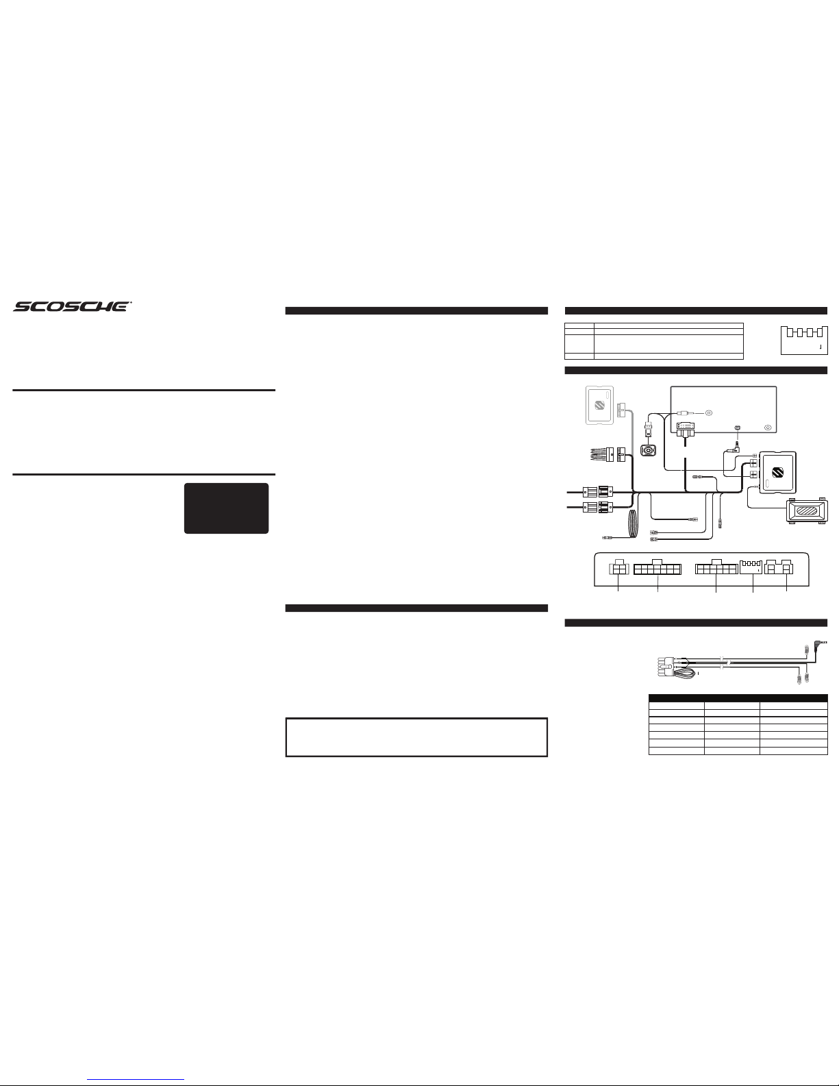
INTERFACE CONNECTIONS
Reverse Camera output
to head unit and reverse
camera input from
optional camera
Power Harness Steering Wheel
Remote control
connector to
head unit
Dip Switches
Chime
Box
1 2 3 4
DIP ON
DDR-GM01
Park Brake
(Green)
Amp Remote Out
(Blue/White)
Mute(Yellow/Black)
Speed Pulse (Pink)
Reverse (Violet/white)
Aftermarket headunit unit
DDR-GM01
Chime
Speaker
Steering Wheel
Control Jack
Aftermarket
Radio
Connector
Reverse Camera Input
Reverse
camera
(optional)
To car connector
1: SWC ON = Pioneer OFF = All other brands
2: CAMERA ON = PAL OFF = NTSC
3: RESET Turn from OFF to ON, then back to OFF. This will reset the Screen
settings back to default. Screen will change to red and back to
default to verify procedure.
4: N/A
1 2 3 4
DIP ON
DIP SWITCH SETTINGS
Up = OFF
Down = ON
gmos1
GMOSM1
OnStar
Module
(optional)
Steering Wheel
Control Input
(Green/Black)
INSTALLATION
WIRE COLOR CODES
White
White/Black
Green
Green/Black
Violet
Violet/Black
Gray
Gray Black
Green/Black
= Left Front Positive (+)
= Left Front Negative (-)
= Left Rear Positive (+)
= Left Rear Negative (-)
= Right Rear Positive (+)
= Right Rear Negative (-)
= Right Front Positive (+)
= Right Front Negative (-)
= Steering Wheel Control
Data
Black
Yellow
Red
Blue/White
Orange
Yellow/Black
Green
Pink
Violet/White
= Chassis Ground (-12V)
= +12V Battery Constant
= +12V Ignition Switched
= +12V Remote Output
(Amp Remote, Radio On Signal)
= Illumination Output
= Mute
= Park Brake
= Speed Pulse
(VSS)
= Reverse
The color codes used in this car stereo connector conform to the standards set by the E.I.A.
(Electronics Industry Association). They may differ from the wiring codes found on your specific car
stereo. Always refer to your stereo owner’s manual for wiring details about your specific car stereo.
Be sure to insulate unused wires from each other and from ground. Failure to do so can result in
damage to the stereo and/or the vehicles electrical system.
STEERING WHEEL WIRING CODES
2 3
KEY 1
KEY 2
3.5mm
GND
Purple, Green, Orange Loops
1. Prepare SWC steering wheel connector harness by using the chart below.
2. Connect the harness to the interface module.
3. For Alpine, Clarion, JVC, Panasonic and Sony car stereos, connect the 3.5mm male
steering plug into the steering
wheel input jack at the back of the
stereo.
4. For Kenwood and newer JVC
stereos, connect the BROWN wire
from the steering wheel harness
to the “Remote in” wire at the
back of the stereo.
ALIPNE
CLARION
JVC
KENWOOD
PANASONIC
PIONEER / SONY
OTHER BRANDS
Cut Green Loop
Cut Violet Loop
Cut Green & Violet Loop
Cut Ornage & Green
Cut Orange
Do Not Cut Loops
Call Tech Support
3.5mm
3.5mm
3.5mm or Brown (Key1)
Brown (Key 1)
Brown (Key 1)
3.5mm
Brown, Gray, Black
STEREO BRAND CONFIGURATION CONNECTION TO STEREO
DDR-GM01
2014-UP CHEVROLET
FULL SIZE TRUCKS
DATA & DISPLAY RETENTION INTERFACE
The Scosche DDR-GM01 allows vehicle information such as climate
control, parking sensors and heated seats to be displayed on any
aftermarket head unit with rear camera input. The DDR-GM01 will also
retain steering wheel controls. Extensive vehicle settings can also be
adjusted from the steering wheel controls.
WORKS WITH:
2014-Up Silverado
2015-Up Suburban
2015-Up Tahoe
RETAINS:
• Climate Control Visual Display
• Park Assist Visual Display
• Vehicle Settings Menu
•
•
Steering Wheel Controls
OnStar with GMOSM1
(Sold separately)
OUTPUTS:
• Data Driven +12V
Accessory
(R.A.P.)
• Illumination
• Vehicle Speed Sense
• Parking Brake
• Reverse
Requires aftermarket AV/AVN head unit with rear camera input and reverse trigger. For
use in vehicle equipped with MyLink factory navigation.
1
TO RETAIN OnStar
GMOSM1
(sold separately)
MUST BE INSTALLED
WITH THIS INTERFACE.
Page 2
Select “Infodapter Settings” menu to
access and change attributes of the
DDR-GM01 interface.
Select “Screen Size / Position” menu
to calibrate video size and position.
Use corner outline marks to ensure
after market stereo reverse camera
warnings appear outside of the
DDR-GM01 video display. Refer to
after market stereo’s manual for
instructions to remove reverse
camera guides and marks.
Logo
Preferences
Driver Position Right
Park Assist Version 0
Camera Connected Yes
Reverse Priority Park Assist
Park Brake Source Speed
Bluetooth On
Steering Wheel 7 Function
Restore factory settings
Picture Settings
Brightness
Contrast
Saturation
<Back
Infodapter Settings
Screen Size / Position
Picture Settings
Preferences
<Back
Select “Picture Settings” menu to
adjust the Brightness, Contrast,
and Saturation of the DDR-GM01
video signal.
Park Brake Source:
Select Speed, Brake, or Always
On.
Bluetooth:
Enables Pick Up / Hang Up
Steering Wheel Control
functions.
Steering Wheel:
Select correct Steering Wheel
Control button layout.
Logo:
Select for relevant Vehicle or
stereo brand logo to be
displayed on factory for line dash
display.(Does not support OEM
NAV display.)
Restore Factory Settings:
Restores all DDR-GM01 settings
to defaults.
Screen Size/Position
Horizontal Size
Horizontal Position
Vertical Size
Vertical Position
< Back
Driver Position:
Select left or right hand drive.
Park Assist Version:
Select Park Assist graphic style.
Camera Connected:
Select if you have a Reverse
Camera installed.
Reverse Priority:
Toggles between Park Assist
graphic or Reverse Camera as
default view. Press “Source”
button during reverse to toggle.
5
MENU ACCESS AND CONTROL ... Continued
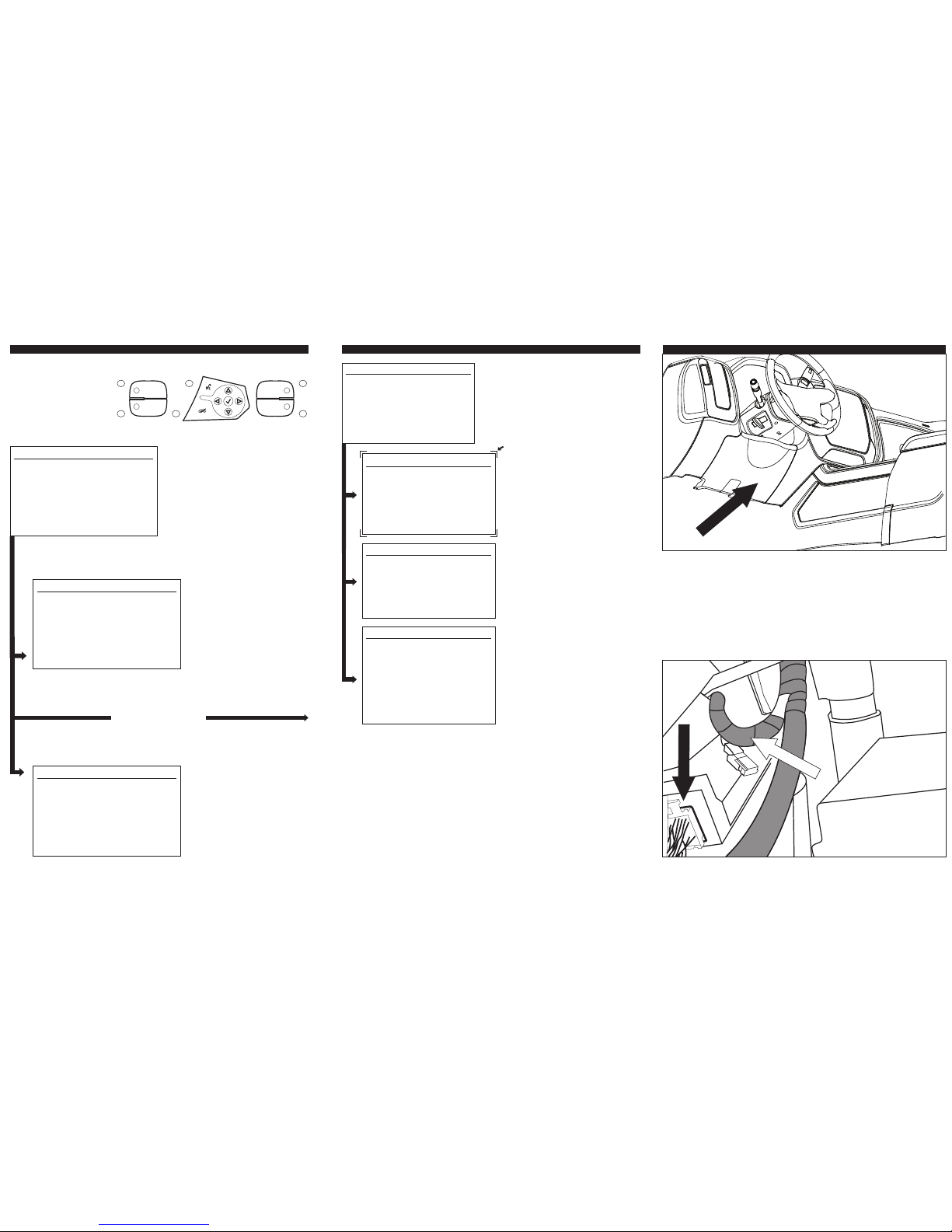
1) Remove 2 T15 screws from underside of Knee Bolster and pull to unclip.
2) Unclip hood release and set panel aside.
3) Locate cloth wrapped wire bundle joined to a nylon braid covered bundle
to right of the BCM.
4) Carefully remove a section of the cloth tape to reveal the wires
5) Locate the Green/Black wire and strip it WITHOUT cutting through it.
6) Twist, Solder and tape the Green/Black Steering Wheel Control wire from
the DDR-GM01 Harness.
7) Reattach hood release then clip and screw the Knee Bolster back in
place.
STEERING WHEEL CONTROL CONNECTION
BCM
SWC WIRE
REMOVE
6
To access the menu, push and hold
the Speech button for 2
seconds.This will enable the
configuration root menu. To navigate
through the menu options use the
Track Up / Track Down SWC
buttons. To select a menu option,
push the Speech button once.
1. Track Up (Menu-Up)
2. Track Down (Menu-Down)
3.. Answ
BT
/ Menu
hold
(Select)
4.. E
BT
/ Mute
5. Vol Up
6. Vol Down
Confi guration Menu
Vehicle Settings
Infodapter Settings
Language
Version
< Back
Vehicle Settings
Select “Vehicle Settings” menu
to access factory settings
originally accessed through
OEM stereo.(For details of
individual menu items refer to
your vehicles user manual.)
Language
English
Deutsch
Nederlands
Francais
Italiano
Select “Language” menu to
access available languages. If
set to incorrect language, the
language menu will always be
the third selection down in the
root menu.
Sport Mode Settings
Time/Date
Climate and air quality
Comfort Settings
Park assist and collision detection
Exterior ambient lighting
Power door locks
Remote locking,unlocking, starting
Polski
Infodapter Settings
LEFT SIDE RIGHT SIDE
1
2
5
6
3
4
4
Fig 2.
MENU ACCESS AND CONTROLMENU ACCESS AND CONTROL
Steering Wheel Control Legend
On our website you can discover more about car stereo and video installation parts.
 Loading...