

Page 1
HANDS-FREE BLUETOOTH INTERFACE FOR
SELECT 2006-UP ACURA/HONDA VEHICLES
APPLICATION GUIDE
ACURA
2006-09 MDX
2006-09 RDX
2006-09 RL
2006-08 TSX
2006-08 TL
HONDA
2006-09 ACCORD
2006-09 CIVIC
2006-09 CRV
2006-09 ELEMENT
2006-09 FIT
2006-09 ODYSSEY
2006-09 PILOT
2006-09 RIDGELINE
2006-09 S2000
BFHA
QUICK START
INSTALL
Using the BFHAHB harness, install the BFHA interface into your vehicle.
Contact Scosche Tech Support for your specific vehicle disassembly.
POWER THE MODULE
With the unit installed, turn the ignition key to the on position to place the
Bluefusion module into pairing mode. Press your radios designated XM
button to enter the XM (Bluefusion) source. From the XM source press the
preset number 6 button, the screen displays “Bluefusion” when ready.
PAIR YOUR CELLULAR PHONE
Set your cellular phone into pairing mode and search for a new Bluetooth
device (See your phone’s owners manual for instructions). Once your
cellular phone has searched for a new device, select “BLUEFUSION” from
the list of devices found. If prompted for a pass code enter “0000”.
4
Once the two devices have connected and paired, you will be able to scroll
through the menu functions of the BFHA. (See page 2-4 for Bluefusion
operation).
NAVIGATE AND ENJOY
©2009 SCOSCHE INDUSTRIES, INC.
SI 06/09 BFHA (3000000)
Page 2

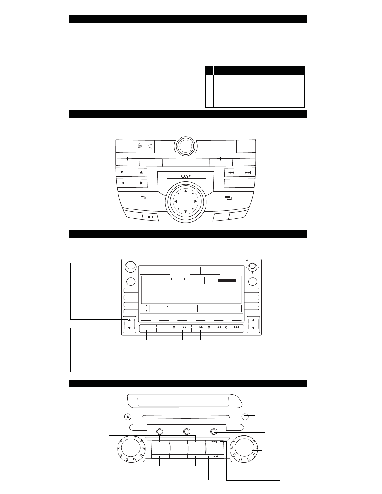
INSTALLATION OVERVIEW
24-Pin
RADIO
HARNESS
3-PIN
MICROPHONE
HARNESS
PAIRING YOUR MOBILE PHONE
1. Turn the key to the on position (II) to place Bluefusion into pairing mode.
2. Press the appropriate button to get to your XM source, then press and hold
the preset number 6 to enter Bluefusion, screen displays “BLUEFUSION”.
3. On your cellular phone, enter your Bluetooth menu and make your cellular
phone search for a new bluetooth device. The device name will be
“BLUEFUSION” and if you are prompted for a pass code enter “0000”.
4. When the two devices are paired to each other, be sure to set the Bluefusion
as a trusted device on your cellular phone.
NOTE: When the ignition is turned off the call
will automatically transfer to the headset.
NOTE: When a phone call is active and you
are re-entering the vehicle, the call will not
automatically transfer to Bluefusion. Active
calls will remain on the cell phone untill the
next active phone call.
These notes are assuming the cellular
phone’s bluetooth feature is set to “ON”.
SWITCHING RADIO SOURCES
While using other sources other than XM (Bluefusion) the interface will automatically switch to the XM source when you have an incoming phone call. The radio
switches through the sources to find the XM source on the radio, some audio
may bleed through while switching sources.
When a phone call is ended your radio will not automatically switch back to the
original source you were previously on, this feature only works when previously
on XM source. At this time we recommend switching back to the original source
you were previously on.
Page 3
RADIO OPERATION
RADIO CONTROLS MAY VARY.
There are different buttons used for each of the individual radios.
Please read and understand this entire manual before operating the interface.
THIS CHART IS TO BE USED FOR
ALL RADIO STYLES BELOW.
PRESSET NUMBERS FUNCTION
THE SAME FOR RADIOS LISTED
BELOW.
RADIO STYLE #1
ENTER XM/
BLUEFUSION
VOL
PUSH
PWR
3456
MAP GUIDE
SCROLL UP/
TITLE
CATEGORY
1
TUNE
XM
FM/AM
2
SCROLL DOWN
ENTER
AUDIO
RADIO STYLE #2
P = PRESET NUMBER
P FUNCTION
1 SELECT/ ANSWER
2 ACTIVATE VOICE DIAL
4 END/ CANCEL/ IGNORE
6 TOGGLE XM/ BLUEFUSION
PRESETS 1-6:
SEE PRESET
SOUND
INFO
AUX
CD
SKIP
SCAN
A.SEL
MENUCANCEL
SETUP
CHART FOR
PRESET
FUNCTIONS
SKIP FWRD:
SELECT/
ANSWER
SKIP BACK:
CANCEL/ END/
IGNORE
PRESS:
SCROLL UP/
ANSWER
PRESS & HOLD:
SELECT/
ANSWER 2ND
INCOMING CALL
PRESS:
SCROLL DOWN/
END/ IGNORE
PRESS & HOLD:
CANCEL
PRESETS 1-6:
SEE PRESET
CHART ABOVE
FOR PRESET
FUNCTIONS
ENTER XM/
BLUEFUSION
ANTI
VOL
PUSH
PWR
AMFM1 FM2 XM1 XM2 CD CARD
OPEN DISP
AM/FM
CD/AUX
AUDIO
SCAN
TUNE
FOLDER
333 VOL 7
CHANNEL
CATERGORY
NAME
TITLE
CH +
TUNE
CH -
1
1RPT
022-Missed
Missed
Missed
Missed
CATEGORY +
CATEGORY -
2RDM
45
3
MODE
Sound Backround
33 5420
24
5
4
THEFT
CHANNEL
6
RADIO STYLE #3
DISP
AM FM CD/AUX
123
DISC
DISC
456
RPT
+
-
RDM
SEEK/SKIP
A.SEL
TUNE
FOLDER
PUSH
SOUND
VOL
PUSH
PWR
SCAN
SHOW TITLE
MAP
MENU
SET UP
CANCEL
IN
ZOOM
OUT
PRESETS 1-6:
SEE PRESET
CHART ABOVE
FOR PRESET
FUNCTIONS
SHOW TITLE
ENTER XM/
BLUEFUSION
SCROLL UP/
SCROLL DOWN
CANCEL/ END/ IGNORE
SELECT/ ANSWER
Page 4

TRANSMITTING MUSIC USING BLUETOOTH
IN ORDER FOR THIS FUNCTION TO WORK A CELLULAR
PHONE MUST BE PAIRED AND CONNECTED
When listening to audio from a stereo Bluetooth receiver the audio will be
interrupted (not paused) when a phone call comes in.
Controlling your stereo Bluetooth transmitter via AVRCP:
Play/ Pause – Not functional through the radio control.
(Use the controls on your external device).
Track Forward – Press the Seek Forward button.
Track Back – Press the Seek Back button.
USING THE STEERING WHEEL CONTROLS
USE THE CHART BELOW FOR SW#1 ONLY. (SEE ILLO BELOW FOR SW#2)
ANSWER/2ND CALL
END/IGNORE
TRACK FOWARD
TRACK BACK
SW#1(USE CHART ABOVE) SW#2(USE ILLO BELOW)
ANSWER/ 2ND CALL/
CH
END/ IGNORE
PRESS THE CHANNEL BUTTON. (SEE ILLO BELOW FOR SW#2)
PRESS AND HOLD THE CHANNEL BUTTON. (SEE ILLO BELOW FOR SW#2)
PRESS THE CHANNEL BUTTON. (SEE ILLO BELOW FOR SW#2)
PRESS AND HOLD THE CHANNEL BUTTON. (SEE ILLO BELOW FOR SW#2)
ANSWER/ TRACK FWD
VOL
CH
+
VOL
MODE
TRANSFER TO
HEADSET
-
MODE
TRANSFER TO
HEADSET
The MODE button will always route your conversation back to the cellular phone,
also known as privacy mode (ex. when exiting the vehicle).
TROUBLE SHOOTING
NO AVRCP CONTROL
RANGE ISSUE
DEVICE NOT FOUND
BAD CALL QUALITY
NO SOUND
AUDIO DROP OUTS
Verify that the paired device supports AVRCP functionality.
Bluetooth standard range maxing out at 30 feet, may vary
due to environment.
Delete all previous pairing attempts and try again.
Make sure the cellular is within range of the module (30ft.).
Make sure the signal reception of the cellular phone is strong.
Make sure the module is on and paired to transmitting device.
Make sure the volume is correct, check both the radio and
the transmitting device, and other items within range.
Make sure the transmitting device is at a good battery state.
If the item in on low battery, please recharge.
NOTE: Due to every phone having different software and functionality features,
many phones may work different with the Bluetooth module of the BFHA. We
recommend contacting the Scosche Technical Support at 1-800-621-3695 Ex.3
with any common or reoccurring issues.
END/ IGNORE/ TRACK BACK
Scosche Industries Inc. warrants this product to be free from defects in material and workmanship for a period of 90 days
from purchase. This Scosche product is sold with the understanding that the purchaser has independently determined the
suitability of this product. This warranty is offered to the original purchaser of the product only. This warranty does not
cover the product if physically damaged, subject to negligence or misuse, abuse, alteration, accident, or an act of GOD.
This warranty does not apply to product which has water or physically damaged by accident or which has been misused,
disassembled or altered.
The original dated sales slip or proof of purchase will establish warranty eligibility. If the product should prove defective
within the warranty period, return the product with proof of purchase to Scosche Industries Inc. Scosche, at its option, will
replace or repair the product free of charge and return the product postage paid. In no event shall Scosche Industries, Inc.
be responsible for claims beyond the replacement value of the defective product, or in any way be liable or responsible
for consequential or incidental damages. No express warranties and no implied warranties, whether for fi tness or any
particular use or otherwise, except as set forth above (which is made expressly in lieu of all other warranties) shall apply
to products sold by Scosche. Scosche Industries cannot be held responsible for discrepancies/inconsistencies that may
occur due to automotive manufacturing changes or option.
LIMITED WARRANTY
Page 5

INSTAL.LATION
BFHA
INTERFACE
INSTALLATION
1.
Remove
radIo
2.
Insert
Scosche"T"
harness
Into
radio
and
faCtory
harness
3.
locate Steering
Wheel
Controlinformation
from
the
list
on
reverse.
page
4.
Use
supplied
T-Tap
to tap
SWC
wire
then connect to appropriate
T-harness
SWC
wire.
S.
If
SWC
wire
Is
not present,Insertsupplied terminated cable into the the
SWC
wire's
loc;atlon
then
c~mnect
to appropriat¢
T..,harness
SWC
wire.
6.Plug
24pin
p.lug
irito
Bluefuslon
Interface.
.
.tech
Tip:
When
mou~tlng
the
BFHA
m;ke sure to be
clear
ora
II
moving
mechanical
d~vice
that
may
hit ordamagethe
Interface.
Keep
away
from'
any
hot surface
'areas
like
heater ducts direct
sun
light
and
metal surface
areas,
that
have
the potential
of
getting hot.
FACTORY
HARNESS·
1.,.
1].
l-
~.
•
I·NSTA~LATION
OVERVIEW
MICROPHONE
o
24-Pin . •
1
~.""'''''g:]3=J.1
BFHA
MICFlOPHONE
INSTALLATION
1.
Attach
the microphone
on
the headliner above the
rear
view
mirror.
2:
Routt:
the microphone
cabfe
through the headliner and
"A"
pillar
to the interface location.
3.
Plug
In
the
3-pln
molE~x
connectorto the
pigtail
on
th~
Socshe
NT
harness,
,
.
.FACTO,RY.
:
RADIO
IMP
0
RTA
NT
~~~~~li~lI\I\M"
111!''',11
~I\HJ11I1I1V
llllM
~pr\IIP~11
IF
YOU
NEED
I\SSISTI\NCE
OR
HEPLI\CEMENT
PI\R1S
CI\I\
115!OII
IIHr
.
1-!l{)O·621·3h'J~
X.3
,
REV.l
_
..
--'
--"
..
_
..
-'_
..
-'-'--"-"--'
-:-------_.
**C
GREEN
,
B
ORANGE
Cl..
a
-
**L1FT
BLACK
RETAINER
CLIP
BEFORE
INSERTING
PIN
A
BROWN
Cl.
a
-
NOTE:
WIRE
COLORS
MAY
VARY
FROM
THOSE
LISTED
.\
CONNEaOR
0 '
!'
PINS
'CONNEaORC
PINe
, r .
f
.'
:."
I
ALLVIEWS
~RE
FROM
WIRE
SIDE
~F
CONNEGTOf
'1~1111~llljl~l:
I I
1191
=uIT1
11'1
II
~2
• ' •..
,'
ORN
f
..
t: ;
'i
CONNECTOR
A
PIN
A
CONNECTORB
PINS
11~1
~.
20
GRN/RED
WHT
PNK
ORN
YEL
I~'·~I
1
I I I
~6111
~
.>4
PNK
Page 6

SWC
1) Determine from
connector
which
INSTALLATION'
drawingtoreference.
In
this caseweareinan
is listed as connector
the
list which
09Accord
PROCESS
8.
2)
And
the
locationshown
(aswritten in
arefrom wire side
views
As
shown,
pin 16.
SteeringWneel
In
the
connectordrawing
the
connectordrawing;all
SWC
wire
in
Control
of
connectorB
'pin
connector)
is
-
IoIlOWH
a
NOTE:
A
ACURA
.
3)
4) If
MOX
RL·
W1RE·COL.O~
FROMTHOSEUSTED
If
this pin locationisalready
connecttothe
marked "Pilot
the
drawing
In
this
~
MAY
SWC
pin
Iccation
to
determine
casewe<!re,
•
a
-
.C
A
VARY
populated
brown'wire marked
in
caseofthe
IS
NOT
populated
whichofthe
g'o;ngtouse pin Bwith
**C
GllEEN
simplyT-tap'and'
IISWC
(purple wire
Pilot)
and
skiptostep
then
reference
supplied pinned wirestouse.
the
orange
7.
the
c:onm:!ctor
wire.
AU.
VIEWS
ARE
FROM
WIR"E'SJOEOF
5) l,ift
the
retainerclip'
and
Insert
the
the
pin locatioh determined instep 2
(note
the
orientationtothe
clip listed in
6)
Connect
(which
connector)tothe
·SWC"
in
caseofthe
the
the
is
now inserted
(purplewire marked "Pilot
on
supplied pinned wire into
pin drawing}.
supplied pinned wire
brown wire marked
Pilot).
CONNECTOR
the
'corinector
connectors
intO
the
SWCIt
-UFT
BLACK
RETAINER
BEFORE
INSERTING
....
-.
iMPORTANT
IF
YOU
NEED
REPLACEME.NT
ASSIS
CLIP
PIN
rANCE
PARTS
OR
~'~~~1~18AM~JO(PSll
SATli/IOIIY
CALLUSTOLL
1·800·621·369~
7)
YO'u
are now readytopl(J9.inthe
T-Harness assembly
BlueFusion interface module.
8)To
test,
start
StartGuide
phoneispaired,switch radio to
source
radio switchessourcestoBtueFusion
all
connections
8IIM·]I'o\I1
(PST
I
fREE
X3
to
and
makeanoutgoing
REV.
vehicle
pairyour
are correct.
1
and
and
phone.
the
follow Quick
Once
FM
call.
If
Page 7

BFHA
QUICK
STEP1-PAIR
1.
Turnonyour
2.
Select
"Blue
STEP2-ACCESSING
1.
Press
the
modeofyour
2.
Now
push
3.
"Blue
Fusion"
STEP3-HANDLING
1.
To
mmDll
YOUR
vehicle
Fusion"
PHONE
and
enable
and
Enter
81ueFusion
Em
or
om
stereo.
~
willbedisplayedonradio
CALLS-
a
call
press
the
Bluetoothonyour
Passcode:
0000
buttontoaccess
(if
youdonot
have
screenordisplay.
ANSWER,
START
cell
phone.
the
~
SAT
RADIOorSATTUNER
END,
IGNORE
buttononyour
installed,
steering
skip
this
wheel
step)
or
2.
3.
stereo
To
mIl]
Button
To
ImlD
to
the
use
ringing.IfIgnore
81ueFusion
MISSED
IMCOMING
OUTGOING
REDIAL:
VOICE
DIAL:
MENUS
CALLS:
CALLS:
CALLS:
Redials
BlueFusion
mmDll
call,
press
mDiD
an
incoming
call
BlueFusion
Easily
access
Easily
access
the
last
number
will
the
call.Ifanswering
the
~
phone
call,
press
fromaStereo
keepsalogofunanswered
phone
outgoing
dialed.
trigger
the
voice
Button
numbers
numbers
fromaStereo
the
use
from
dialed
dial
functionofyour
button.Ifending
~
mDiD
and
ignored
calls
you
received.
from
your
phone
•
Button
use
fromaStereo
calls.
phone.
.
Tech
Support:
800.621.3695
mlI:mD
button
while
ext.3
*For
more
detailed
instructions,
consult
your
BlueFusion
owner's
manual.**Some
features
may
vary
dependingonyour
cellular
phone
model.
Page 8

BFHA
8)
Bluetooth®
STREAMING
MUSIC
TOAFACTORY
Scoscheispleasedtobring
handsfree
integrates
music
HAN
device
DSFREE
Bluetooth®
your
Bluetooth®
into
the
CELLU
factory
LAR
HANDSFREE
you
BlueFusion,
car
kit.
BlueFusion
enabled
audio
cellphoneorstreaming
systemofyour
STREAMING
CELLULAR
HONDA
STEREO
the
ultimate
seamlessly
vehicle.
m
MUSIC
AND
BlueFusion
mute
your
asacall
the
answer/hangupon
will
automatically
musicinany
comes
in,
radioorsteering
answer
fidelity
cancellation
crystal
www.~~~~c::I-IG.com
the
microphone
advanced
software
clear
conversation
in
noisy
The
Bluetooth
word
call.
DSP
vehicles.
©2010
mark
simply
wheel
The
noise
ensures
SCOSCHE
and
logos
are
source
press
the
to
high
and
a
even
INDUSTRIES,INC.
ownedbythe
Bluetooth
streaming
A2DP
can
from
Scosche
Bluetooth®
Oxnard,CA93033
SIG,
Inc.&any
useofsuch
BlueFusion
supports
music
enabled
also
stream
your
cell
music
iPod
phones.
tuneSTREAMTM
transmitter.
(sold
5000478
separately)
Tech
Support:
•
marksbyScoscheisunder
800.621.3695
3/10
with
with
license.
most
You
directly
the
stereo
ext.3
 Loading...