

Page 1
IRD-2900 Series
Professional Integrated Receiver Decoders
U
SER
M
ANUAL
S
COPUS DOCUMENTS (P/N
100793)
(REV. 4.6/ SW V1.80/ D
ECEMBER
2007)
Page 2

Page 3

IRD-2900 Series
Professional Integrated Receiver Decoders
IRD-2900 Series
Professional
Integrated Receiver Decoders
U
SER
M
ANUAL
S
COPUS DOCUMENTS (P/N
100793)
(REV. 4.6/ SW V1.80/ D
ECEMBER
2007)
Page 4

Page 5

Scopus Video Networks Ltd.
International Headquarters
Scopus Video Networks Inc.
America
10 Ha’amal St., Park Afek
Rosh Ha’ayin, 48092
Israel
3 Independence Way
Princeton, NJ 08540.
USA
Tel: (972)-3-900-7777
Fax:(972)-3-900-7888
Tel: (609)-987-8090
Fax:(609)-987-8095
Email:
Web:
www.scopus.net
Email:
Web:
www.scopususa.com
D
OCUMENT HISTORY
V
ERSION
D
ATE
D
ETAILS
Rev. 1.0 April 2005 IRD-2900 v1.1
Rev. 1.4 June 2005 New features for SW v1.16
Rev. 2.0 August 2005 New features for SW v1.18
Rev. 2.5 January 2006 New features for SW v1.40
Rev. 2.6 March 2006 New features for SW v1.45
Rev. 2.7 March 2006 New features for SW v1.50
Rev. 3.0 June 2006 New features for SW v1.55
Rev. 4.0 September 2006 New features for SW v1.60
Rev 4.5 June 2007 New features for SW v1.70
Rev 4.6 December 2007 New features for SW v1.80
©
2005 Scopus Video Networks Ltd. All rights reserved.
Scopus Video Networks Ltd. Reserves the rights to alter the equipment specifications and descriptions in this publication without
prior notice. No part of this publication shall be deemed to be part of any contract or warranty unless specifically incorporated by
reference into such contract or warranty.
The information contained herein is merely descriptive in nature, and does not constitute a binding offer for sale of the product
described herein.
File
IRD-2900 User Manual Rev 4.6.doc
. Saved
12/6/2007 1:11:00 PM
Page 6

Page ii (Rev. 4.6/ SW v1.80/ December 2007)
Page 7
IRD-2900 Series
Professional Integrated Receiver Decoders
Scopus Documents (p/n 100793) Page i
INTRODUCTION
Scopus Video Networks Ltd. takes great pride in delivery of its products and
makes every endeavor to ensure its clients full satisfaction.
On behalf of the whole Scopus team, we would like to extend our
congratulations on your investment in the IRD-2900 Series of Professional
Integrated Receiver Decoders.
M
ANUAL SCOPE AND STRUCTURE
This manual is comprised of the following main chapters:
1. OVERVIEW
An introduction and general description of the product, including
highlights, benefits & typical applications, functional & physical
descriptions, and main capabilities & specifications.
2. INSTALLATION
All the required procedures for installing and activating the unit. The
procedures include site preparation & requirements, installation in a 19"
rack, cable connections, rear panel options, pin-out descriptions, initial
settings, and the serviceability check.
3. CONTROL INTERFACES
Various control interfaces, common tools, screen or windows and
examples.
4. IRD-2900 OPERATION AND MANAGEMENT
The main section of this manual details screens and explaining every
function and each parameter.
5. APPENDICES
The appendices in this manual cover the issues of software upgrade,
aspect ratio configurations, warning massages, configuration file, and
installation procedures in German and French.
Page 8

User Manual
Overview
Page ii (Rev. 4.6/ SW v1.80/ December 2007)
T
ECHNICAL SUPPORT
In case of technical problems with the IRD-2900 components, refer to additional
system documentation. Usually, this may assist you to resolve technical
difficulties.
Call your local distributor for technical support if required.
R
ETURNING FAULTY PARTS
Before Returning an Item:
• Request an RMA (Return Merchandise Authorization) tracking number from
your local distributor.
• Scopus Video Networks Support will assign the number; this must
accompany the item being returned and is referred to in all correspondence.
• Send the item to Scopus Video Networks with the number included in the
accompanying documentation (shipping and customs forms).
C
USTOMER SUPPORT POINT OF CONTACT
(POC)
Scopus Video Networks Ltd.
International Headquarters
Scopus Video Networks Inc.
Americas
10 Ha’amal St., Park Afek
Rosh Ha’ayin, 48092
Israel
100 Overlook Center Drive, 3rd Floor
Princeton, NJ 08540.
USA
Tel: (972)-3-900-7777
Fax:(972)-3-900-7888
Tel: (609)-987-8090
Fax:(609)-987-8095
Email:
Web:
www.scopus.net
Page 9

IRD-2900 Series
Professional Integrated Receiver Decoders
Scopus Documents (p/n 100793) Page iii
W
ARRANTY
SCOPUS Video Networks Ltd. warrants that the product and any part thereof, including but
not limited to spare parts will, when properly installed, conform to SCOPUS Video Networks
Ltd. published specifications. Also, the product and any parts thereof, including but not limited
to spare parts, will be free from defects deriving from faulty workmanship and faulty materials
under standard use and service, for a period of twelve (12) months following the date of
manufacture thereof.
The supply of spare parts at a reasonable cost shall be available for a period of three (3) years
from the date of delivery.
This warranty does not cover ordinary wear and tear of the product or other defects due to
circumstances beyond SCOPUS Video Networks Ltd. control, such as: unsuitable operating
means, chemicals, electro-mechanical issues, or electrical influences and damages, which may
be caused by interference by the CUSTOMER or any unauthorized third party.
Defective cards and assemblies will be sent to SCOPUS Video Networks Ltd. for repair. The
repaired cards and assemblies will be returned to the CUSTOMER within 30 days from their
receipt by SCOPUS Video Networks Ltd.
Cards and assemblies repaired during the twelve (12) month warranty period will carry a
warranty of six (6) months from date of repair or until the end of original warranty period,
whichever is the later date.
SCOPUS Video Networks Ltd. sole liability under this warranty shall be limited to the repair or
replacement with equivalent units at SCOPUS Video Networks Ltd. facilities, of any product or
parts thereof that do not conform to SCOPUS Video Networks Ltd. published specifications or
that are defective in material or workmanship, as specified above. The expense of installing
repaired or replaced parts shall be borne by the CUSTOMER.
SCOPUS Video Networks Ltd. sole obligation under this warranty is to be the supplier of the
product to the CUSTOMER and to provide such services as set out in this warranty according
to the SCOPUS Video Networks Ltd. terms and conditions provided for herein. In no event will
SCOPUS Video Networks Ltd. be liable to the CUSTOMER for any: business expenses, loss of
profits, or incidental, indirect, or consequential damages, however caused, unless such
expenses, loss, or damages shall have derived from an infringement of patents of copyrights.
THE WARRANTIES STATED HEREIN ARE EXCLUSIVE AND ARE EXPRESSLY IN LIEU OF ALL
OTHER WARRANTIES, EXPRESSED OR IMPLIED, INCLUDING, BUT NOT LIMITED TO, THE
IMPLIED WARRANTY OF MERCHANTABILITY OR FITNESS FOR A PARTICULAR PURPOSE.
Beyond the warranty period, SCOPUS Video Networks Ltd. shall repair or replace defective
cards and assemblies according to its standard and relevant price list at such time. Cards and
assemblies thus repaired shall carry a warranty of six (6) months.
C
OMPLIANCE
EMC S
AFETY
EN55022 (CISPR 22) EN60950
EN55024 (CISPR 24) CB (IEC60950)
EN55013 (CISPR 13) UL60950
EN55020 (CISPR 20) cTUVus
FCC part 15 (class B)
CB
Page 10

User Manual
Overview
Page iv (Rev. 4.6/ SW v1.80/ December 2007)
CE C
ERTIFICATION
The IRD-2900 meets all the CE Class A requirements.
In order to meet CE requirements, the following cables must be connected on all
ASI outputs (when applicable). When cables are connected to these outputs
then the device is compliant with the use of FAIR-RITE 0443164151.
FCC C
OMPLIANCE NOTICE
These devices comply with Part 15 of the FCC Rules.
O
PERATION IS SUBJECT TO THE FOLLOWING TWO CONDITIONS:
• These devices do not cause harmful interference.
• These devices must accept any interference received, including
interference that may cause non relevant operation.
The FCC Wants You to Know
This equipment has been tested and found to comply with the limits for a
Class A digital device, pursuant to Part 15 of the FCC rules. These limits are
designed to provide reasonable protection against harmful interference when
the equipment is operated in a commercial environment.
This equipment generates, uses and can radiate radio frequency energy and,
if not installed and used in accordance with the instructions, may cause
harmful interference to radio communications.
Operation of this equipment in a residential area is likely to cause harmful
interference, in which case you will be required to correct the interference at
your expense.
FCC Warning
Modifications not expressly approved by the manufacturer could void your
authority to operate the equipment under FCC Rules.
Trade Name
Scopus
Product Name
Integrated Receiver Decoder
Product Model Number
IRD-2900 Series
Page 11

IRD-2900 Series
Professional Integrated Receiver Decoders
Scopus Documents (p/n 100793) Page v
WEEE/ROHS COMPLIANCE POLICY
Scopus Video Networks Ltd. complies with the European Union's Directive
2002/96/EC as amended by Directive 2003/108/EC, on Waste Electrical and
Electronic Equipment, also known as “WEEE.” Scopus understands all of its
products to fall under the WEEE Directive as IT and telecommunications
equipment.
Scopus will comply with the European Union's Directive 2002/95/EC on the
Restriction of use of Hazardous Substances, also known as “RoHS”, by July 01,
2006. All our products are either compliant or exempt from the RoHS Directive’s
lead-free requirements as far as the use of lead in solders for network
infrastructure equipment for switching, signaling, transmission as well as
network management for telecommunication, is concerned.
Scopus ensures that all products will either be re-used or recycled in compliance
with the WEEE Directive.
G
REEN PROCUREMENT POLICY
As part of its commitment to comply with global environmental initiatives,
Scopus will continue to actively work with its supply chain to ensure the ongoing
compliance with EU directives as well as the procurement and utilization of
reliable, environmentally responsible alternatives to hazardous substances.
WEEE R
ECYCLING
The EU has set up targets for the recovery of waste from electric and electronic
equipment (WEEE). In order to assist EU member states to preserve, protect
and improve the quality of the environment, protect human health and utilize
natural resources prudently and rationally, Scopus strives to recycle in
compliance with the WEEE Directive any of its products that cannot be re-used.
Scopus customers should:
• Discard equipment in dedicated disposal areas only.
• Arrange proper recycling of unneeded equipment, e.g. by re-using the
equipment or giving it away to charity.
• For the take-back of Scopus equipment, customers must act in accordance
with the Scopus take-back policy, as provided in the website.
Page 12

User Manual
Overview
Page vi (Rev. 4.6/ SW v1.80/ December 2007)
TABLE OF CONTENTS
Chapter 1. Overview........................................................1-1
1.1.
General Information.......................................................... 1-1
1.2.
Highlights and Benefits...................................................... 1-2
1.3.
Applications ..................................................................... 1-3
1.4.
Functionality .................................................................... 1-4
1.5.
Mechanical Structure ........................................................ 1-5
1.5.1.
Front Panel ...................................................................... 1-5
1.5.2.
Various Front-Ends ........................................................... 1-6
1.5.3.
Software Permission (Licensing) ......................................... 1-7
1.5.4.
IRD-2900 models ............................................................. 1-8
1.6.
Management...................................................................1-17
1.6.1.
Local Management...........................................................1-17
1.6.2.
Remote Management .......................................................1-17
1.7.
Characteristics and Specifications ......................................1-18
1.7.1.
Transport Stream Interface Options ...................................1-18
1.7.2.
Advanced Processing .......................................................1-21
1.7.3.
Decoder Outputs .............................................................1-22
1.7.4.
Conditional Access ...........................................................1-25
1.7.5.
Control and Monitoring .....................................................1-25
1.7.6.
Compliance.....................................................................1-26
1.7.7.
Environmental Conditions .................................................1-26
1.7.8.
Physical and Power Specifications ......................................1-27
Chapter 2. Installation ....................................................2-1
2.1.
Safety Precautions............................................................ 2-1
2.1.1.
Restricted Access Area ...................................................... 2-1
2.1.2.
Installation Codes............................................................. 2-1
2.2.
Inventory Check ............................................................... 2-2
2.3.
Installation Instructions..................................................... 2-2
2.3.1.
Site Preparation ............................................................... 2-2
2.3.2.
Mechanical Rack Installation .............................................. 2-3
2.3.3.
Insertion of the DVB-CI Module (PCMCIA) ........................... 2-9
2.4.
Cable Connection.............................................................2-10
2.5.
Initialization And Configuration..........................................2-14
2.5.1.
Electrical Power Connection ..............................................2-14
2.5.2.
Powering Up ...................................................................2-16
2.5.3.
Tuning ...........................................................................2-16
2.5.4.
Performing Serviceability Check ........................................2-17
Chapter 3. IRD-2900 Control Interfaces.......................... 3-1
3.1.
Front Panel Control Interface ............................................. 3-1
3.1.1.
Controls and Displays........................................................ 3-1
3.1.2.
IRD-2900 Front Panel Screen Types.................................... 3-3
Page 13

IRD-2900 Series
Professional Integrated Receiver Decoders
Scopus Documents (p/n 100793) Page vii
3.1.3.
IRD-2900 Menu Tree......................................................... 3-8
3.1.4.
Front Panel Initialization Sequence ..................................... 3-9
3.2.
Web-Based Management Interface.................................... 3-11
3.2.1.
Controls and Displays...................................................... 3-12
3.2.2.
Initializing the Web-Based Management ............................ 3-17
Chapter 4. Operation and Management ........................... 4-1
4.1.
Preset ............................................................................. 4-1
4.1.1.
Recall Preset .................................................................... 4-3
4.1.2.
Save Current Preset .......................................................... 4-4
4.1.3.
Rename Preset ................................................................. 4-8
4.1.4.
Delete Preset ................................................................. 4-10
4.1.5.
Delete All Presets ........................................................... 4-12
4.2.
Configuration ................................................................. 4-13
4.2.1.
Receiver Modules............................................................ 4-14
4.2.2.
Satellite Receiver Modules ............................................... 4-15
4.2.3.
Stream Configuration Menu.............................................. 4-55
4.2.4.
Filtering......................................................................... 4-62
4.2.5.
Service Configuration Menu ............................................. 4-74
4.2.6.
Video Configuration Menu ................................................ 4-92
4.2.7.
Audio Configuration Menu ...............................................4-116
4.2.8.
Data Configuration Menu ................................................4-126
4.2.9.
GenLock Configuration ...................................................4-137
4.2.10.
Conditional Access Configuration Menu.............................4-139
4.2.11.
Unit Configuration Menu .................................................4-148
4.3.
Status ..........................................................................4-170
4.3.1.
Receiver Status .............................................................4-171
4.3.2.
Stream Status Menu ......................................................4-177
4.3.3.
Service Status...............................................................4-180
4.3.4.
Video Status Menu .........................................................4-180
4.3.5.
Audio Status Menu.........................................................4-184
4.3.6.
Data Status Menu ..........................................................4-186
4.3.7.
GenLock Status .............................................................4-188
4.3.8.
Conditional Access Status Menu.......................................4-188
4.3.9.
Unit Status Menu ...........................................................4-191
Appendix A Software Download ........................................A-1
A.1
Downloading Software Using FTP ........................................ A-1
A.1.1
Introduction ..................................................................... A-1
A.1.2
Installation ...................................................................... A-1
A.2
Loading Software to the IRD-2900 through the Serial Port ..... A-6
A.2.1
PC Connection to the Serial Port ......................................... A-6
A.2.2
PC Serial-COM (Terminal) Software..................................... A-7
A.2.3
Opening Hyperterminal from MS Windows ........................... A-7
A.2.4
Defining the Communication .............................................. A-8
A.2.5
Checking PC Terminal Communication with the IRD ............ A-10
A.2.6
Installation: ................................................................... A-11
Page 14

User Manual
Overview
Page viii (Rev. 4.6/ SW v1.80/ December 2007)
Appendix B IP-Front End Software Upgrade Procedure ....B-1
Appendix C Aspect Ratio Configuration Process................ C-1
C.1
General ........................................................................... C-1
C.2
Aspect Ratio Conversion Machine........................................ C-1
C.3
Table of Conversions......................................................... C-3
Appendix D Configuration File...........................................D-1
D.1
Introduction.....................................................................D-1
D.2
Parameters ...................................................................... D-1
D.2.1
Stream Configurations ...................................................... D-1
D.2.2
Service Configurations ...................................................... D-2
D.2.3
Video Configurations .........................................................D-3
D.2.4
Audio Configurations .........................................................D-4
D.2.5
Data Configurations .......................................................... D-4
D.2.6
DVB S Receiver Configurations ........................................... D-4
D.2.7
IP Receiver Configuration .................................................. D-5
Appendix E Warning Messages ......................................... E-1
E.1
General ........................................................................... E-1
E.2
Warning leds.................................................................... E-1
E.3
Warning messages ........................................................... E-2
Appendix F Installation (deutsch) .................................... F-1
F.1
Sicherheits-Vorsichtsmaßnahmen ........................................F-1
F.1.1
Bereich mit beschränktem Zugang.......................................F-1
F.2
Installations-Anweisungen ..................................................F-1
F.2.1
Vorbereitung des Aufstellungsplatzes ...................................F-2
F.2.2
Mechanische Installation des Gestells..................................F-2
F.2.3
Einfügen des DVB-CI -Moduls (PCMCIA) ...............................F-7
F.3
Kabel -Anschluss ...............................................................F-8
F.4
Initialisierung und Konfiguration ........................................F-13
F.4.1
Anschluss an die Energieversorgung ..................................F-13
F.4.2
Aufladen.........................................................................F-15
F.4.3
Abstimmung ...................................................................F-16
F.4.4
Durchführen der Nutzbarkeitsprüfung ................................F-16
Appendix G Installation (française) ..................................G-1
G.1
MESURES DE SECURITE .................................................... G-1
G.2
Liste d’inventaire .............................................................. G-1
G.3
Instructions d’Installation .................................................. G-2
G.3.1
Préparation de l’emplacement ............................................ G-2
G.3.2
Installation mécanique du rack ...........................................G-3
G.3.3
Insertion du module DVB-CI (PCMCIA)................................ G-8
G.4
Connexion par Cable .........................................................G-8
G.5
Initialisation et Configuration ........................................... G-13
G.5.1
Connection à l’alimentation électrique ............................... G-13
G.5.2
Démarrer ...................................................................... G-15
G.5.3
Réglage......................................................................... G-15
Page 15

IRD-2900 Series
Professional Integrated Receiver Decoders
Scopus Documents (p/n 100793) Page ix
G.5.4
Effectuer une vérification de fonctionnement ...................... G-16
LIST OF FIGURES
Figure 1-1:
Signal Path in the IRD-2900 – Functionality Block Diagram ...... 1-4
Figure 1-2:
IRD-2900 Unit.................................................................... 1-5
Figure 1-3:
Front View of the IRD .......................................................... 1-5
Figure 1-4:
IRD-2961 Rear Panel (IP Input interface) .............................. 1-6
Figure 1-5:
IRD-2961 Rear Panel (DVB-S Dual Input interface) ................. 1-6
Figure 1-6:
IRD-2961 Rear Panel (Decoder Only interface) ....................... 1-7
Figure 1-7:
IRD-2960 Rear Panel (Standard) .......................................... 1-8
Figure 1-8:
IRD-2961 Rear Panel .......................................................... 1-9
Figure 1-9:
IRD-2962 Rear Panel .........................................................1-10
Figure 1-10:
IRD-2963 Rear Panel .........................................................1-11
Figure 1-11:
IRD-2980 Rear Panel .........................................................1-12
Figure 1-12:
IRD-2981 Rear Panel .........................................................1-13
Figure 1-13:
IRD-2990 Rear Panel .........................................................1-14
Figure 1-14:
IRD-2991 Rear Panel .........................................................1-15
Figure 1-15:
IRD-2992 Rear Panel .........................................................1-16
Figure 2-1:
Pair of Scopus Rack Slides ................................................... 2-4
Figure 2-2:
Scopus Rack Slide Measurement Specifications....................... 2-5
Figure 2-3:
Laying the Device on the Rack-Slides .................................... 2-6
Figure 2-4:
Clipped Mounting Brackets ................................................... 2-6
Figure 2-5:
Device Mounted on a Pair of Rack-Slides ............................... 2-7
Figure 2-6:
Multiple Devices Mounted on a Single Pair of Rack-Slides......... 2-8
Figure 2-7: DVB-CI Module................................................................... 2-9
Figure 2-8:
IRD-2992 Rear Panel .........................................................2-10
Figure 2-9:
9-Pin Male Connector Pin Numbering....................................2-11
Figure 2-10:
Power Supply Configurations and Rack-Mount Grounding Jackscrew
.......................................................................................2-14
Figure 2-11:
DC Power Supply and Rack-Mount Grounding Jackscrew.........2-15
Figure 3-1:
Front Panel ........................................................................ 3-1
Figure 3-2:
IRD-2900 Front Panel Menu (Root Menu) - Basic Structure ...... 3-8
Figure 3-3:
Web-Based Management Window – General View ..................3-11
Figure 3-4:
IRD-2900 Web-Based Management Interface Screen (Example)3-12
Figure 3-5:
Web-Based Management Title .............................................3-13
Figure 3-6:
Web-Based Management Menu and Sub-Menu Tabs ...............3-14
Figure 3-7:
Status Menu .....................................................................3-14
Figure 3-8:
Main-Menu Tabs ................................................................3-15
Figure 3-9:
Sub-Menu Tabs .................................................................3-15
Figure 3-10:
Edit-Value Parameter .........................................................3-16
Page 16

User Manual
Overview
Page x (Rev. 4.6/ SW v1.80/ December 2007)
Figure 3-11:
Select-Value Parameter ......................................................3-16
Figure 3-12:
Refresh Button ..................................................................3-17
Figure 3-13:
IP Address Field ................................................................3-18
Figure 3-14:
IRD-2900 Web Management Access Box...............................3-19
Figure 4-1:
Web Interface Preset Screen.................................................4-2
Figure 4-2:
Web Interface Preset Recall Tab ............................................4-4
Figure 4-3:
Web Interface Save Preset Screen .........................................4-5
Figure 4-4:
Web Interface Save Tab .......................................................4-7
Figure 4-5:
Web Interface – Save Preset As New Name Tab ......................4-8
Figure 4-6:
Web Interface Rename Preset Screen ....................................4-9
Figure 4-7:
Web Interface – Rename Preset Tab ......................................4-9
Figure 4-8:
Web Interface Delete Preset Screen .....................................4-11
Figure 4-9:
Web Interface – Delete Preset Tab.......................................4-11
Figure 4-10:
IRD-2900 Configuration Main Menu .....................................4-13
Figure 4-11:
DVB-S Receiver Parameters Menu Screen .............................4-16
Figure 4-12:
DVB-S2 Receiver Parameters Menu Screen ...........................4-25
Figure 4-13:
DVB-DSNG Receiver Parameters Menu Screen ......................4-36
Figure 4-14:
DVB-IP Receiver – MPEGoIP 1 Parameters Menu Screen .........4-45
Figure 4-15:
DVB-IP Receiver – General Parameters Menu Screen .............4-51
Figure 4-16:
Stream Configuration Menu ................................................4-55
Figure 4-17:
Stream Parameters Menu Screen.........................................4-56
Figure 4-18:
Filtering Parameters web-management screen ......................4-63
Figure 4-19:
General Filtering Parameters Menu Screen............................4-64
Figure 4-20:
Select Service Menu Screen ................................................4-68
Figure 4-21:
Select PIDs Menu Screen ....................................................4-72
Figure 4-22:
Service Configuration Menu ................................................4-74
Figure 4-23:
TV1 Menu Screen ..............................................................4-77
Figure 4-24:
Preferred Language Screen .................................................4-81
Figure 4-25:
PID Select Menu Screen .....................................................4-85
Figure 4-26:
Port to Service Menu Screen ...............................................4-88
Figure 4-27:
General Service Menu Screen..............................................4-90
Figure 4-28:
Video Configuration Menu ...................................................4-92
Figure 4-29:
Video 1 Menu Screen .........................................................4-95
Figure 4-30:
VBI 1 Parameters ............................................................4-102
Figure 4-31:
OSD1 Menu Screen .......................................................... 4-112
Figure 4-32:
Audio Configuration Menu .................................................4-116
Figure 4-33:
Audio 1 Menu Screen ....................................................... 4-119
Figure 4-34:
Data Configuration Menu .................................................. 4-126
Figure 4-35:
IP Data Port Menu Screen .................................................4-131
Figure 4-36:
Web Interface Genlock Screen ..........................................4-137
Figure 4-37:
Conditional Access Configuration Menu............................... 4-139
Figure 4-38:
Web Interface Conditional Access Screen............................ 4-140
Figure 4-39:
Web Interface Common Interface Screen ...........................4-141
Page 17

IRD-2900 Series
Professional Integrated Receiver Decoders
Scopus Documents (p/n 100793) Page xi
Figure 4-40:
Web Interface BISS Screen ...............................................4-145
Figure 4-41:
Unit Configuration Menu ...................................................4-148
Figure 4-42:
Web Interface - Unit Screen ..............................................4-149
Figure 4-43:
Soft Reset Web-Interface Screen .......................................4-151
Figure 4-44:
Change Password Screen ..................................................4-151
Figure 4-45:
Control Password Screen ..................................................4-152
Figure 4-46:
Unit Serial Screen ............................................................4-153
Figure 4-47:
Unit Ethernet Screen ........................................................4-156
Figure 4-48:
IRD-2900 Licensing Screen ...............................................4-158
Figure 4-49:
Alarms Web-Interface Screen ............................................4-165
Figure 4-50:
GPI Web-Interface Screen ................................................4-166
Figure 4-51:
Web Interface – Traps Screen ...........................................4-167
Figure 4-52:
Add New Trap Destination.................................................4-169
Figure 4-53:
Delete Trap Destination ....................................................4-169
Figure 4-54:
Modify Trap Destination ....................................................4-169
Figure 4-55:
IRD-2900 Status Screen ...................................................4-171
Figure 4-56:
IRD-2900 DVBS Status Screen ..........................................4-172
Figure 4-57:
IRD-2900 DVBS2 Status Screen ........................................4-174
Figure 4-58:
IRD-2900 DVB IP Status Screen ........................................4-175
Figure 4-59:
IRD-2900 Stream Status Screen........................................4-177
Figure 4-60:
IRD-2900 Service Status Screen........................................4-180
Figure 4-61:
IRD-2900 Video Status Screen ..........................................4-181
Figure 4-62:
IRD-2900 Audio Status Screen ..........................................4-184
Figure 4-63:
IRD-2900 IP Data Port Status Screen .................................4-187
Figure 4-64:
IRD-2900 Unit Status Screen ............................................4-191
Figure 4-65:
Unit – Identity (Status Screen)..........................................4-192
Figure 4-66:
Unit – Versions (Status Screen).........................................4-192
Figure 4-67:
Unit – Monitoring (Status Screen).....................................4-193
Figure 4-68:
Web-Management: Licensing ............................................4-195
Figure A-1:
Start Menu – Select Run ...................................................... A-2
Figure A-2:
Run Dialog Box................................................................... A-3
Figure A-3:
Open FTP Session ............................................................... A-3
Figure A-4:
Login to FTP....................................................................... A-4
Figure A-5:
Access Bin Folder................................................................ A-4
Figure A-6:
Loading the File .................................................................. A-5
Figure A-7:
Start Menu – Open HyperTerminal ........................................ A-8
Figure A-8:
HyperTerminal – Enter Connection........................................ A-9
Figure A-9:
Select PC COM Port ............................................................. A-9
Figure A-10:
Port Settings Tab .............................................................. A-10
Figure A-11:
HyperTerminal Window...................................................... A-11
Figure A-12:
Update Software Version Command .................................... A-12
Figure A-13:
Erasing Flash Process ........................................................ A-13
Figure A-14:
Ready to Receive New Software ......................................... A-14
Page 18

User Manual
Overview
Page xii (Rev. 4.6/ SW v1.80/ December 2007)
Figure A-15:
Send File Dialog Box ..........................................................A-15
Figure A-16:
Sending Status Dialog Box..................................................A-15
Figure A-17:
IRD Boot Application Starts.................................................A-16
Figure A-18:
Complete Software Loading ................................................A-17
Figure C-1:
Aspect Ratio Conversion Machine.......................................... C-2
Figure C-2:
Normal 4:3 Aspect Ratio...................................................... C-3
Figure C-3:
Normal 16:9 Aspect Ratio ................................................... C-4
Figure E-1:
Front panel warning LEDs .....................................................E-1
Abbildung 1-2:
Paar Scopus- Gleitschienen ..................................................F-3
Abbildung 1-3:
Maßspezifikationen der Scopus- Gleitschienen ........................F-4
Abbildung 1-4:
Auflegen des Geräts auf die Gleitschienen ..............................F-5
Abbildung 1-5:
Angeklemmte Montageträger ................................................F-5
Abbildung 1-6:
Auf einem Paar Gleitschienen montiertes Gerät .......................F-6
Abbildung 1-7:
Mehrfache auf einem einzigen Paar Gleitschienen montierte Geräte...................F-7
Abbildung 1-8: DVB-CI -Modul ....................................................................F-8
Abbildung 1-9:
IRD-2992- Tafel auf der Rückseite .........................................F-8
Abbildung 1-10:
Nummerierung des 9 Stift-Verbindungssteckers .................... F-10
Abbildung 1-11:
Energieversorgungs-Konfigurationen und Gestellmontage-Erdungs-Schraubenwinde
(jackscrew)..........................................................................F-14
Abbildung 1-12:
Gleichstrom-Energieversorgung und Gestellmontage-Erdungsschraubenwinde
(Jackscrew) .........................................................................F-15
Image G-1:
Paire de Rack Slides de Scopus ........................................... G-3
Figure G-2:
Spécifications de dimensions des rack-slides de Scopus........... G-4
Figure G-3:
poser l’appareil sur les Rack-Slides ....................................... G-5
Figure G-4:
Crochets d’assemblage attachés........................................... G-5
Figure G-5:
Appareil monté sur une paire de Rack-Slides ......................... G-6
Figure G-6:
Plusieurs appareils montés sur une simple paire de Rack-Slides G-7
Figure G-7: DVB-CI Module................................................................... G-8
Image G-8:
Panneau arrière d’IRD-2992................................................. G-9
Figure G-9:
9-Pin connecteur male de numérotation des pins .................. G-10
Figure G-10:
Configuration d’alimentation électrique et vis de contact a la masse
de montage sur rack. ........................................................ G-14
Figure G-11:
Alimentation électrique DC et vis de contact à la masse ........ G-15
Page 19

IRD-2900 Series
Professional Integrated Receiver Decoders
Scopus Documents (p/n 100793) Page xiii
LIST OF TABLES
Table 2-1:
IRD-2900 Rear Panel – Connectors and Cables ......................2-10
Table 2-2:
RS-232/RS-485 Control Connector Pin-Out ...........................2-12
Table 2-3:
RS-232 Low Speed Data and GPI Pin-Out .............................2-12
Table 2-4:
RS-422 High Speed Data Pin-Out.........................................2-12
Table 2-5:
Audio 3-4 Breakout Cable Pin-Out (Scopus P/N 204346).........2-13
Table 2-6:
AES/EBU Balanced Breakout Cable Pin-Out (Scopus P/N 204345)2-13
Table 2-7:
IRD-2900 Serviceability Check ...........................................2-17
Table 4-1:
Band Frequency Range .......................................................4-17
Table 4-2:
Band Frequency Designations..............................................4-26
Table 4-3:
IRD-2900 Rear Panel – Connectors and Cables ......................4-29
Table 4-3:
Band Frequency Range .......................................................4-37
Table C-1:
Table of Conversions - 4:3 Stream Option ............................. C-4
Table C-2:
Table of Conversions - 16:9 Options ..................................... C-6
Tabelle 1-3:
Hintere Tafel des IRD-2900 – Steckverbindungen und Kabel ...F-9
Tabelle 1-4:
Konfiguration und Funktion eines jeden Stiftes des RS-232/RS-485 -
Verbindungsstücks .................................................................F-11
Tabelle 1-5:
Konfigurationen und Funktion eines jeden Stiftes der RS-232-
Niedriggeschwindigkeitsdaten und der Graphikprozedur-Schnittstelle .........F-11
Tabelle 1-6:
RS-422 Konfigurationen und Funktion eines jeden Stiftes der
Hochgeschwindigkeitsdaten ................................................F-12
Tabelle 1-7:
Konfiguration und Funktion eines jeden Stiftes des Audio 3-4 –
Aufschlüsselungskabels (Scopus P/N 204346) .......................F-12
Tabelle 1-8:
Konfiguration und die Funktion eines jeden Stiftes des
vorgesteuerten Aufschlüsselungskabels (Scopus P/N 204345)...F-12
Tabelle 1-9:
IRD-2900 –Nutzbarkeits-Prüfung .........................................F-16
Tableau G-1:
Panneau arrière d’IRD-2900 – Connecteurs et câbles .............. G-9
Tableau G-2:
RS-232/RS-485 Control Connector Pin-Out .......................... G-11
Tableau G-3:
RS-232 données a faible vitesse et GPI Pin-Out .................... G-11
Tableau G-4:
RS-422 Données de vitesse élevée Pin-Out .......................... G-12
Tableau G-5:
Pin-Out cable à fibre optique Audio 3-4 (Scopus P/N 204346) G-12
Tableau G-6:
AES/EBU pin-out de câbles à fibres optiques équilibrés (Scopus P/N
204345) ........................................................................... G-12
Tableau G-7:
IRD-2900 vérification de fonctionnement ............................ G-16
Table A-1:
RS-232 Control Cable Pin-to-Pin ........................................... A-6
Table A-2:
RS-485 Control Cable Pin-to-Pin Designations ........................ A-7
Page 20

Page 21
IRD-2900 Series
Professional Integrated Receiver Decoders
Scopus Documents (p/n 100793) Page 1-1
Chapter 1.
O
VERVIEW
1.1. G
ENERAL INFORMATION
The IRD-2900 professional MPEG-2 DVB and ATSC processing platform is
designed to meet even the most demanding application requirements while
maximizing ease of use and flexibility. With a graphical front-panel display, the
IRD-2900 Series includes:
• Variety of Telco and cable front-end options
• MPEG-over-IP inputs
• MPEG-over-IP output
• ASI transport-stream input
• SNMP and web based management support
The IRD-2900 Series concurrently decodes up to two video programs from the
transport stream.
The IRD-2900 Series features the following product lines:
• IRD-296x
- Professional single 4:2:0 decoder IRD
• IRD-298x
- Professional single 4:2:0/4:2:2 decoder IRD
• IRD-299x
- Professional dual 4:2:0 decoders IRD-2900
Housed in a true 1RU slim-line chassis and featuring low power consumption,
the IRD-2900 fully integrates with the Scopus product platform.
Page 22

User Manual
Overview
Page 1-2 (Rev. 4.6/ SW v1.80/ December 2007)
1.2. H
IGHLIGHTS AND BENEFITS
The processing platform’s main features and options include:
• MPEG2 4:2:0/4:2:2 decoder
• H.264 4:2:0 field upgradeable using Scopus-Neotion module
• Variety of front-end options including DVB-S, DVB-S2, DVB-DSNG, G.703,
MPEG-over-IP and DS3-ATM
• DVB-S2 professional
• MPEG-over-IP (MPEGoIP) inputs supporting up to 44Mbps (SPTS and MPTS)
• Configurable De-Jitter delay
• Physical Link Redundancy
• Logical Source Redundancy
• FEC (Forward Error Correction) ProMPEG CoP3v2
• MPEGoIP output supporting up to 60Mbps
• IP-over-MPEG output up to 60 Mbps (MPE decapsulation)
• 1 or 2 L-Band inputs
• ASI transport stream input and output
• Service and PID Filtering over the ASI and IP outputs (dynamic and static
modes)
• DVB common interface (2 slots – 1 active simultaneously)
• SDI, AES/EBU and analogue outputs
• Up to 4 pairs of audio outputs supporting:
• Musicam
• Dolby Digital® AC-3 Pass-Through
• Dolby Digital® AC-3 2.0 Down Mixing
• Linear PCM Audio and Dolby-E Pass-Through (up to 3 outputs)
• Embedded audio in SDI and re-insertion of VBI
• VBI re-insertion in composite and SDI
• Genlock for high-end accurate frame synchronization and phase
compensation.
• Redundancy support, 2 GPI Dry Contact relays with separate control
• OSD (On-Screen Display) subtitling
• Various of management interfaces: Graphical front-panel, user-friendly Web-
Interface, command-line-interface (CLI) and SNMP
• SW permission mechanism enables future upgrade
• 50 different user defined setups
Page 23

IRD-2900 Series
Professional Integrated Receiver Decoders
Scopus Documents (p/n 100793) Page 1-3
1.3. A
PPLICATIONS
The IRD-2900 processing platform is a technologically advanced choice for a
wide range of applications. Some typical uses include:
• Digital turnaround
• CATV IP head-end receiver/decoder
• CATV IP distribution edge decoder
• Satellite distribution
• Telco distribution
• DSNG
• Syndication
Scopus offers this series of professional IRDs in a wide range of standard
configurations, with the flexibility to select specific interfaces and applicable
required features.
Page 24
User Manual
Overview
Page 1-4 (Rev. 4.6/ SW v1.80/ December 2007)
1.4. F
UNCTIONALITY
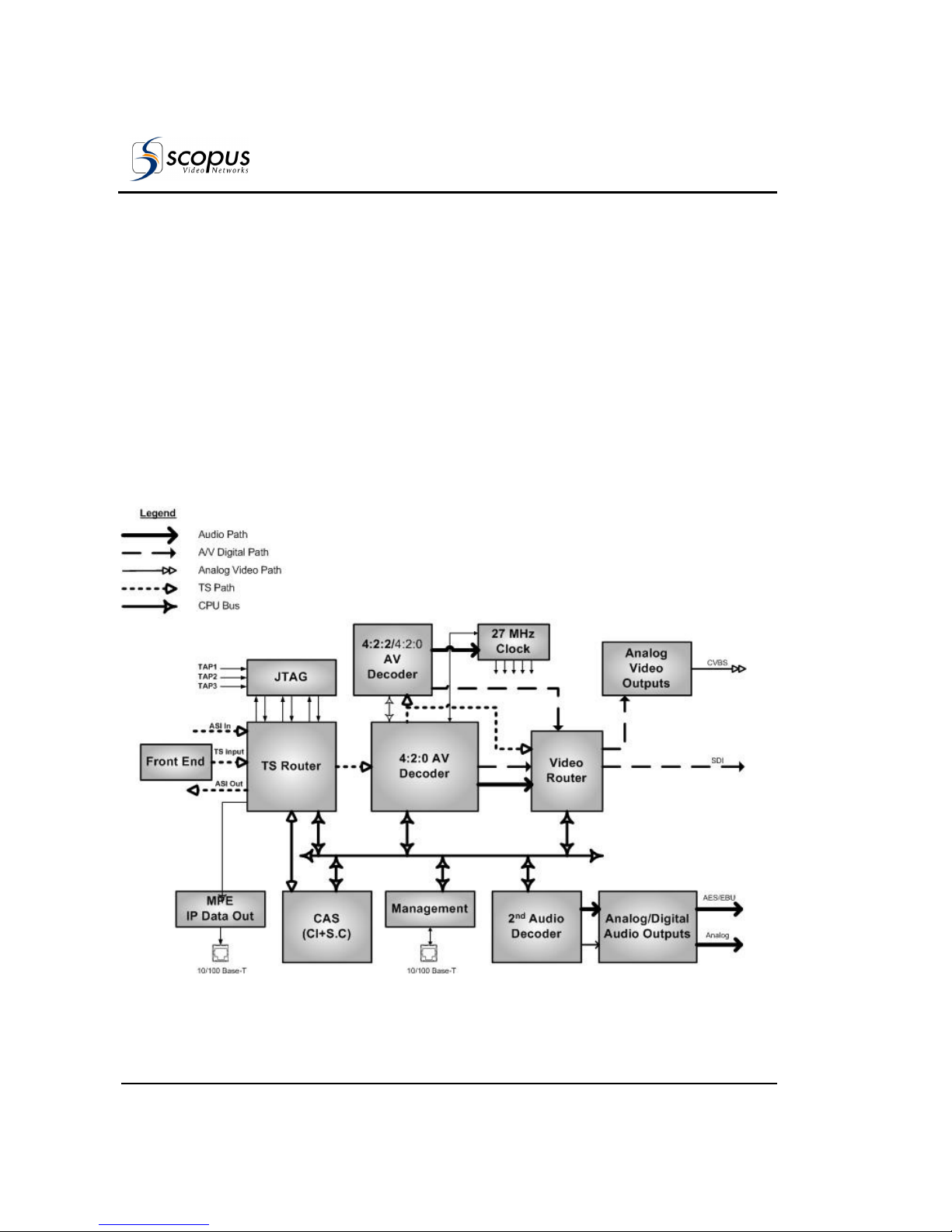
The TS Router block receives input streams from an available source, for
example: L-Band, MPEG-over-IP IN and ASI IN. Then the block routes the
selected input to the Master and Slave decoders. Each decoder decodes one
program from the input stream, routed by the TS router block, and provides
decoded digital audio and video streams. These streams are provided to the
Video Router block that routes them to the relevant outputs as well as to the
analog video output. The Analog Video Output receives a digital video, converts
the digital video into analog video, and outputs the analog video. The analog
and digital audio output component outputs the digital and analog audio.
Figure 1-1: Signal Path in the IRD-2900 – Functionality Block Diagram
Page 25
IRD-2900 Series
Professional Integrated Receiver Decoders
Scopus Documents (p/n 100793) Page 1-5
1.5. M
ECHANICAL STRUCTURE
The IRD-2900 is housed in a rugged industrial enclosure, 1RU by 19" (rack
mount).
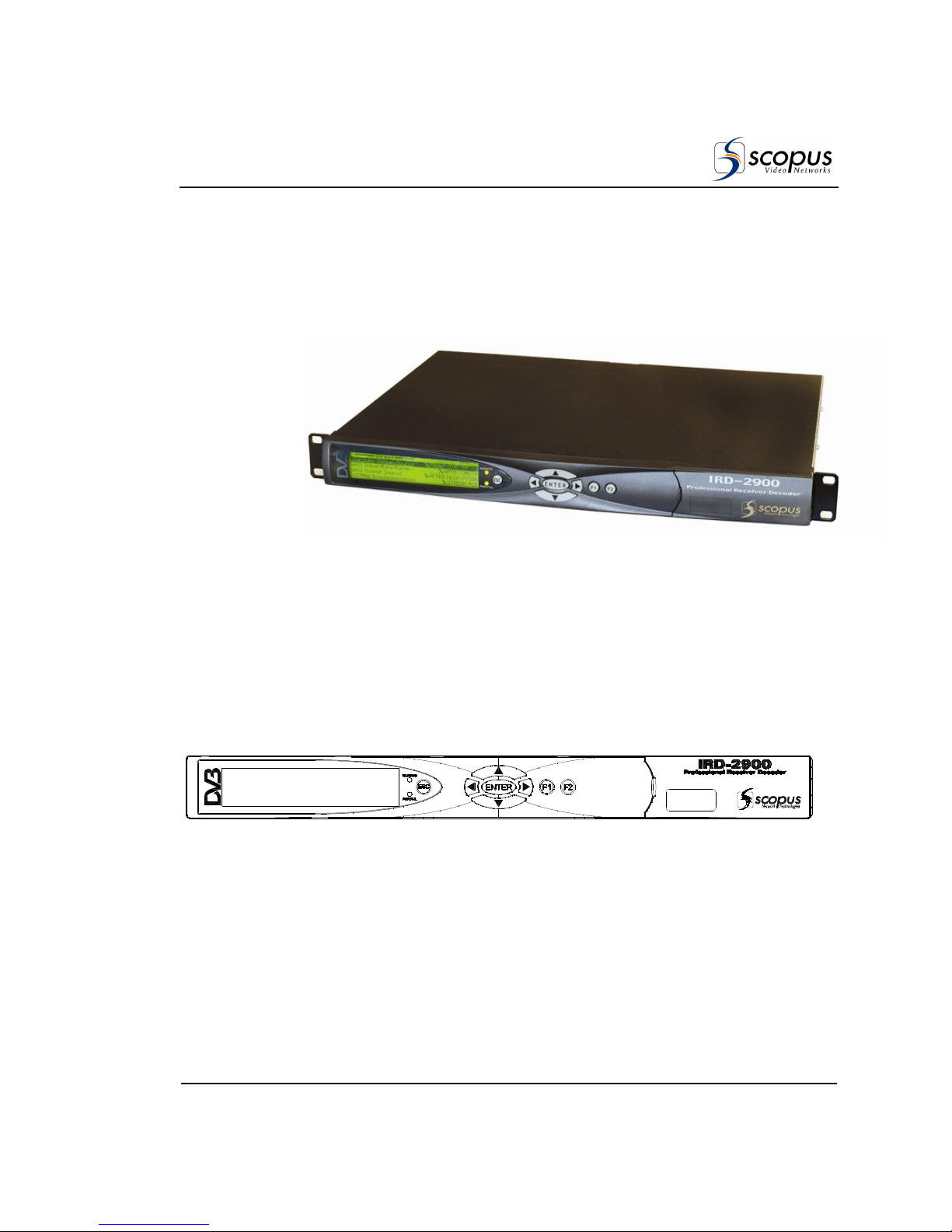
Figure 1-2: IRD-2900 Unit
1.5.1. Front Panel
The front panel allows control using a four-way touch pad, [Enter] key, [Esc]
key, and two programmable [F1]/[F2] keys. Operational commands and
parameters are displayed on a graphical LCD. The four-way touch pad allows
parameter modification and scrolling through the embedded VBI menus. Two
LEDs show the WARNING and PWR/FAIL status (see Figure 1-3).
Figure 1-3: Front View of the IRD
Page 26
User Manual
Overview
Page 1-6 (Rev. 4.6/ SW v1.80/ December 2007)
1.5.2. Various Front-Ends
IRD-2900 supports the following interfaces:
• DVB-S Single L-Band input
• DVB-S Dual L-Band input
• DVB-DSNG Dual L-Band input
• DVB-S2 Dual L-Band input
• MPEG over IP (MPEGoIP) dual input
• G.703 E3 single input with Loop-through
• ASI-In Decoder only (except for IRD-2960)
In this manual all rear panels are displayed with the DVB-S interface. Each
model has standard features and interfaces as well as features requiring active
software licenses.
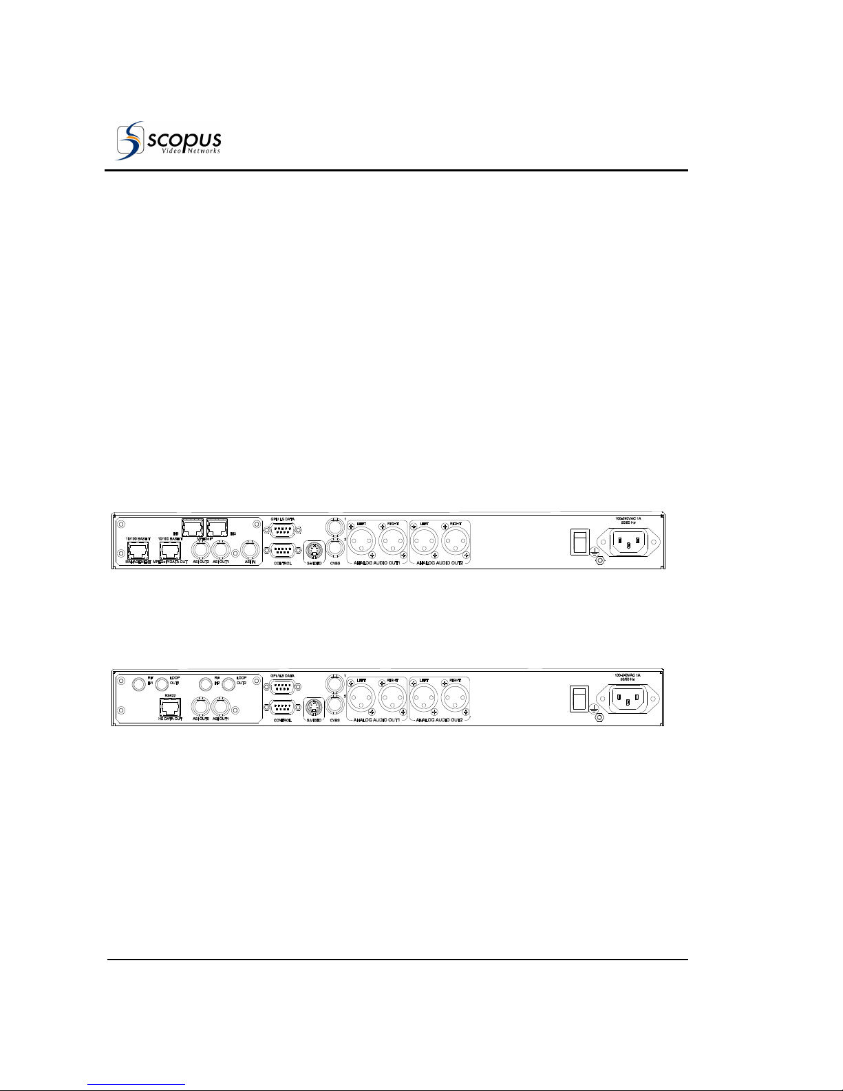
The MPEGoIP input interface can be supported by all IRD-2900 devices. Figure
1-4 illustrates the IRD-2961 rear panel with an MPEGoIP input interface.
Figure 1-4: IRD-2961 Rear Panel (IP Input interface)
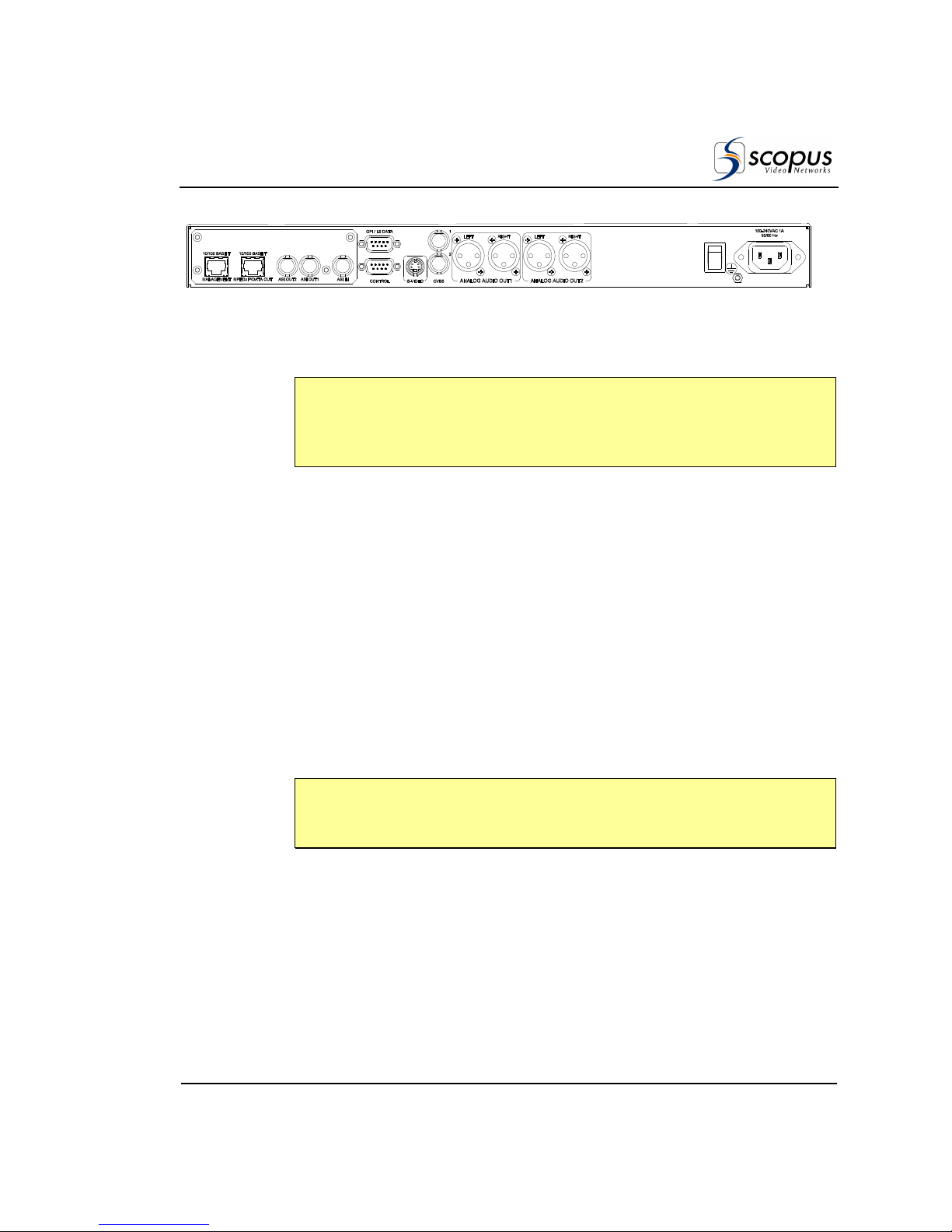
Figure 1-5 illustrates the IRD-2961 rear panel with DVB-S (QPSK) Dual Input
configuration.
Figure 1-5: IRD-2961 Rear Panel (DVB-S Dual Input interface)
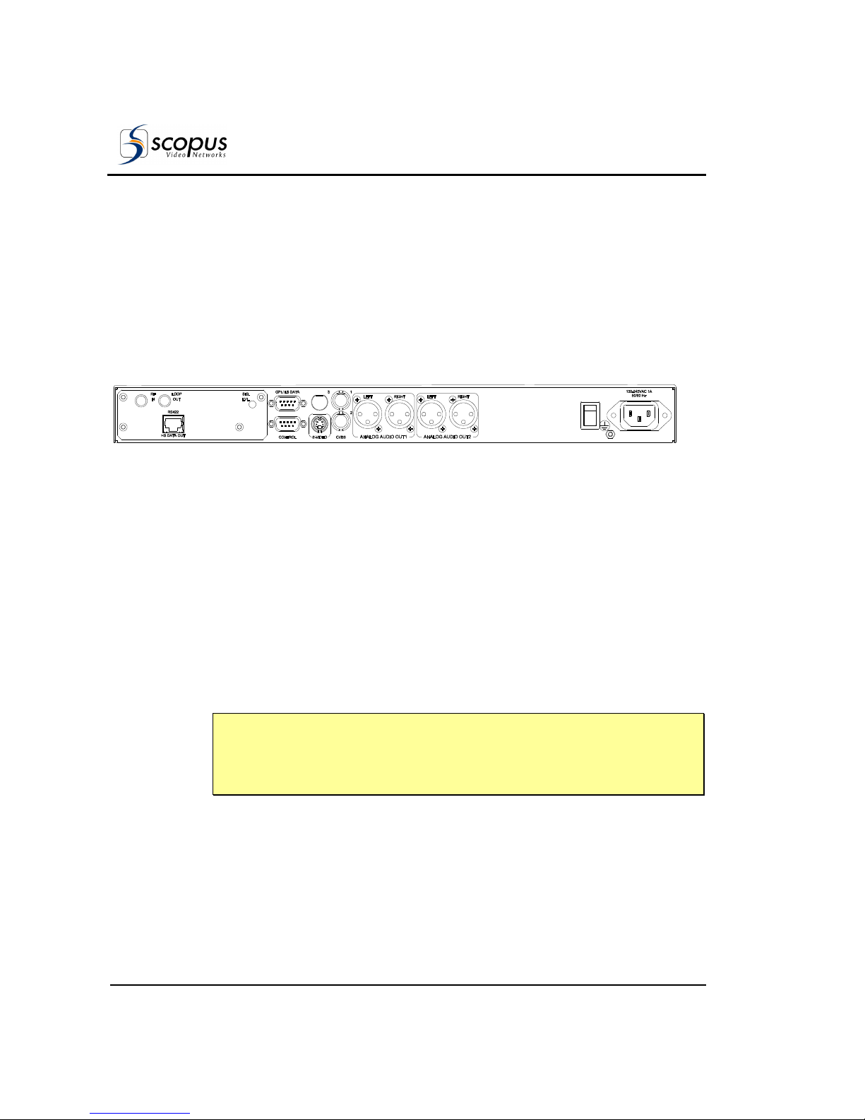
Figure 1-6 displays the IRD-2961 rear panel with Decoder Only configuration.
Page 27
IRD-2900 Series
Professional Integrated Receiver Decoders
Scopus Documents (p/n 100793) Page 1-7
Figure 1-6: IRD-2961 Rear Panel (Decoder Only interface)
N
OTE
IRD-2900 models supporting MPEGoIP output and IP data out (MPE
de-capsulation) output can be configured to support either MPEGoIP or IP data
out.
1.5.3. Software Permission (Licensing)
Each IRD-2900 model is provided with a basic feature package. In order to suit
specific requirements, additional license-permitted features are available. The
Next chapter specifies the basic and optional features available for each model.
In order to enable optional features perform one of the following:
• Upon unit ordering - order the relevant features. The unit will be
provided with the ordered features enabled.
• After unit ordering - order the relevant features. In this case, a 16
character key issued by Scopus video networks will be provided. The
key must be entered to the unit thru the front-panel or the webinterface. For details see section 4.2.11.6
N
OTE
When RS-232 low-speed-data and/or RS-422 high-speed-data are enabled
the PID Filtering is unavailable.
Page 28
User Manual
Overview
Page 1-8 (Rev. 4.6/ SW v1.80/ December 2007)
1.5.4. IRD-2900 models
1.5.4.1. IRD-2960 Interfaces and Features
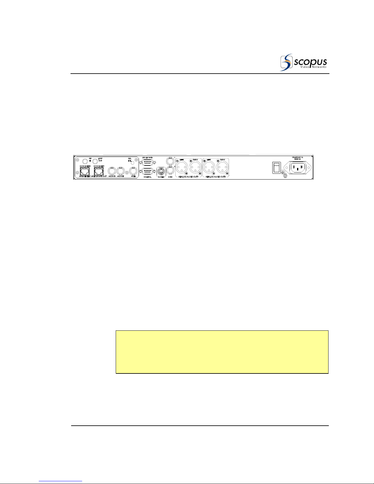
The IRD-2960 is a single 4:2:0 Decoder IRD. The IRD-296x devices consist of
two composite video interfaces. The CVBS #1 connector is used for broadcasting
quality video and the CVBS #2 connector is used for monitoring.
Figure 1-7 illustrates the IRD-2960 rear panel. The IRD-2960 basic features and
software-licensed features are also detailed.
Figure 1-7: IRD-2960 Rear Panel (Standard)
Basic Features
• 1 composite video - Broadcast
quality (upper connector)
• 1 composite video - Monitoring
quality (lower connector)
• 2 active analog – audio - stereo
balanced interfaces
• GPI
Software-Licensed Features
• Dolby digital (AC-3) LT/RT
downmixing
• RS-232 low speed data output
• RS-422 high speed data output
• H.264 (Scopus-Neotion module)
• DVB-S2 Advance Modulation
(optional)
N
OTES
The IRD-2960 does not support the Decoder Only configuration.
The Russian SECAM D/K (composite video only) is available only through Special
orders.
Page 29
IRD-2900 Series
Professional Integrated Receiver Decoders
Scopus Documents (p/n 100793) Page 1-9
1.5.4.2. IRD-2961 Interfaces and Features
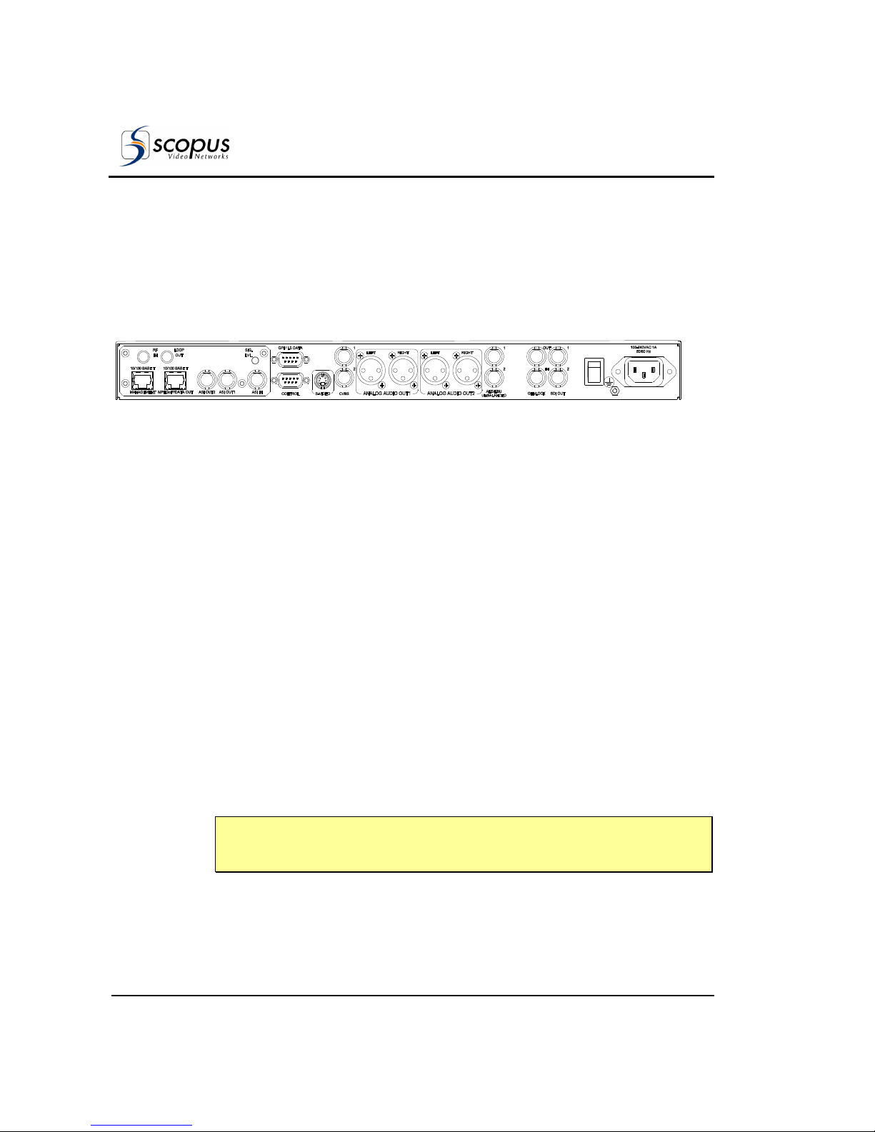
The IRD-2961 is a single 4:2:0 decoder IRD. The IRD-296x family consists of
two composite video interfaces. The CVBS #1 connector is used for broadcast
quality video and the CVBS #2 connector is used for monitoring.
Figure 1-8 illustrates the IRD-2961 rear panel. The IRD-2961 basic features and
software-licensed features are also detailed.
Figure 1-8: IRD-2961 Rear Panel
Basic Features
• 1 composite video - Broadcast
quality (upper connector)
• 1 composite video - Monitoring
quality (lower connector)
• 2 active analog – audio - stereo
balanced interfaces
• SNMP management (10/100 Base-T)
• Web based management
(10/100Base-T)
• GPI
Software-Licensed Features
• ASI Input
• Dual (identical) ASI outputs
• MPEG-over-IP output or IP data
output (MPE de-capsulation)
• Dolby Digital (AC-3) LT/RT
downmixing
• Pro MPEG FEC
• IP Dual input (link and source
redundancy
• PID and service filtering
• RS-232 low speed data output
• H.264 (Scopus-Neotion module)
• DVB-S2 Advance Modulation
(optional)
N
OTES
In the case of power failure or system shutdown, ASI OUT 1 output will become
ASI loop-through. Use ASI OUT 1 output for cascading a chain of IRD-2900.
The Russian SECAM D/K (composite video only) is available only through special
orders.
Page 30
User Manual
Overview
Page 1-10 (Rev. 4.6/ SW v1.80/ December 2007)
1.5.4.3. IRD-2962 Interfaces and Features
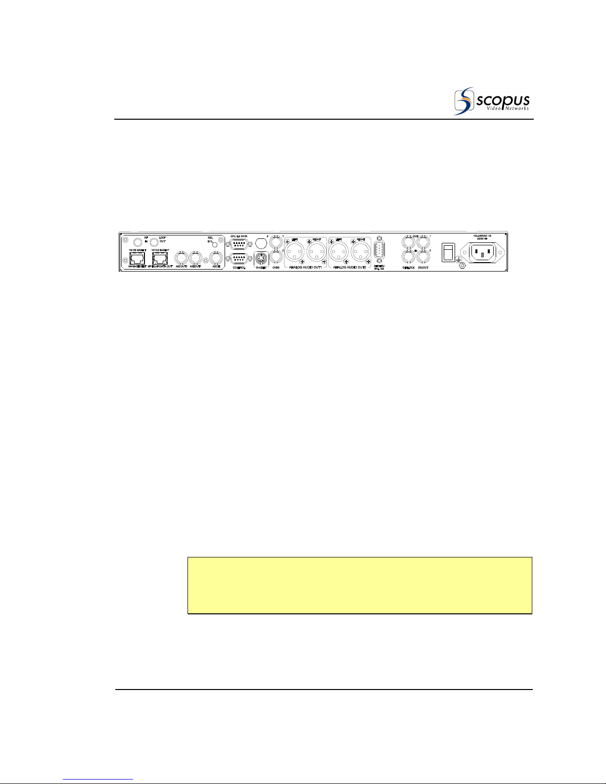
The IRD-2962 is a single 4:2:0 decoder. The entire IRD-296x family consists of
two composite video interfaces. The CVBS #1 connector is used for broadcast
quality video and the CVBS #2 connector can is for monitoring.
Figure 1-9 illustrates the IRD-2962 rear panel. The IRD-2962 basic features and
software-licensed features are also detailed.
Figure 1-9: IRD-2962 Rear Panel
Basic Features
• 1 composite video - Broadcast
quality (upper connector)
• 1 composite video - Monitoring
quality (lower connector)
• 2 SDI interfaces
• Embedded VBI and up to 2 stereo
channels in SDI
• 2 activated analog-audio-stereo
balanced interfaces
• 2 activated AES/EBU-SPDIF audiounbalanced interfaces
• SNMP management (10/100 Base-T)
• Web-based management (10/100
Base-T)
• GPI
• Front panel A/V monitoring
connectors
Software-Licensed Features
• ASI Input
• Dual (identical) ASI outputs
• MPEG-over-IP output or IP data
output (MPE de-capsulation)
• Genlock input and loop-through
output
• Dolby Digital (AC-3) LT/RT
downmixing.
• Pro MPEG FEC
• PID and service filtering
• H.264 (One Program Only)
• RS-232 low speed data output
• H.264 (Scopus-Neotion module)
• DVB-S2 Advance Modulation
(optional)
N
OTE
In the case of power failure or system shutdown, ASI OUT 1 output will become
ASI loop-through. Use ASI OUT 1 output for cascading a chain of IRD-2900.
Page 31
IRD-2900 Series
Professional Integrated Receiver Decoders
Scopus Documents (p/n 100793) Page 1-11
1.5.4.4. IRD-2963 Interfaces and Features
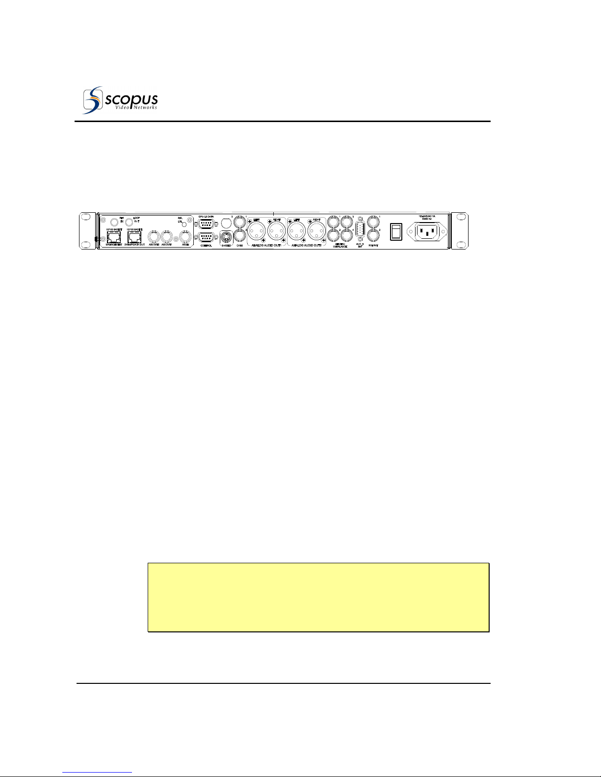
The IRD-2963 is a single 4:2:0 decoder. The entire IRD-296X family consists of
two composite video interfaces. The CVBS #1 connector is used for broadcast
quality video and the CVBS #2 connector is used for monitoring.
Figure 1-10 illustrates the IRD-2963 rear panel. The IRD-2963 basic features
and software-licensed features are described below.
Figure 1-10: IRD-2963 Rear Panel
Basic Features
• 1 composite video - Broadcast
quality (upper connector)
• 1 composite video - Monitoring
quality (lower connector)
• 2 SDI interfaces
• Embedded VBI and up to 2 stereo
channels in SDI
• 2 active analog-audio-stereo
balanced interfaces
• 2 active AES/EBU-SPDIF audiobalanced interfaces
• SNMP management (10/100 Base-T)
• Web-based management (10/100
Base-T)
• GPI
• Front panel A/V monitoring
connectors
Software-Licensed Features
• ASI input
• Dual (identical) ASI output
• MPEG-over-IP output or IP data
output (MPE de-capsulation)
• Genlock input and loop-through
output
• Dolby Digital (AC-3) LT/RT
downmixing
• Pro MPEG FEC
• IP Dual input (link and source
redundancy
• PID and service filtering
• RS-232 low speed data output
• H.264 (Scopus-Neotion module)
• DVB-S2 Advance Modulation
(optional)
N
OTES
This model requires a breakout cable to connect to the AES/EBU interfaces.
In case of power failure or system shutdown, ASI OUT 1 output will become ASI
loop-through. Use ASI OUT 1 output for cascading a chain of IRD-2900
Page 32
User Manual
Overview
Page 1-12 (Rev. 4.6/ SW v1.80/ December 2007)
1.5.4.5. IRD-2980 Interfaces and Features
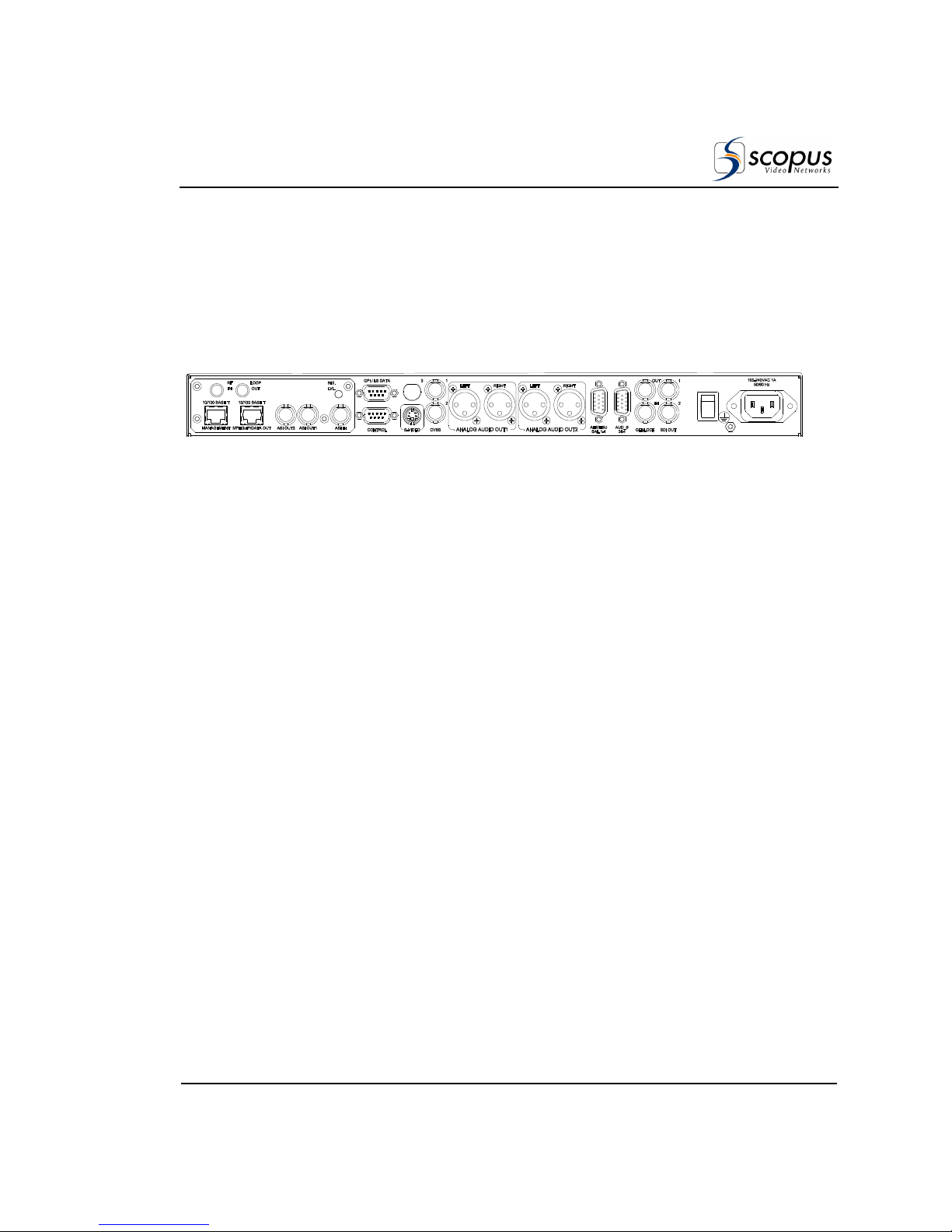
The IRD-2980 is a single 4:2:0/4:2:2 decoder. The IRD-298x family consists
of two composite video interfaces. Both CVBS #1 and CVBS #2 connectors are
for broadcast quality video. Figure 1-11 illustrates the IRD-2980 rear panel. The
IRD-2980 basic and software-licensed features are also detailed.
Figure 1-11: IRD-2980 Rear Panel
Basic Features
• 2 composite video interfaces –
Broadcast quality
• 2 SDI interfaces
• Embedded VBI and up to 4
stereo channels in SDI
• Decoding 4:2:2 PP@ML (1.5–50
Mbps)
• 2 out of 4 active analog-audiostereo balanced interfaces
• 2 out of 4 active AES/EBU-SPDIF
audio unbalanced interfaces
• 1ST and 2ND active AES/EBU-
SPDIF
• SNMP management (10/100
Base-T)
• Web-based management (10/100
Base-T)
• GPI
• Front panel A/V monitoring
connectors
Software-Licensed Features
• ASI input
• Dual (identical) ASI output
• MPEG-over-IP output or IP data
output (MPE de-capsulation)
• 3RD Active analog stereo pair
• 4TH Active analog stereo pair
• 3RD Active AES/EBU-SPDIF
• 4TH Active AES/EBU-SPDIF
• Dolby Digital (AC-3) LT/RT
downmixing
• Linear PCM (SMPTE 302M 2000),
Dolby-E pass-through
• Pro MPEG FEC
• IP Dual input (link and source
redundancy
• PID and service filtering
• RS-232 low speed data output
• DVB-S2 Advance Modulation
(optional)
N
OTES
This model requires a breakout cable to connect to the 3rd and 4th analog stereo
pairs.
In the case of power failure or system shutdown, ASI OUT 1 output will become
ASI loop-through. Use ASI OUT 1 output for cascading a chain of IRD-2900.
Page 33
IRD-2900 Series
Professional Integrated Receiver Decoders
Scopus Documents (p/n 100793) Page 1-13
1.5.4.6. IRD-2981 Interfaces and Features
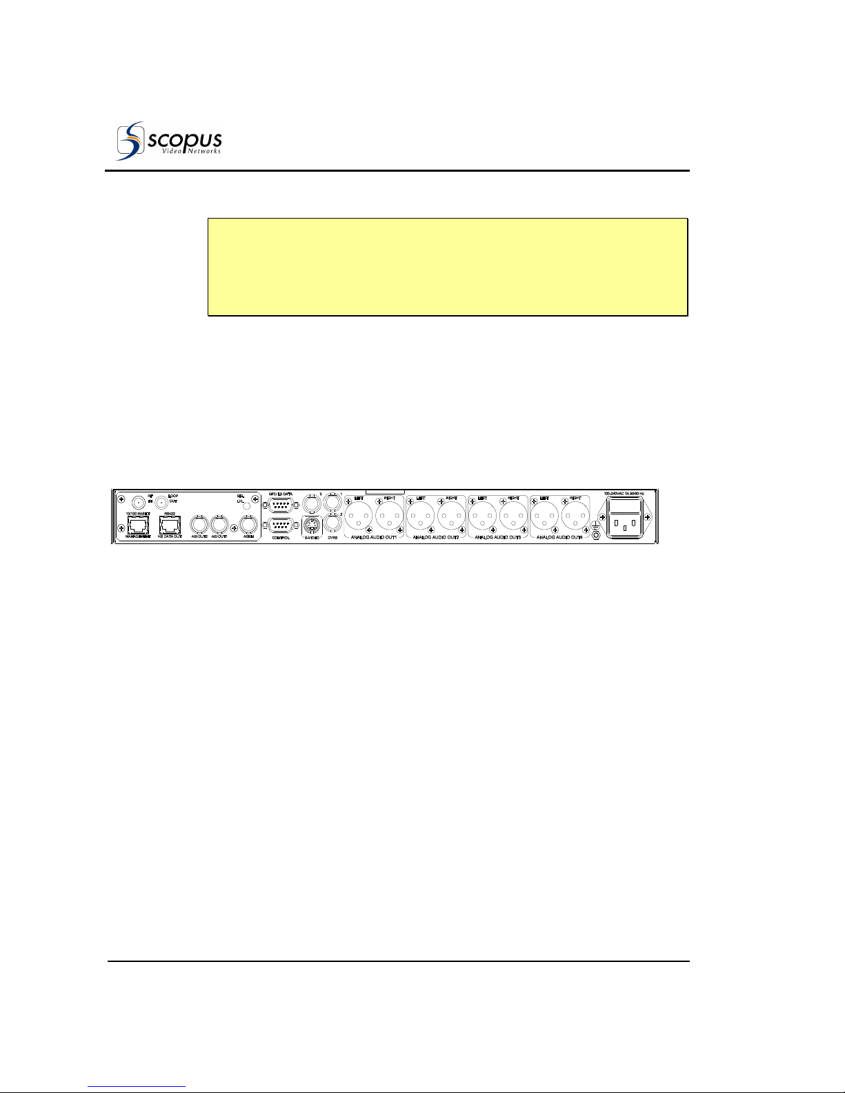
The IRD-2981 is a single 4:2:2 decoder. The IRD-298x family consists of two
composite video interfaces. Both CVBS interfaces are for service broadcast video
quality.
Figure 1-12 illustrates the IRD-2981 rear panel. The IRD-2981 basic and
software-licensed features are also detailed.
Figure 1-12: IRD-2981 Rear Panel
Basic Features
• 2 composite video interfaces –
Broadcast quality
• 2 SDI interfaces
• Embedded VBI and up to 4 stereo
channels in SDI
• Decoding 4:2:2 PP@ML (1.5–50
Mbps)
• 2 out of 4 active analog-audio-stereo
balanced interfaces
• 2 out of 4 active AES/EBU-SPDIF
audio-balanced interfaces
• Genlock input and loop-through
output
• SNMP management (10/100 Base-T)
• Web-based management (10/100
Base-T)
• GPI
• Front panel A/V monitoring
connectors
Software-Licensed Features
• ASI input
• Dual (identical) ASI output
• MPEG-over-IP output or IP data
output (MPE de-capsulation)
• 3rd Active analog stereo pair
• 4th Active analog stereo pair
• 3rd Active AES/EBU-SPDIF
• 4th Active AES/EBU-SPDIF
• Dolby Digital (AC-3) LT/RT
downmixing
• Linear PCM (SMPTE 302M 2000),
Dolby-E pass-through
• Genlock input and loop-through
output
• Dolby Digital (AC-3) LT/RT
downmixing.
• Pro MPEG FEC
• PID and service filtering
• H.264 (One Program Only)
• RS-232 low speed data output
• DVB-S2 Advance Modulation
(optional)
Page 34
User Manual
Overview
Page 1-14 (Rev. 4.6/ SW v1.80/ December 2007)
N
OTES
This model requires a breakout cable to connect to the AES/EBU interfaces and
to connect to the 3rd and 4th analog stereo pairs.
In the case of power failure or system shutdown, ASI OUT 1 output will become
ASI loop-through. Use ASI OUT 1 output for cascading a chain of IRD-2900.
1.5.4.7. IRD-2990 Interfaces and Features
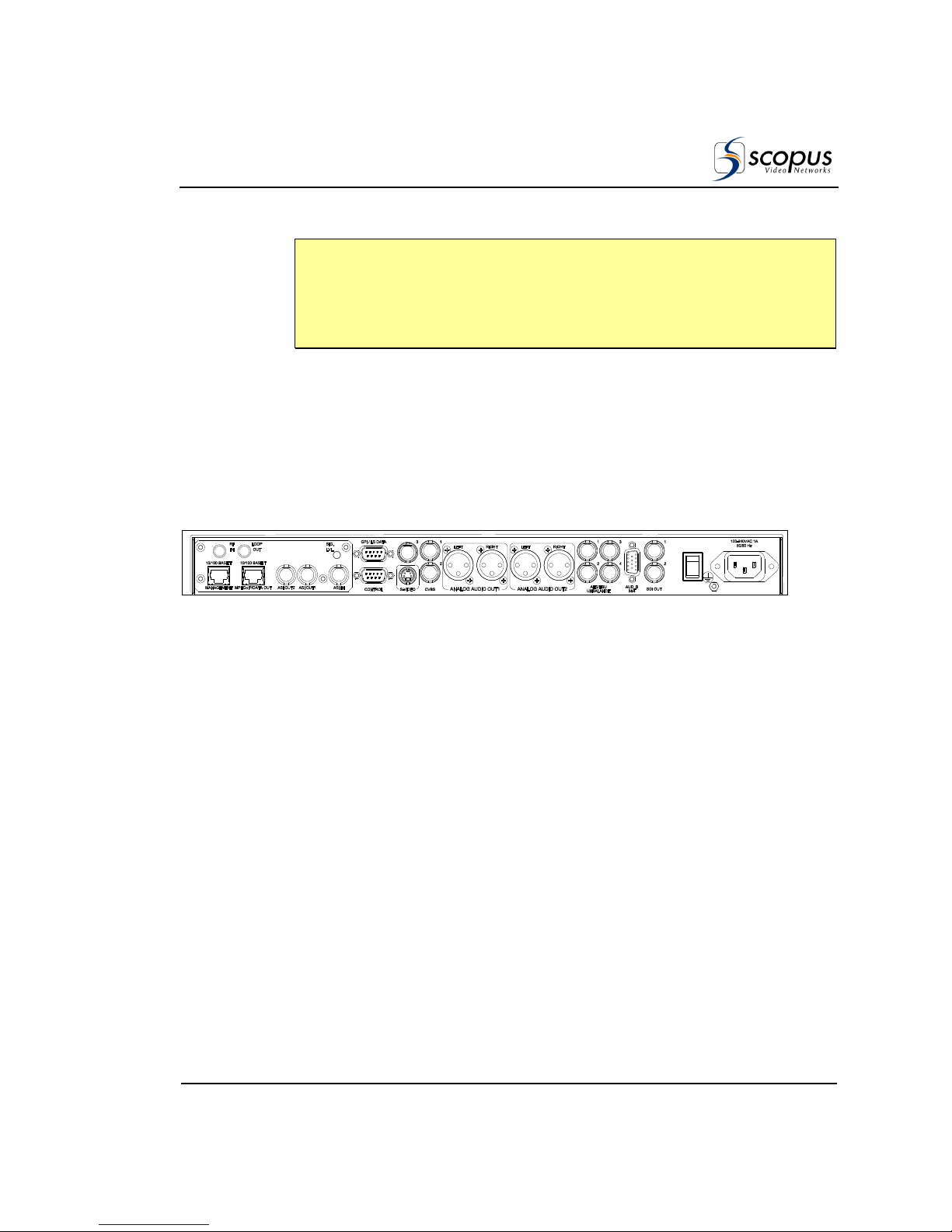
The IRD-2990 is a dual 4:2:0 decoder. The IRD-299x family consists of three
composite video interfaces. The CVBS #1 connector is for the broadcast quality
video of decoder #1. The CVBS #2 is used for monitoring. The CVBS #3
connector is for the broadcast quality video of decoder #2.
Figure 1-13 illustrates the IRD-2990 rear panel. The IRD-2990 basic and
software-licensed features are also detailed.
Figure 1-13: IRD-2990 Rear Panel
Basic Features
• 1 composite video for program 1- Broadcast
quality (upper-right connector)
• 1 composite video for program 2 Broadcast quality (upper-left connector)
• 1 composite video for program 1Monitoring quality (lower connector)
• 4 active analog-audio-stereo balanced
interfaces
• SNMP management (10/100 Base-T)
• Web-based management (10/100 Base-T)
• RS-422 high speed data output
• GPI
Software Licensed Features
• ASI input
• Dual (identical) ASI output
• Dolby Digital (AC-3) LT/RT
downmixing
• H.264 (One program only)
• RS-232 low speed data output
• RS-422 high speed data output
• DVB-S2 Advance Modulation
(optional)
Page 35
IRD-2900 Series
Professional Integrated Receiver Decoders
Scopus Documents (p/n 100793) Page 1-15
N
OTE
In the case of power failure or system shutdown, ASI OUT 1 output will become
ASI loop-through. Use ASI OUT 1 output for cascading a chain of IRD-2900.
The Russian SECAM D/K (composite video only) is available only through special
orders.
1.5.4.8. IRD-2991 Interfaces and Features
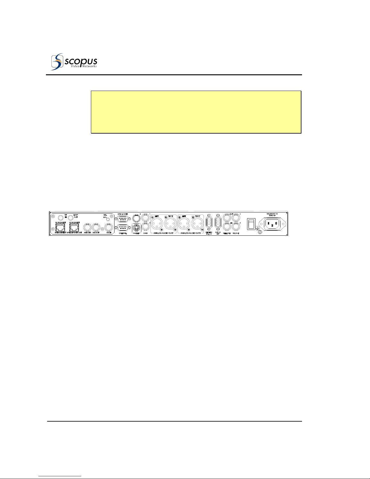
The IRD-2991 is a dual 4:2:0 decoder. The IRD-299x family consists of three
composite video interfaces. The CVBS #1 connector is for the broadcast quality
video of decoder #1. The CVBS #2 is used for monitoring. The CVBS #3
connector is for broadcast quality video of decoder #2.
Figure 1-13 illustrates the IRD-2991 rear panel. The IRD-2991 basic features
and software-licensed features are also detailed.
Figure 1-14: IRD-2991 Rear Panel
Basic Features
• 3 composite video interfaces (2 for
broadcast, 1 for monitoring)
• 2 SDI interfaces
• Embedded VBI and up to 4 stereo
channels in SDI
• 4 active analog-audio-stereo
balanced interfaces
• 4 active AES/EBU-SPDIF audio
unbalanced interface
• SNMP management (10/100
Base-T)
• Web-based management (10/100
Base-T)
• GPI
Software-Licensed Features
• ASI input
• Dual (identical) ASI output
• MPEG-over-IP output or IP data
output (MPE de-capsulation)
• Dolby Digital (AC-3) LT/RT
downmixing
• Linear PCM (SMPTE 302M 2000),
Dolby-E pass-through.
• Pro MPEG FEC
• H.264 (One program only)
• PID and service filtering
• RS-232 low speed data output
• DVB-S2 Advance Modulation
(optional)
Page 36
User Manual
Overview
Page 1-16 (Rev. 4.6/ SW v1.80/ December 2007)
N
OTES
This model requires a breakout cable to connect to the 3rd and 4th analog
stereo pairs.
In case of power failure or system shutdown, ASI OUT 1 output will become ASI
loop-through. Use ASI OUT 1 output for cascading a chain of IRD-2900.
1.5.4.9. IRD-2992 Interfaces and Features
The IRD-2992 is a dual 4:2:0 decoder. The IRD-299x family consists of three
composite video interfaces. The CVBS #1 is for service broadcast video quality.
The CVBS #2 is for service monitoring and OSD video quality. The CVBS #3 is
for additional service broadcast video quality.
Figure 1-15 illustrates the IRD-2992 rear panel. The IRD-2992 basic features
and software-licensed features are also detailed.
Figure 1-15: IRD-2992 Rear Panel
Basic Features
• 3 composite video interfaces (2 for
broadcast, 1 for monitoring)
• 2 SDI interfaces
• Embedded VBI and up to 4 stereo
channels in SDI
• 4 active analog-audio-stereo
balanced interfaces
• 4 active AES/EBU-SPDIF audio
balanced interfaces
• SNMP management (10/100 BasT)
• Web-based management (10/100
Base-T)
• GPI
Software-Licensed Features
• ASI input
• Dual (identical) ASI output
• MPEG-over-IP output or IP data
output (MPE de-capsulation)
• Genlock input and loop-through
output
• Dolby Digital (AC-3) LT/RT
downmixing
• Linear PCM (SMPTE 302M 2000),
Dolby-E pass-through
• Pro MPEG FEC
• H.264 (One program only)
• PID and service filtering
• RS-232 low speed data output
• DVB-S2 Advance Modulation
(optional)
Page 37

IRD-2900 Series
Professional Integrated Receiver Decoders
Scopus Documents (p/n 100793) Page 1-17
N
OTES
This model requires a breakout cable to connect to the AES/EBU interfaces and
to connect to the 3rd and 4th analog stereo pairs.
In the case of power failure or system shutdown, ASI OUT 1 output will become
ASI loop-through. Use ASI OUT 1 output for cascading a chain of IRD-2900
1.6. M
ANAGEMENT
The following sections detail the different management interfaces and methods
available to control the iRD-2900
1.6.1. Local Management
The IRD-2900 supports two local management methods:
• Front Panel Control - The IRD-2900 front panel provides an easy to use
graphical display with a large LCD screen and intuitive control.
• PC Terminal Control - The IRD-2900 supports PC terminal control from a
standard PC terminal (over RS-232 or RS-485). The terminal provides
access to control and monitor functionalities that are not available when
using any IRD-2900 front panel feature.
1.6.2. Remote Management
IRD-2900 supports three remote management methods:
• NMS-4000 and Future NMS-7000 - The NMS-4000 Network Management
System enables management of the IRD-2900 through the transmission link.
The NMS-4000 provides a menu and dialog-driven interface from which
control, modification, and upgrade operations can be performed on the IRD.
• Web-Based Management - IRD-2900 supports web-based management.
Managing IRD-2900 parameters using web-based control is as easy as pointand-click.
• Telnet - The IRD-2900 supports remote control throughout the Internet.
The IRD-2900 can be controlled and configured from a standard PC terminal
(over Ethernet). The terminal provides access to control and monitor
functionalities that are not available when using any IRD-2900 front panel
feature.
Page 38

User Manual
Overview
Page 1-18 (Rev. 4.6/ SW v1.80/ December 2007)
1.7. C
HARACTERISTICS AND
S
PECIFICATIONS
The following section provides with the IRD-2900 Characteristics and
specification.
1.7.1. Transport Stream Interface
Options
F
EATURE
S
PECIFICATIONS
DVB-S
S
INGLE INPUT
• Interface - F-type 75Ω
• Constellation - QPSK
• Single L-band input
• Frequency range - 950-2150 MHz
• RF Input level: (-65) – (-25) dBm
• Symbol rate range - 1-45M Sym/s
• L-Band RF input with LNB control and loop-through
output
DVB-S
D
UAL INPUT
• Interface - F-type 75Ω
• Constellation - QPSK
• Dual L-band input
• Dual independent demodulators
• Manual selection between inputs
• Frequency range - 950-2150 MHz
• Symbol rate range - 1-45M Sym/s
• L-Band RF input with LNB control and loop-through
output
Page 39

IRD-2900 Series
Professional Integrated Receiver Decoders
Scopus Documents (p/n 100793) Page 1-19
F
EATURE
S
PECIFICATIONS
DVB-DSNG
S
INGLE INPUT
• Interface - F-type 75Ω
• Constellation – QPSK, 8PSK and 16QAM
• Single L-band input
• Frequency range - 950-2150 MHz
• Symbol rate range - 1-45M Sym/s
• L-Band RF input with LNB control and loop-through
output
DVB-S2
S
INGLE INPUT
• Applications - Broadcast services and DSNG EN 302
307
• Mode – CCM, ACM
• Constellations: QPSK, 8PSK, 16APSK
• FEC frames: Normal (64800 bits), short (16200 bits)
• Roll-Off: 0.35, 0.25, 0.20
• Pilots – On, Off
• Frequency range: 950 MHz - 2150 MHz
• Symbol rate range – 1Msym/s - 45Msym/s
• 2 L-Band RF 75Ω inputs with LNB control
• Modulation Scheme Recovery: Automatic (ACM
mode)
• Physical Layer Scrambling support
• Multiple input transport stream (MSI) support using
Input Stream Identifier (ISI)
Page 40

User Manual
Overview
Page 1-20 (Rev. 4.6/ SW v1.80/ December 2007)
F
EATURE
S
PECIFICATIONS
MPEGOIP I
NPUT
• Two physical links - 10/100 Base-T, RJ-45 – one
active at a time
• Two logical sources (sockets) – one active at a time
• Physical Link and logical source redundancy
(coupled)
• De-Jittering buffer size - configurable
100-2000mSec
• TS bit rate: up to 44 Mbps
• Encapsulation type: UDP and RTP (Automatic
detection)
• SPTS/MPTS
• Unicast/Multicast
• IGMPv2
• Forward Error Correction (FEC)
• ProMPEG CoP3v2
• Maximum input bit-rate: 25Mb/s
• Columns only FEC protection
• Matrix dimensions - Columns 1-20, Rows 4-20.
Columns*Rows ≤ 100 (Automatic detection)
MPEGOIP
OUTPUT
• TS bit rate - up to 60 Mbps
• SPTS/MPTS
• Encapsulation - UDP
• All programs and PIDs are present in the output TS
• Interface 10/100 Base-T, RJ-45
DVB-ASI I
NPUT
• Interface: copper, BNC 75 ohm
• TS bit rate: up to 100 Mbps (Byte and Burst mode)
Page 41

IRD-2900 Series
Professional Integrated Receiver Decoders
Scopus Documents (p/n 100793) Page 1-21
F
EATURE
S
PECIFICATIONS
DVB-ASI O
UTPUT
• 2 ASI connectors: copper, BNC 75 ohm
• ASI options:
• ASI OUT 1 - output stream with decrypted
selected program, output stream and loopthrough
• ASI OUT 2 - output stream with decrypted
selected program, output stream
• ASI output rate - up to 100 Mbps (Byte mode)
T
ELECOM
G.703
I
NPUT
• Unframed PDH Data rates::E1,E2 or E3
• FEC (optional): DVB-C FEC
• Loop-through output
DVB-PDH I
NPUT
• Interface: ATM AAL-1
• Data rates: DS3 or E3
• Loop-through output
1.7.2. Advanced Processing
F
EATURE
S
PECIFICATIONS
S
ERVICE AND
PID
F
ILTERING
• Active on ASI and IP outputs
• PCR re-stamping
• VBR and CBR modes (NULL stuffing)
• Forward only and filter only modes
• Dynamic Service filtering (tracks PIDs'
modifications)
• Static PID filtering
• PSI/SI tables are not modified.
Page 42
User Manual
Overview
Page 1-22 (Rev. 4.6/ SW v1.80/ December 2007)
F
EATURE
S
PECIFICATIONS
D
ATA
• High speed data: RS-422 Up to 20 Mbps, RJ-45
(supported by IRD-2960, IRD-2990)
• IP Data Out (RJ-45): up to 60Mbps (MPE decapsulation)
1.7.3. Decoder Outputs
F
EATURE
S
PECIFICATIONS
V
IDEO
• Video Formats:
• PAL-B/G/I/M/N/D, NTSC, SECAM L/B/G/K1
• Russian SECAM D/K (composite video only
supported only by special order in IRD-2960,
IRD-2961 and IRD-2990)
• Decoding:
• 4:2:0 MP@ML (1.5 – 15 Mbps)
• 4:2:2 PP@ML (1.5 – 50 Mbps) (supported only
in IRD298x)
• Maximum TS decoding bit rate: 108Mbps
• Video resolution interpolation: Pan-scan, letter box
or Pass through
• Aspect ratios: 4:3/16:9
• Aspect ratio 14:9 by signaling over VBI video index
• Graphical processing (OSD): DVB subtitling, EBU
(Teletext) subtitling
• OSD only through monitoring output
• Genlock input and loop-through output and phase
compensation (supported only by IRD2962,
IRD2963, IRD2981 and IRD2992)
• Genlock Sync lock resolution: +/- 37nSec
Page 43

IRD-2900 Series
Professional Integrated Receiver Decoders
Scopus Documents (p/n 100793) Page 1-23
F
EATURE
S
PECIFICATIONS
H.264
Based on Scopus-Neotion CAM module
Video Characteristics:
• Video decoding standard: H.264 part 10
• Profile: Full D1 Main Profile up to Level 3.0 (one
4:2:0 service)
• Video Format: PAL & NTSC
• Video bit-rate: CBR only
• Picture aspect ratio: 4:3 and 16:9
Transport-Stream characteristics:
• Maximum Transport-stream BW: 40Mb/s
• Minimum Transport stream stuffing: 200Kb/s
• PCR should be included in the video PID
F
RONT PANEL
M
ONITORING
• Video monitor output connector (Supported only by
298x)
• Audio monitor output connector (Supported only by
298x)
VBI RE-
INSERTION
• All VBIs adhere the relevant standards including
the line numbers
• In composite video and embedded SDI
• WST Teletext and inverted Teletext
• WSS, VPS, VITC, CC, AMOL I, AMOL II (Nielsen),
TV-Guide, V-CHIP
• Enhanced VITS with built-in generator
Page 44

User Manual
Overview
Page 1-24 (Rev. 4.6/ SW v1.80/ December 2007)
F
EATURE
S
PECIFICATIONS
A
UDIO
• Modes: stereo, joint stereo, dual channel, single
channel
• Analog max output level: +18 dBu @ 600Ω
• Digital max output level: 0 dBFs
• Attenuation control at -64 dB to 0 dB and mute
• Dolby Digital (AC-3) Pass-through
• Dolby Digital (AC-3) LT/RT downmixing
• Linear PCM (SMPTE 302M 2000) supported over
analog and digital outputs 2/3/4 (supported in
IRD2980, IRD2981, IRD2991, IRD2992)
• Dolby-E pass-through supported over digital
outputs 2/3/4 (supported in IRD2980, IRD2981,
IRD2991, IRD2992)
Page 45

IRD-2900 Series
Professional Integrated Receiver Decoders
Scopus Documents (p/n 100793) Page 1-25
1.7.4. Conditional Access
F
EATURE
S
PECIFICATIONS
E
MBEDDED
DVB-
D
ESCRAMBLING
• BISS mode-1
• BISS-E
• CAS-5000
DVB-CI
• Interface – 2 CI slots EN-50221 (Only 1 active
simultaneously)
• Maximum of decrypted programs - 1 for single
decoder, and 2 for dual decoder (in case the
specific CAM supports it).
• Maximum TS bitrate – 72 Mbps
• CA methods: Multicrypt, Simulcrypt
• CASs: Viaccess®, Irdeto®, Conax®,
MediaGuard®, Nagravision®, Cryptoworks®,
VideoGuard®, OnDigital®, CODICrypt®
1.7.5. Control and Monitoring
F
EATURE
S
PECIFICATIONS
L
OCAL
• Graphical easy-to-use front panel
• Advanced satellite scanning (CLI support only)
• Operates in service and PID modes
• 2 GPI dry contacts for various status and fault
indications
E
NHANCED
DVB
M
ONITORING
• Front panel display: signal quality, Eb/N0, BER,
ASI format, network and service information, CA
information, CI slots, video and audio decoded
information
Page 46
User Manual
Overview
Page 1-26 (Rev. 4.6/ SW v1.80/ December 2007)
R
EMOTE
• SNMP management
• Web-based management
• Telnet
• Terminal via RS-232 or RS-485
• Software download
O
VER THE AIR
• Software download
1.7.6. Compliance
F
EATURE
S
PECIFICATIONS
EMC
• EN55013 (CISPR 13)
• EN55020 (CISPR 20)
• EN55022 (CISPR 22)
• EN55024 (CISPR 24)
• FCC part 15 (Class B)
S
AFETY
• EN60950
• CB (IEC60950)
• UL60950
• cTUVus
1.7.7. Environmental Conditions
F
EATURE
S
PECIFICATIONS
O
PERATION
• Temperature - 0°C - 50°C
• Humidity - 5% - 90% (non-condensing)
S
TORAGE AND
T
RANSPORTATION
• Temperature - -40°C - 70°C
• Humidity - 0% - 95% (non-condensing)
Page 47

IRD-2900 Series
Professional Integrated Receiver Decoders
Scopus Documents (p/n 100793) Page 1-27
1.7.8. Physical and Power
Specifications
F
EATURE
S
PECIFICATIONS
P
HYSICAL
• 1RU unit, 19’’ rack mountable
• Dimensions (HxWxD) –
1RU X 19” X 14”/44mm X 482.6mm X 357mm
• Weight – 3.5Kg. (7.7lbs).
P
OWER
• Voltage:
• 100 - 240V AC, 50/60Hz
• Power consumption – up to 50w max
Page 48

Page 49

IRD-2900 Series
Professional Integrated Receiver Decoders
Scopus Documents (p/n 100793) Page 2-1
Chapter 2.
I
NSTALLATION
This section details the safety precautions and inventory check when installing
the IRD-2900 Series.
2.1. S
AFETY PRECAUTIONS
To avoid injury and prevent equipment damage, observe the following safety
precautions:
• Do not move or ship equipment unless it is correctly packaged in its original
wrapping and shipping containers.
• Only Scopus trained personnel can perform service and maintenance.
• To prevent lightning damage, ground the unit according to local regulations.
• Do not permit unqualified personnel to operate the unit.
2.1.1. Restricted Access Area
The DC powered equipment should only be installed in a Restricted Access Area
2.1.2. Installation Codes
This device must be installed according to national electrical codes. For North
America, equipment must be installed in accordance with the US National
Electrical Code, Articles 110-16, 110-17, and 110-18 and the Canadian Electrical
Code, Section 12.
Add Markings for AC units for Denmark, Finland, and Sweden (marked on
product):
• Denmark- “Unit is class I, unit shall be used with an AC cord set suitable
with Denmark deviations. Cord shall including an earthing conductor. Unit
shall be plugged into a wall socket outlet which connected to protective
earth. Socket outlets which are not connected to earth shall not be used!”
• Finland - (Marking label and in manual) -"Laite on liitettävä
suojamaadoituskoskettimilla varustettuun pistorasiaan”
• Sweden (Marking label and in manual) - "Apparaten skall anslutas till jordat
uttag."
Page 50
User Manual
Installation
Page 2-2 (Rev. 4.6/ SW v1.80/ December 2007)
F
OR NORTH AMERICAN
power connection, select a power supply cord that is UL Listed and CSA
Certified 3 - conductor, [18 AWG], terminated in a molded on plug cap rated
125 V, [15 A], with a minimum length of 1.5m [six feet] but no longer than
4.5m...For European connection, select a power supply cord that is
internationally harmonized and marked "<HAR>", 3 - conductor, 0,75 mm2
minimum mm2 wire, rated 300 V, with a PVC insulated jacket. The cord must
have a molded on plug cap rated 250 V, 10 A...".
2.2. I
NVENTORY CHECK
C
AUTION
I
F ANYTHING IS MISSING OR DAMAGED, DO NOT CONTINUE WITH THE INSTALLATION. SEE THE
PROCEDURES IN THE FRONT OF THIS MANUAL FOR SCOPUS SUPPORT INFORMATION
.
Before installing the unit, ensure that all the equipment has arrived and check
for damage according to the following list:
I
TEM
Q
UANTITY
IRD-2900 Professional Integrated Receiver Decoder 1
Power cable 1
User manual, IRD-2900 Professional Integrated Receiver Decoder 1
Breakout cable if applicable 1/2
2.3. I
NSTALLATION INSTRUCTIONS
This section explains the mechanical installation of the rack and IRD-2900
device.
2.3.1. Site Preparation
When installing the IRD-2900 in a standard 19" rack, verify that the rack is fully
prepared for the installation. To facilitate easy access during installation and
maintenance, leave sufficient space behind the rack.
Page 51

IRD-2900 Series
Professional Integrated Receiver Decoders
Scopus Documents (p/n 100793) Page 2-3
The IRD-2900 must be installed within 1.5m (5 feet) from an easily accessible
grounded AC outlet, capable of furnishing the required supply voltage as
detailed in Section 2.5.1.
The use of a UPS (Uninterrupted Power Supply) and an AVR (Automated Voltage
Regulation) is highly recommended to ensure uninterrupted operation.
Ensure that a qualified electrician has installed the main power supply in
accordance with local power authority regulations. All powering should be wired
with an earth leakage in accordance with local regulations.
W
ARNING
TO AVOID ELECTROCUTION ENSURE THAT THE RACK HAS BEEN
CORRECTLY GROUNDED BEFORE SWITCHING ON THE IRD-2900 DEVICE.
WHEN REMOVING THE UNIT, REMOVE THE GROUNDED CONNECTION
ONLY AFTER THE UNIT IS SWITCHED OFF AND UNPLUGGED.
2.3.2. Mechanical Rack Installation
Due to its considerable weight, the device must be placed on a pair of rackslides, specially designed for Scopus products (see Figure 2-1).
C
AUTION
T
HE RACK-SLIDES MUST BE INSTALLED IN THE DEVICE’S DESIGNATED LOCATION WITHIN THE RACK,
SINCE THEY ARE INTENDED TO CARRY THE DEVICE’S WEIGHT. DO
NOT
RELY ONLY ON THE
DEVICE’S MOUNTING BRACKETS FOR SUPPORTING THE DEVICE’S WEIGHT. DOING SO MAY RESULT
IN DAMAGE TO THE RACK, DEVICE, AND OTHER MOUNTED DEVICES
.
Page 52
User Manual
Installation
Page 2-4 (Rev. 4.6/ SW v1.80/ December 2007)
Figure 2-1: Pair of Scopus Rack Slides
Slide structure is especially designed to ensure proper ventilation of Scopus
products, as it is consistent with the ventilation scheme of all Scopus rackmount devices.
C
AUTION
U
SING RACK-SLIDES THAT ARE NOT SPECIALLY DESIGNED FOR SCOPUS RACK-MOUNT DEVICES MAY
RESULT IN OVERHEATING AND DAMAGE TO ONE OR MORE MOUNTED DEVICES
.
Page 53
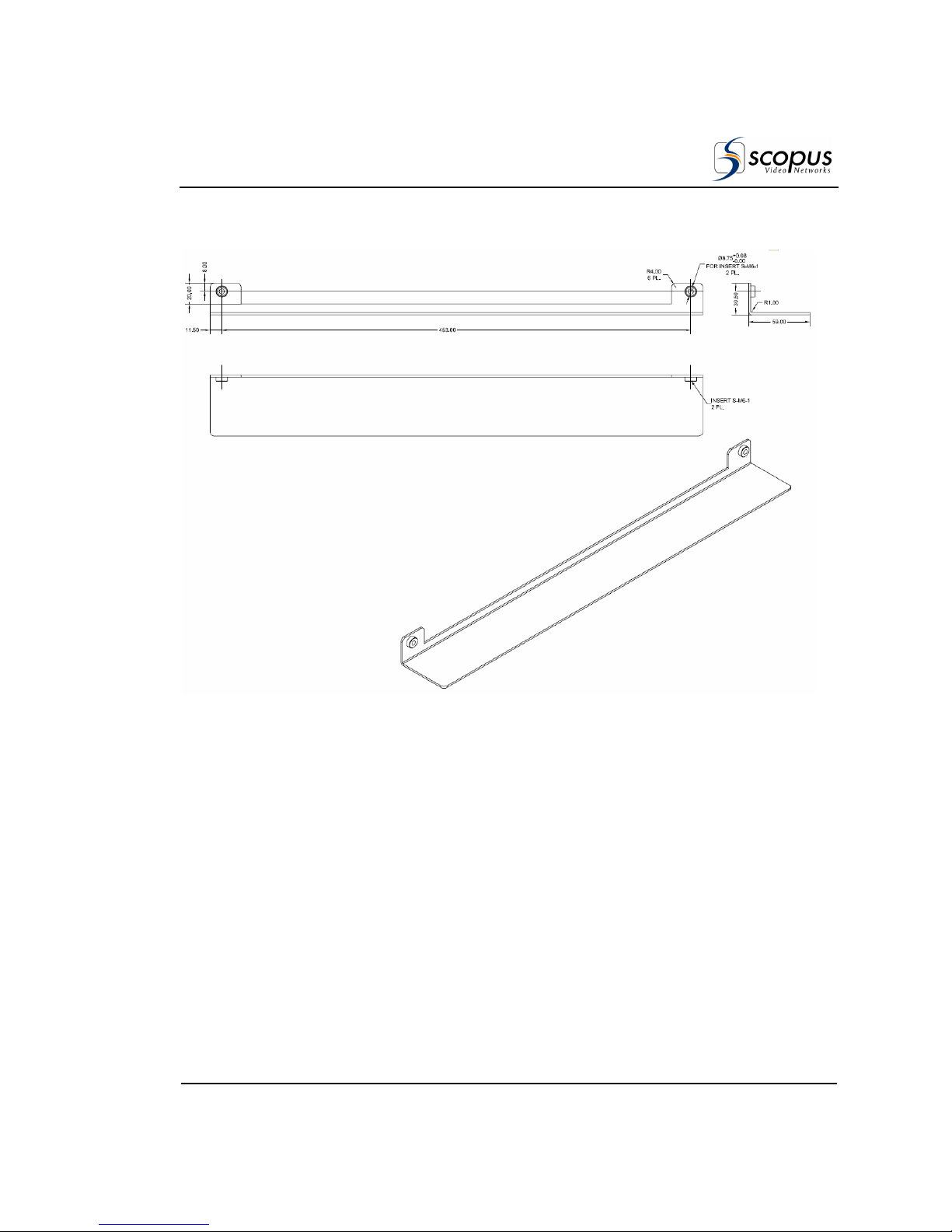
IRD-2900 Series
Professional Integrated Receiver Decoders
Scopus Documents (p/n 100793) Page 2-5
Figure 2-2 illustrates the exact measurements of Scopus’ special rack-slides.
Figure 2-2: Scopus Rack Slide Measurement Specifications
Fasten the pair of rack slides to the rack’s side rails in the device’s designated
location with four M6 screws (two on each side of the rack) before continuing.
After tightly fastening the supporting rack-slides to the rack, perform the
following steps to install the device within the rack:
1. Lay the device on the rack-slides in its designated location within the rack.
Figure 2-3 is a see-through illustration, demonstrating the placing of the
device on the rack-slides.
Page 54
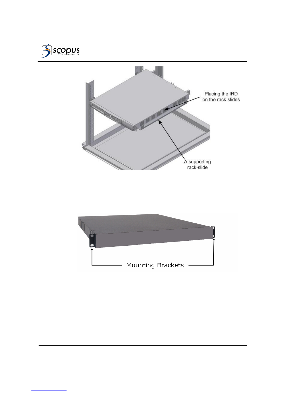
User Manual
Installation
Page 2-6 (Rev. 4.6/ SW v1.80/ December 2007)
Figure 2-3: Laying the Device on the Rack-Slides
2. The device is supplied with two mounting brackets (see Figure 2-4). The
mounting brackets are clipped to the device chassis on both sides before
leaving the factory. Align the mounting brackets’ holes with the relevant
holes in the rack’s side rails.
Figure 2-4: Clipped Mounting Brackets
3. Fasten the mounting brackets to the side-rails with four screws (two on each
side). The device is now safely installed within the rack.
Page 55
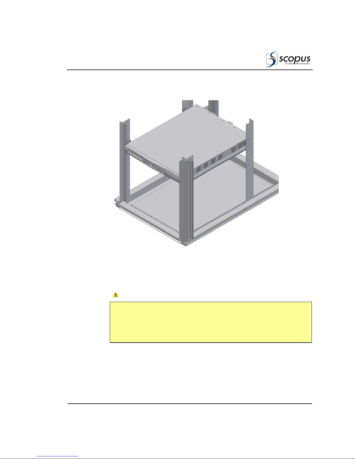
IRD-2900 Series
Professional Integrated Receiver Decoders
Scopus Documents (p/n 100793) Page 2-7
Figure 2-5 illustrates a general view of the device, when installed within the 19’’
rack.
Figure 2-5: Device Mounted on a Pair of Rack-Slides
A single pair of rack-slides can carry up to 50Kg (110 lbs). This allows saving
rack space by placing a number of Scopus rack-mount devices one upon the
other (be careful not to exceed the specified maximum weight).
W
ARNING
DO NOT APPLY OVER 50KG (110LBS) OF WEIGHT ON A SINGLE PAIR OF
RACK-SLIDES. DOING SO MAY RESULT IN COLLAPSING OF THE RACKSLIDES, SERIOUS INJURIES TO PERSONNEL, AND DAMAGE TO
EQUIPMENT.
Page 56
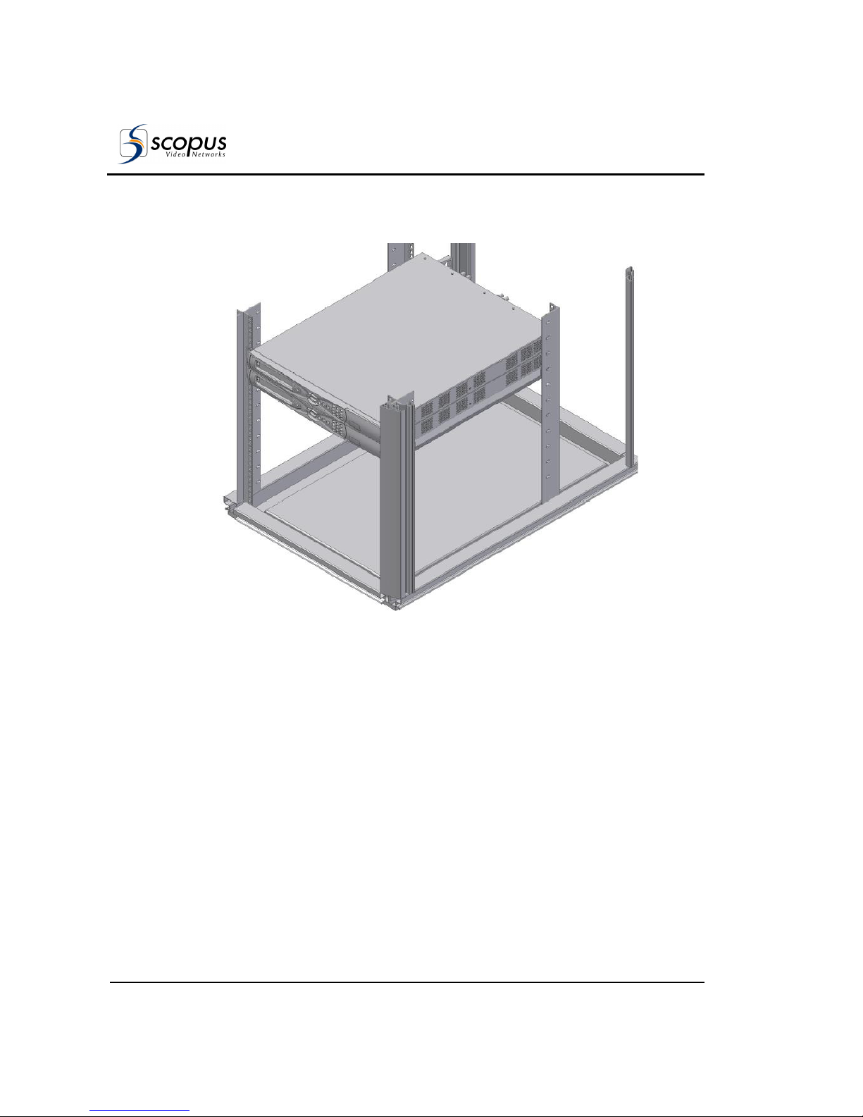
User Manual
Installation
Page 2-8 (Rev. 4.6/ SW v1.80/ December 2007)
Figure 2-6 illustrates multiple devices when rack-mounted on a single pair of
rack-slides.
Figure 2-6: Multiple Devices Mounted on a Single Pair of Rack-Slides
Page 57
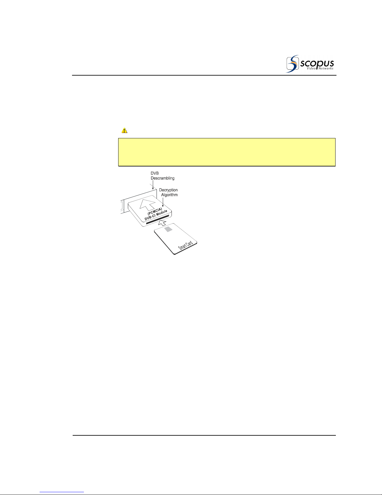
IRD-2900 Series
Professional Integrated Receiver Decoders
Scopus Documents (p/n 100793) Page 2-9
2.3.3. Insertion of the DVB-CI Module
(PCMCIA)
C
AUTION
D
O NOT REMOVE OR INSERT THE
DVB-CI
MODULE OR THE SMART CARD WHILE THE
IRD-2900
IS POWERING UP OR INITIALIZING.
Figure 2-7: DVB-CI Module
Figure 2-7 illustrates the IRD-2900 with the
DVB-CI module (PCMCIA card) and the Smart
Card used to decrypt the incoming signal. The
IRD-2900 is provided with two PCMCIA slots for
up to two DVB-CI modules. The PCMCIA should
be firmly inserted into one of the two provided
slots to ensure contact. Each DVB-CI module
accommodates one Smart Card, inserted with
the UP mark pointing upwards and forward.
When installed, the card is detected
automatically by the IRD-2900 and enabled if the
three following conditions are valid:
• The installed card must be EN50221
compatible
• Services have been selected at TV1/TV2 (for
further information see section 4.2.5.1)
• Using a valid card licensing
Page 58
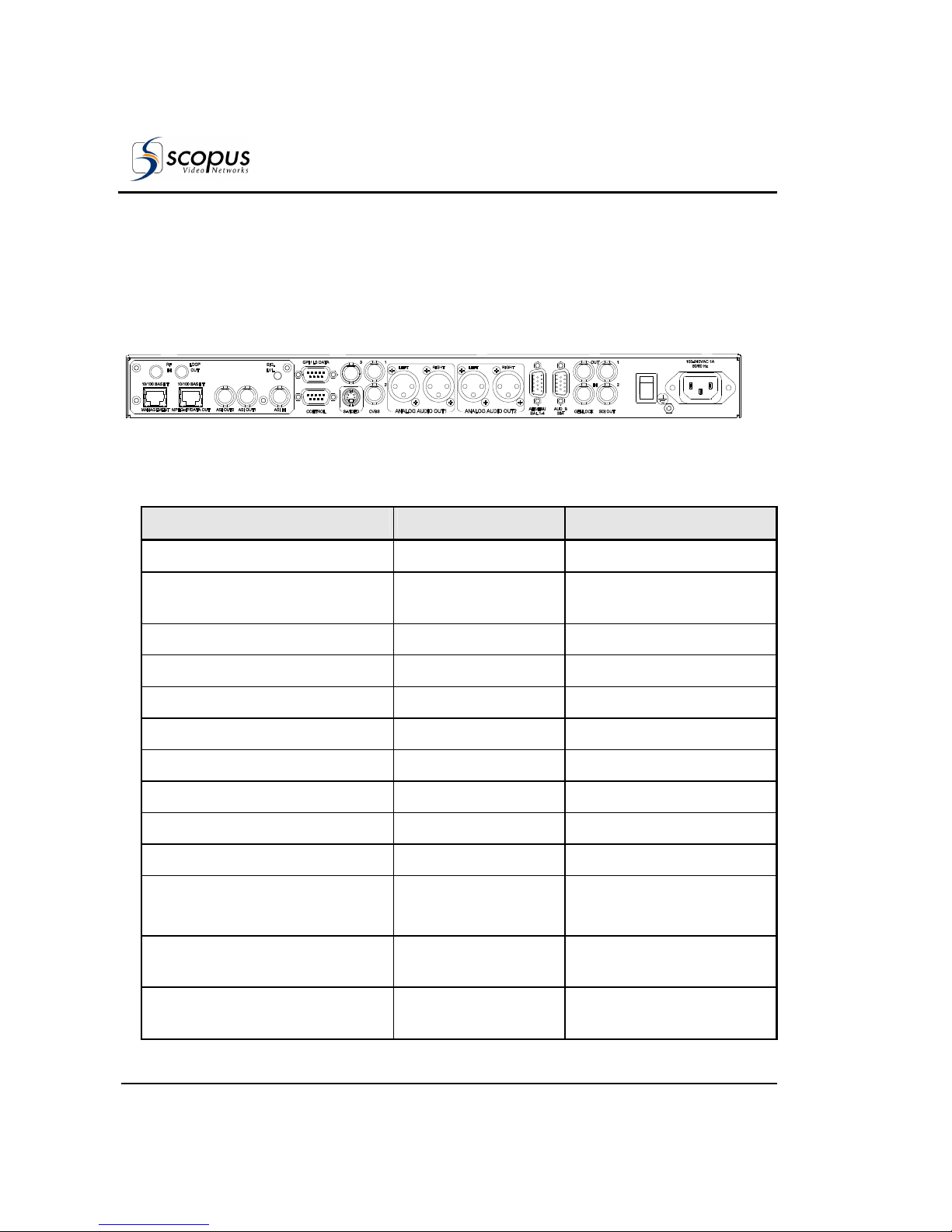
User Manual
Installation
Page 2-10 (Rev. 4.6/ SW v1.80/ December 2007)
2.4. C
ABLE CONNECTION
The IRD-2900 provides all the connections on its rear panel.
The rear panel is comprised of audio outputs, video outputs, data outputs, and
control interfaces (see Table 2-1 for cable connection specifications).
Figure
2-8
illustrates the IRD-2992 rear panel in order show connector types.
Figure 2-8: IRD-2992 Rear Panel
Table 2-1: IRD-2900 Rear Panel – Connectors and Cables
I
NTERFACE
C
ONNECTOR TYPE
C
ABLE TYPE
L-Band Front-end RF IN
75 Ω F-Type
RG-6
L-Band Front-end
Loop-Through Connector
75 Ω F-Type
RG-6
MPEGoIP Input
RJ-45 FTP Cat 5
Management
RJ-45 FTP Cat 5
MPEGoIP/DATA Output
RJ-45 FTP Cat 5
Analog Audio Out1 left
600 Ω XLR (balanced)
Shielded audio cable
Analog Audio Out1 right
600 Ω XLR (balanced)
Shielded audio cable
Analog Audio Out2 left
600 Ω XLR (balanced)
Shielded audio cable
Analog Audio Out2 right
600 Ω XLR (balanced)
Shielded audio cable
Video Out, S-Video Y/C
75 Ω DIN connector
Super video cable
Composite Video Out, CVBS1
75 Ω BNC
RG-59
RG11 A/U (recommended)
Composite Video Out, CVBS2
75 Ω BNC
RG-59
RG11 A/U (recommended)
Composite Video Out, CVBS3
75 Ω BNC
RG-59
RG11 A/U (recommended)
Page 59
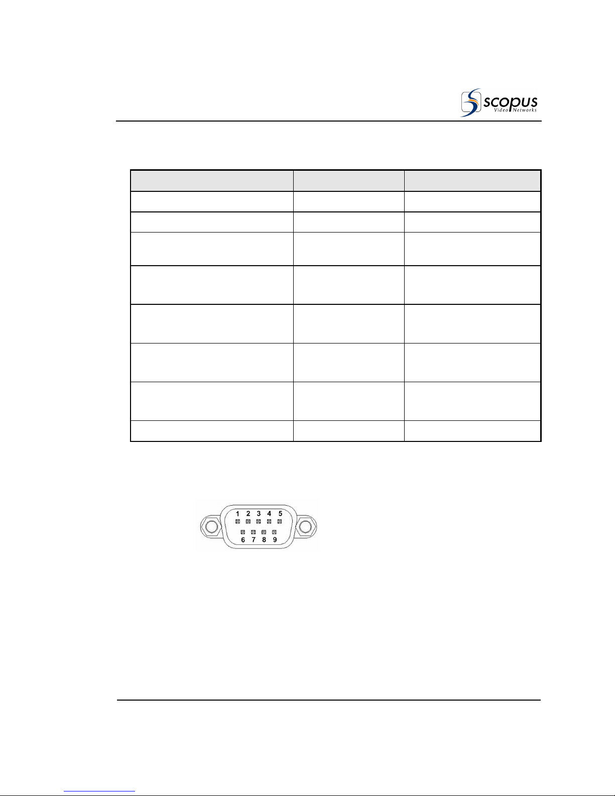
IRD-2900 Series
Professional Integrated Receiver Decoders
Scopus Documents (p/n 100793) Page 2-11
Table 2-1: IRD-2900 Rear Panel – Connectors and Cables
I
NTERFACE
C
ONNECTOR TYPE
C
ABLE TYPE
Data Output (RS-232/RS-422)
9 PIN D-Type Serial Cable
Control (RS-232/RS-485)
9 PIN D-Type Serial Cable
Audio Balanced 3 & 4
600 Ω D-sub 15p to
4XLR
Breakout Cable
204346 (Scopus material)
AES/EBU 1-4 Unbalanced
75 Ω 4xBNC or
75 Ω D-sub 15p
BNC Cable
ASI in/out1/out2
75 Ω BNC
RG-59
RG11 A/U (recommended)
Genlock In
75 Ω BNC
RG-59
RG11 A/U (recommended)
Genlock Out
75 Ω BNC
RG-59
RG11 A/U (recommended)
SDI out 1 &2
75 Ω BNC
RG-59
The IRD-2900 series supports terminal-control from a standard PC through a
serial RS-232/RS-485 connector.
Figure 2-9 illustrates the Control Interface and Low Speed Data/GPI 9-pin male
connectors pin numbering.
Figure 2-9: 9-Pin Male Connector Pin Numbering
Page 60
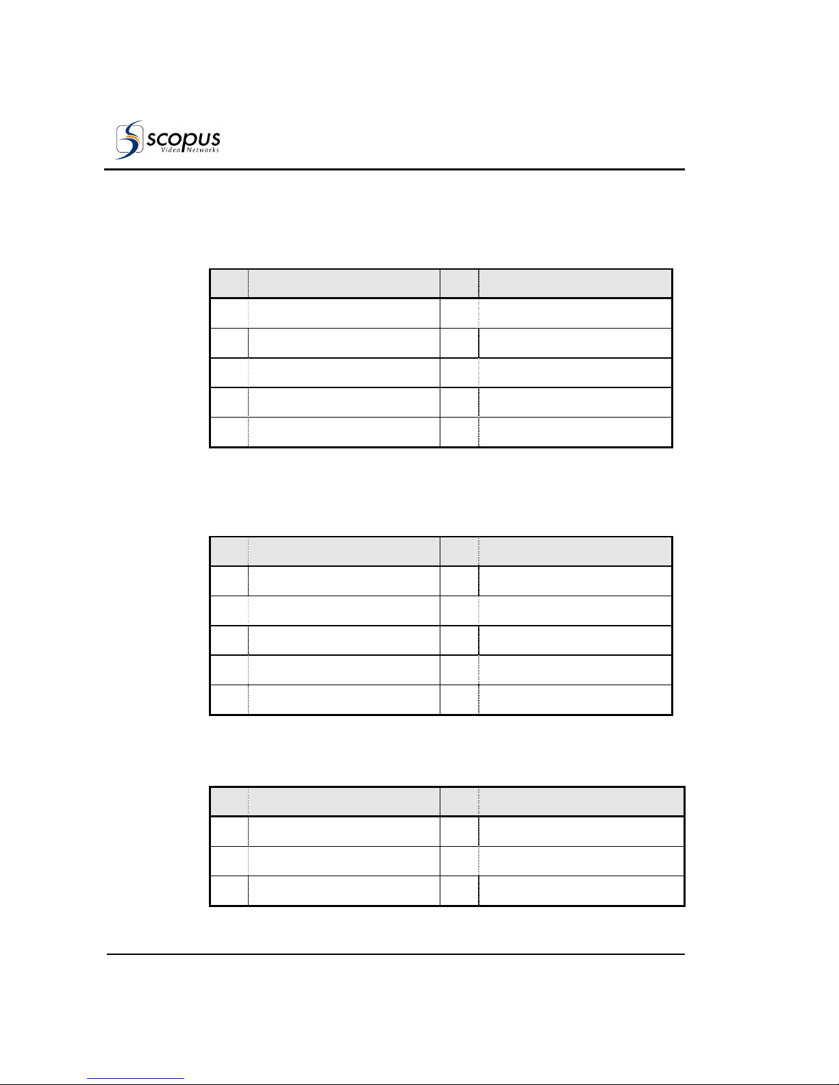
User Manual
Installation
Page 2-12 (Rev. 4.6/ SW v1.80/ December 2007)
Table 2-2 lists the RS-232/RS-485 Control Interface connector pin-out.
Table 2-2: RS-232/RS-485 Control Connector Pin-Out
PIN F
UNCTION
PIN F
UNCTION
1 RS-232 CD/RS-485 TX (+) 6 RS-232 DSR/RS-485 TX (-)
2 RS-232 RxD 7 RS-232 RTS
3 RS-232 TxD 8 RS-232 CTS/RS-485 RX (+)
4 RS-232 DTR 9 RS-232 Ring/RS-485 RX (-)
5 Common
Table 2-3 lists the RS-232 low speed data and GPI interface pin-out. This
connector is used at the same time for both GPI and low-speed data output.
Table 2-3: RS-232 Low Speed Data and GPI Pin-Out
PIN F
UNCTION
PIN F
UNCTION
1 GPI1 NC 6 GPI1 Common
2 RxD 7 GPI1 NO
3 TxD 8 GPI2 NC
4 GPI2 Common 9 GPI2 NO
5 Common
Table 2-4 lists the RS-422 high speed data and interface pin-out.
Table 2-4: RS-422 High Speed Data Pin-Out
PIN F
UNCTION
PIN F
UNCTION
3 Enable (-) 6 Enable (+)
4 Data (-) 7 Clock (-)
5 Data (+) 8 Clock (+)
Page 61
IRD-2900 Series
Professional Integrated Receiver Decoders
Scopus Documents (p/n 100793) Page 2-13
Table 2-5 lists the Audio 3-4 breakout cable interface pin-out.
Table 2-5: Audio 3-4 Breakout Cable Pin-Out (Scopus P/N 204346)
PIN F
UNCTION
PIN F
UNCTION
1 Audio 4 XLR Right (+) 8 Audio 4 XLR Left Common
2 Audio 4 XLR Left (+) 10 Audio 3 XLR Left Common
3 Audio 3 XLR Right Common 11 Audio 4 XLR Right (-)
4 Audio 3 XLR Right (+) 12 Audio 4 XLR Left (-)
5 Audio 3 XLR Left (+) 14 Audio 3 XLR Right (-)
7 Audio 4 XLR Right Common 15 Audio 3 XLR Left (-)
Table 2-6 lists the AES/ABU balanced breakout cable pin-out.
Table 2-6: AES/EBU Balanced Breakout Cable Pin-Out (Scopus P/N
204345)
PIN F
UNCTION
PIN F
UNCTION
1 AES/EBU 4 (+) 8 AES/EBU 3 Common
2 AES/EBU 3 (+) 10 AES/EBU 1 Common
3 AES/EBU 2 Common 11 AES/EBU 4 (-)
4 AES/EBU 2 (+) 12 AES/EBU 3 (-)
AES/EBU 1 (+) 14 AES/EBU 2 (-)
7 AES/EBU 4 Common 15 AES/EBU 1 (-)
Page 62
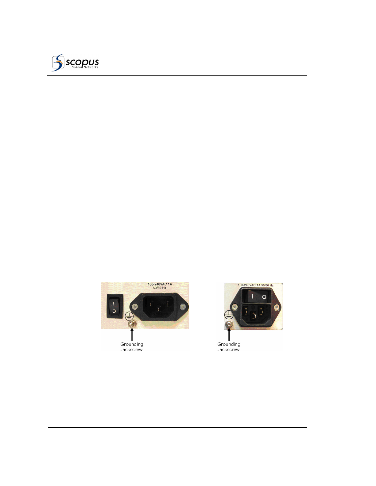
User Manual
Installation
Page 2-14 (Rev. 4.6/ SW v1.80/ December 2007)
2.5. I
NITIALIZATION AND
C
ONFIGURATION
Before powering-up the IRD-2900, ensure that all cabling is correct. Ensure that
the unit is connected to the main power supply and correctly grounded.
2.5.1. Electrical Power Connection
The IRD-2900 is powered by an AC power supply unit or by an optional external
DC power source. The following describes the AC and CD electrical power
connections.
2.5.1.1. AC Power Supply
Grounding of is provided when the AC power cable is connected to the device’s
AC connector. The IRD-2900 is shipped with either AC connector configuration,
as shown in Figure 2-10.
Before powering-up a rack-mounted IRD-2900, the device’s grounding jackscrew
must be connected to the rack housing, which must be correctly grounded (see
Figure 2-10).
AC Power Supply Configuration 1 AC Power Supply Configuration 2
Figure 2-10: Power Supply Configurations and Rack-Mount Grounding Jackscrew
Page 63
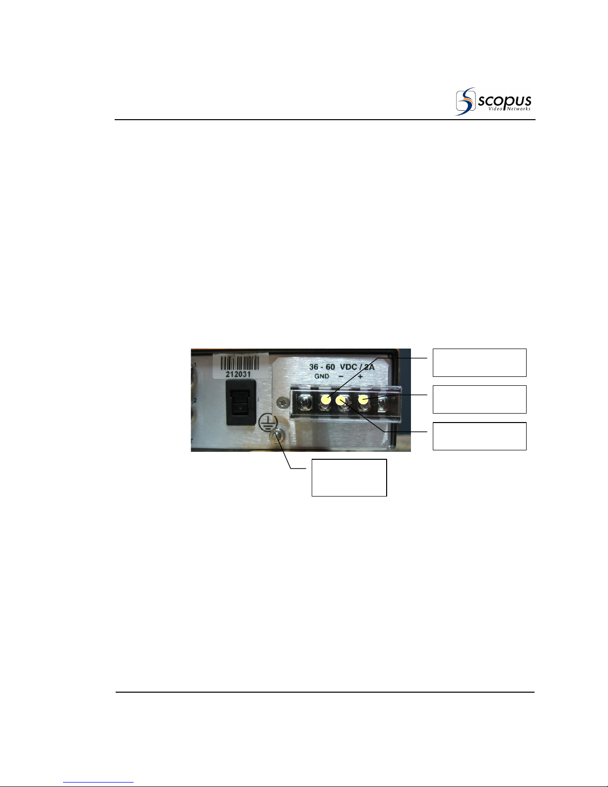
IRD-2900 Series
Professional Integrated Receiver Decoders
Scopus Documents (p/n 100793) Page 2-15
2.5.1.2. DC Power Supply
DC power supply is an optional feature of the IRD-2900. If the unit is fitted with
a -48V CD power supply, connect the external 48V DC source by performing the
following (refer to Figure 2-11):
1. Connect a (+) 48V DC source wire to the (+) contact on the power terminal
board.
2. Connect a (-) 48V DC source wire to the (-) contact on the power terminal
board.
3. Connect Grounding point wire to the (GND) contact on the power terminal
board.
When the IRD is rack-mounted, the jackscrew (see Figure 2-11) must be
connected to the rack housing, which in turn should be properly grounded.
Figure 2-11: DC Power Supply and Rack-Mount Grounding Jackscrew
Grounding
Jackscrew
+
Contact
-
Contact
GND Contact
Page 64

User Manual
Installation
Page 2-16 (Rev. 4.6/ SW v1.80/ December 2007)
2.5.2. Powering Up
When powering up the IRD-2900 and the receiver is not tuned, expect one of
the following warnings:
• Front-End warning – Demodulator not sync
• Bit Stream warning – No sync – 0x47 detected
• Bit Stream warning – PSI not detected
In case the IRD-2900 warning LED is lit orange, the operator must perform the
following:
• Tune or configure the IRD-2900 device
• Select a service from the input stream
When the IRD-2900 is correctly configured, “All OK” is displayed and both LEDs
are lit green.
N
OTE
Prior to initialization, review Chapter 4-Operation and Management, for how to
use and navigate through the menus and for information on configuration
parameters.
2.5.3. Tuning
The IRD-2900 receiver must be configured to receive a transport stream. For
details about an IRD-2900 device with a DVB-S receiver module, see Section
4.2.2. For details about an IRD-2900 device with an MPEG-over-IP front-end
module, see Section 4.2.2.4.
Page 65

IRD-2900 Series
Professional Integrated Receiver Decoders
Scopus Documents (p/n 100793) Page 2-17
2.5.4. Performing Serviceability Check
After installing, initializing, or configuring the IRD, maintenance checks must be
performed to ensure that the unit is serviceable. A video monitor must be
connected to the IRD-2900 to perform the check lists systematic instructions for
performing a serviceability check.
Table 2-7: IRD-2900 Serviceability Check
S
TEP
C
HECK
1 On the LCD display, the LCD status message reads "STATUS OK".
2 On the IRD-2900 front panel the two LEDs are lit green.
3 The service selected is displayed on the LCD display.
4 Video picture is displayed on monitor.
5 Audio channels left and right.
Page 66

Page 67
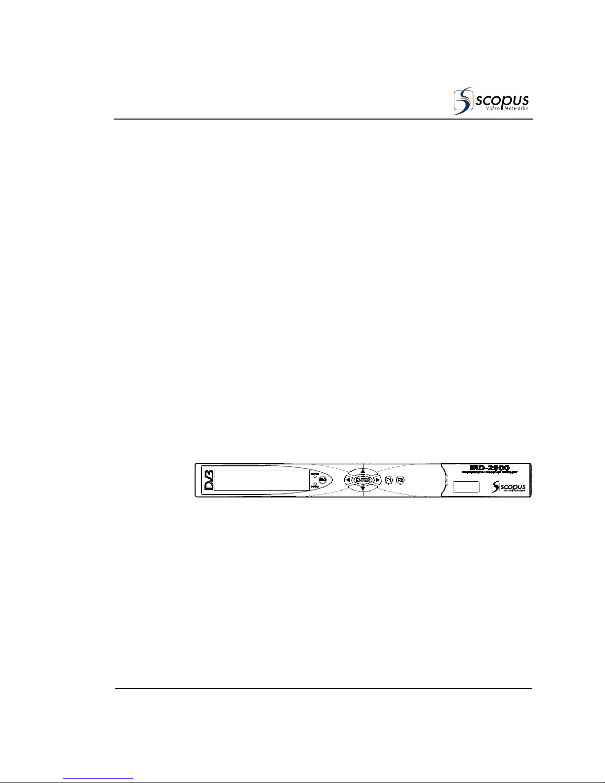
IRD-2900 Series
Professional Integrated Receiver Decoders
Scopus Documents (p/n 100793) Page 3-1
Chapter 3.
IRD-2900 C
ONTROL INTERFACES
This section explains the Front Panel and Web Management control interfaces
used for operating, configuring, and monitoring the IRD-2900.
3.1. F
RONT PANEL CONTROL
I
NTERFACE
The front panel control interface explained in this section is composed of the
following:
• Controls and Displays – see section 3.1.1
• Front Panel Screens – see section 3.1.2
• Menu Tree – see section 3.1.3
• Front Panel Initialization Sequence – see section 3.1.4
3.1.1. Controls and Displays
The front panel is used for extensive local control and for monitoring the device’s
operation. Figure 3-1 illustrates the IRD-2900 front panel.
Figure 3-1: Front Panel
The IRD-2900 front panel contains:
• LCD Display
The LCD display is a large, easy to use, graphical display. It is used to display
enhanced menus with graphical interfaces, such as: charts, radio buttons, tables,
and icons.
Page 68

User Manual
IRD-2900 Control Interfaces
Page 3-2 (Rev. 4.6/ SW v1.80/ December 2007)
• Status LEDs
The two LEDs indicate WARNING and PWR/FAIL statuses, when both LEDs
are lit green the IRD-2900 status is OK. The WARNING LED (Green/Orange)
indicates the operational status. The PWR/FAIL LED (Green/Red) indicates
the hardware status.
• Arrow Keys
The arrow keys include [Up], [Down], [Right], [Left]. The keys are used to
navigate between the different menu items and sub-menus. They are also
used to select and change parameters during setup and configuration
procedures.
• [Enter] Key
The Enter key is used for selecting or entering a configuration setup.
• [Esc] Key
The ESC key is used to abort a configuration setup or to return to the
menu's previous level.
• Programmable Keys
The [F1] and [F2] buttons allows quick access to specific front-panel menu
screen. Each programmable key can store one menu screen path.
To create a quick access shortcut:
1. Go to the wanted front-panel menu screen. Use the keypad to navigate.
2. Press and hold the [F1] key or the [F2] key, when press [Esc].
3. Press [ENTER] (while holding the [F1] key or the [F2] key).
4. Release the [ENTER] key.
5. Release the [F1] key or [F2] key.
Page 69
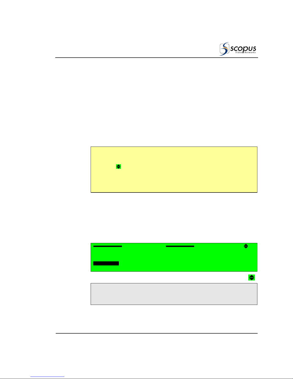
IRD-2900 Series
Professional Integrated Receiver Decoders
Scopus Documents (p/n 100793) Page 3-3
3.1.2. IRD-2900 Front Panel Screen
Types
The IRD-2900 display leads to the following five screen types:
• Menu Navigation screen
• Edit Menu screen
• Table Menu screen
• Edit Value screen
• Select Value screen
N
OTE
The Front panel can display only up to four menu items at a time. When a menu
has more than four items, the first four are visible in the panel, followed by a
scroll icon [ ]. Additional items can be accessed using the [up]/[down]
arrows. To illustrate the difference between the two types of items, two types of
screen shots were used in this user manual: dark grey for the visible items and
light grey for the hidden ones.
Sections 3.1.2.1 to 3.1.2.5 detail the different front panel screen types.
3.1.2.1. Menu Navigation Screen
The Menu Navigation screen enables navigating through the tree structure of
the IRD-2900 menu.
In this example, the menu navigation screen displays the following items:
Configuration
Configuration Configuration
Configuration
1111----2222
1
1 1
1
Receiver
ReceiverReceiver
Receiver
2222
Stream
Stream Stream
Stream
3333
Service
Service Service
Service
4444
Video
Video Video
Video
5555
Audio
Audio Audio
Audio
6666
Data
Data Data
Data
7777
Conditional Access
Conditional Access Conditional Access
Conditional Access
Unit
Unit Unit
Unit
Page 70
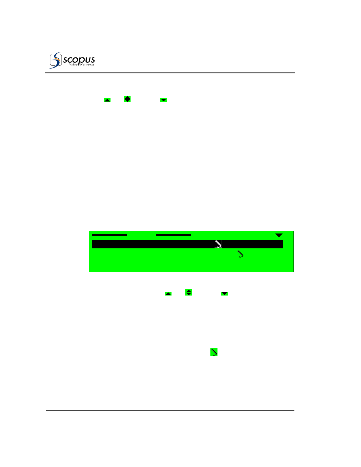
User Manual
IRD-2900 Control Interfaces
Page 3-4 (Rev. 4.6/ SW v1.80/ December 2007)
A. Top line indicates the menu name (Configuration) and the menu hierarchal
position (
1111----2222
, for example
Configuration
ConfigurationConfiguration
Configuration
under the
Root
RootRoot
Root
menu).
[ Up]/[ Up/Down]/[ Down] symbols indicate that up or down scrolling
is enabled.
B. Next up to four displayed lines is a list of numbered items.
C. Additional Available Items
The list can include more than four items, but only four items are visible at a
time. When more than four items are enabled, you can scroll using the
[UP]/[Down] arrow keys.
The currently selected option is displayed with white characters over a black
background (see Item #3 in the example above).
To access the next menu level press [Enter] to select the marked item
(either another menu navigation screen or an Edit Menu screen).
3.1.2.2. Edit Menu Screen
The Edit menu screen enables selecting, changing or displaying the value of a
parameter or set of parameters.
In this example, the Edit Menu screen displays the following items:
Stream
Stream Stream
Stream
1111----2222----2222
1111
Decoder Stream Source
Decoder Stream Source Decoder Stream Source
Decoder Stream Source FRONT
FRONT FRONT
FRONT----END (QPSK)
END (QPSK)END (QPSK)
END (QPSK)
2222
27MHz Synchronization
27MHz Synchronization 27MHz Synchronization
27MHz Synchronization STREAM PCR
STREAM PCR STREAM PCR
STREAM PCR
A. Top line indicates the menu name (
Stream
StreamStream
Stream
) and the menu hierarchal
position (
1111----2222----2222,
for example
Root
RootRoot
Root----Configuration
ConfigurationConfiguration
Configuration----Stream
StreamStream
Stream
) in the
IRD-2900 Menu Tree. [ Up]/[ Up/Down]/[ Down] symbols indicate
that up or down scrolling is enabled.
B. Next up to four displayed lines is a list of numbered items relevant to the
menu and their current values. The information provided for each list item
is:
• Left-aligned column displays a numbered list of parameters.
• Right-aligned column displays parameter values.
- Editable parameters have a pencil icon next to them.
- Parameters without the pencil icon are for information only.
Page 71

IRD-2900 Series
Professional Integrated Receiver Decoders
Scopus Documents (p/n 100793) Page 3-5
C. Additional Available Items
The list can include more than four items, but only four items are visible at the
time. When more than four items are enabled, you can scroll the list using the
[UP]/[Down] arrow keys.
The currently selected option is displayed with white characters over a black
background (see Item #1 in the example above).
Press [ESC] to abort the selection or to return to the menu’s previous level.
Press [Enter] to select the pointed editable option; a parameter-editing
screen is displayed. This can be a Table Menu screen, an Edit Value screen, or a
Select Value screen.
3.1.2.3. Table Menu Screen
The Table menu screen displays parameter information, using a table format.
In this example, the Table Menu screen displays the following columns:
Name
NameName
Name ID
IDID
ID Type
TypeType
Type Mode
ModeMode
Mode
1111
PROGRAM 1
PROGRAM 1 PROGRAM 1
PROGRAM 1 000A
000A000A
000A TV
TVTV
TV FTA
FTAFTA
FTA
2222
PROGRAM 2
PROGRAM 2 PROGRAM 2
PROGRAM 2 0046
00460046
0046 TV
TVTV
TV FTA
FTAFTA
FTA
3333
PROGRAM 3
PROGRAM 3 PROGRAM 3
PROGRAM 3 0050
00500050
0050 TV
TVTV
TV CAS
CASCAS
CAS
4444 PROGRAM 4
PROGRAM 4 PROGRAM 4
PROGRAM 4 01F7
01F7 01F7
01F7 TV
TVTV
TV CAS
CASCAS
CAS
A. Top line displays the headers for each table column.
B. Next up to four displayed lines is a numbered list of parameters relevant
to the menu and their current values. A radio button indicates which
parameter is currently active (
is currently enabled and
is currently
disabled)
C. Additional Available Items
The list can include more than four items, but only four items are visible at a
time. When more than four items are available, you can scroll the list using
the [UP]/[Down] arrow keys.
The currently selected option is displayed with white characters over a black
background (see Item #2 in the example above).
Press [ESC] to abort the selection and return to the Edit Menu screen
without changing the parameters.
Press [Enter] to select the currently enabled button
.
The selected option
becomes enabled and the former active option is disabled.
Page 72
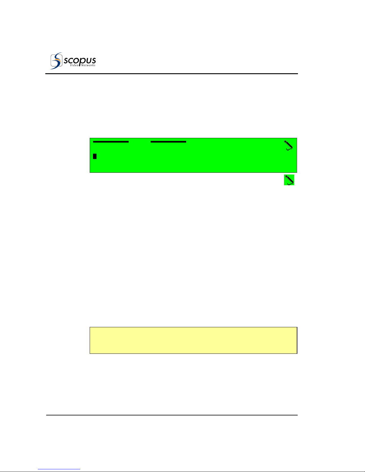
User Manual
IRD-2900 Control Interfaces
Page 3-6 (Rev. 4.6/ SW v1.80/ December 2007)
3.1.2.4. Edit Value Screen
The Edit Value screen enables setting a parameter value. The parameter value
can be a number or a string of characters. Each digit or character is set up
individually.
In this example, the Edit Value screen displays the following information:
Pcr1
Pcr1 Pcr1
Pcr1
1111062 [Hex]
062 [Hex]062 [Hex]
062 [Hex]
<0000
<0000 <0000
<0000 –––– 1FFF>
1FFF> 1FFF>
1FFF>
A. Top line displays the parameter name (
Pcr1
Pcr1Pcr1
Pcr1
). The pencil icon
indicates that the parameter value is editable.
B. Second line displays the current parameter value. Change the value of the
parameter with the arrow keys:
• [Left] and [Right] arrow keys are used to mark a digit or a character
for change. The marked digit or a character is displayed with white
character over black background (see example in page 3-5)
• [Up] and [Down] arrow keys are used to scroll up or down the digits (0
through 9) or the characters (a to z, A to Z, 0 to 9 and so on.). The scroll
range can be limited to prevent values being out of range.
C. Third line displays the allowed range of parameter values.
Press [ESC] to abort the setup and return one level up to the Edit Value
Screen without changing the parameters.
Press [Enter] to accept the value. The display returns one level up to the
Edit Value Screen and the new value is displayed as the current parameter
value.
N
OTE
When entering an wrong or out-of-range value the display dismisses the last
change and returns one level up in the menu tree.
Page 73

IRD-2900 Series
Professional Integrated Receiver Decoders
Scopus Documents (p/n 100793) Page 3-7
3.1.2.5. Select Value Screen (Multiple Choices)
The Select Value screen displays a list of selectable items.
In this example, the Select Value screen displays the following information:
Format
Format Format
Format
3333
PAL M
PAL M PAL M
PAL M
4444
PAL BG
PAL BG PAL BG
PAL BG
5555
PAL D
PAL D PAL D
PAL D
6666
PAL N
PAL N PAL N
PAL N
A. Top line displays the parameter name (
Format
FormatFormat
Format
). The pencil icon indicates
that the items are selectable from the list of displayed options.
[ Up]/[ Up/Down]/[ Down] symbols indicate that up or down scrolling
is enabled.
B. Next up to four displayed lines is a numbered list of parameters relevant
to the menu and their current values. A radio button indicates which
parameters are currently activated (
is
currently enabled and
is
currently disabled)
C. Additional Available Items
The list can include more than four items, but only four items are visible at a
time. When more than four items exist, you can scroll the list using the
[UP]/[Down] arrow keys.
The currently selected option is displayed with white characters over a black
background (see Item #4 in the example above).
Press [ESC] to abort setup and return one level up to the Select Value Screen
without changing the parameters.
Press [Enter] to select the marked option (the selected option is enabled
and
the former enabled option is disabled
). The display returns up one level to the
Select Value screen; the new option is displayed as the current parameter
option.
Page 74
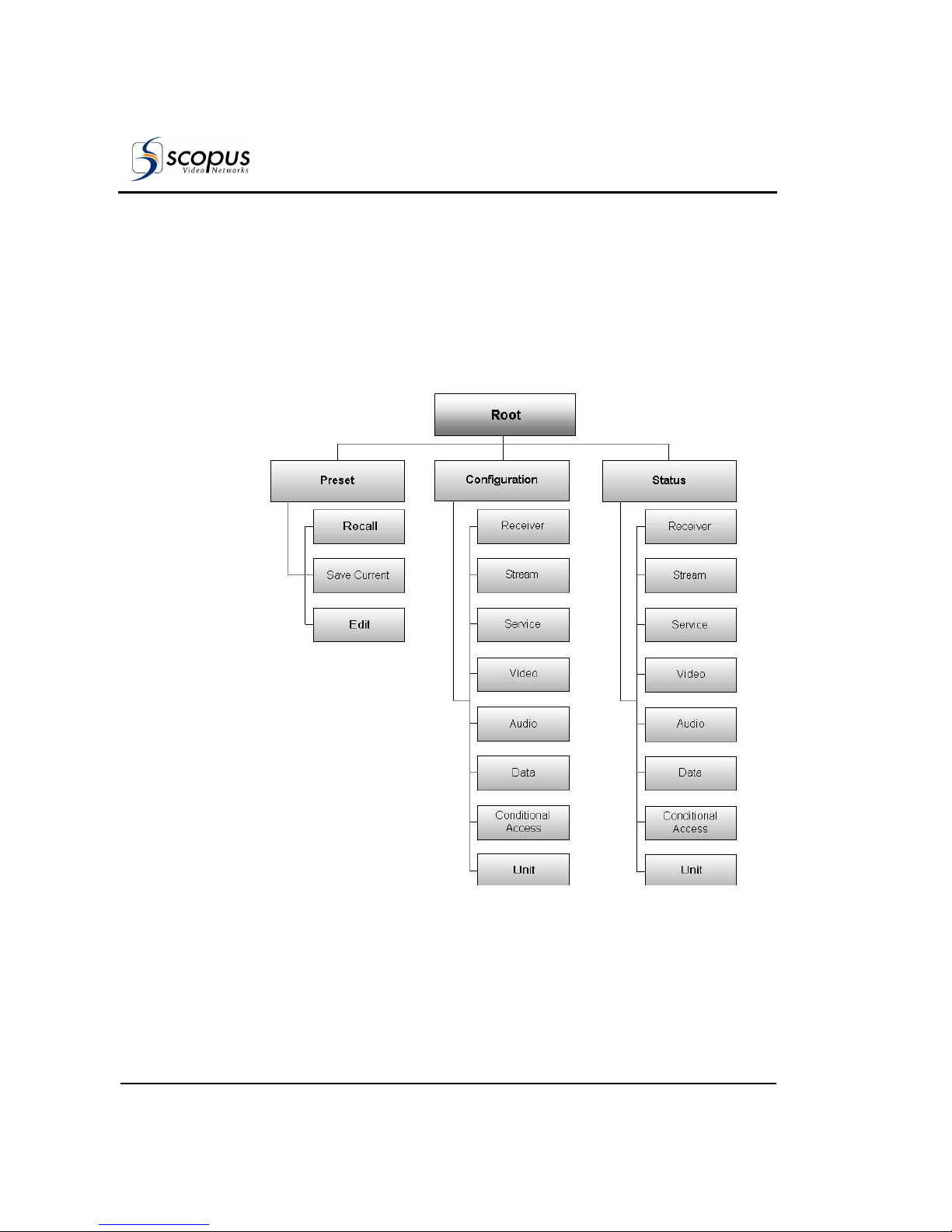
User Manual
IRD-2900 Control Interfaces
Page 3-8 (Rev. 4.6/ SW v1.80/ December 2007)
3.1.3. IRD-2900 Menu Tree
Setup, control, and monitoring of the IRD-2900 operation can be performed
locally by using the IRD-2900 Menu.
This menu is displayed on the front panel LCD display and is operated using the
front panel control keys. The basic tree structure of the IRD-2900 front panel
menu is illustrated in Figure 3-2.
Figure 3-2: IRD-2900 Front Panel Menu (Root Menu) - Basic Structure
Page 75
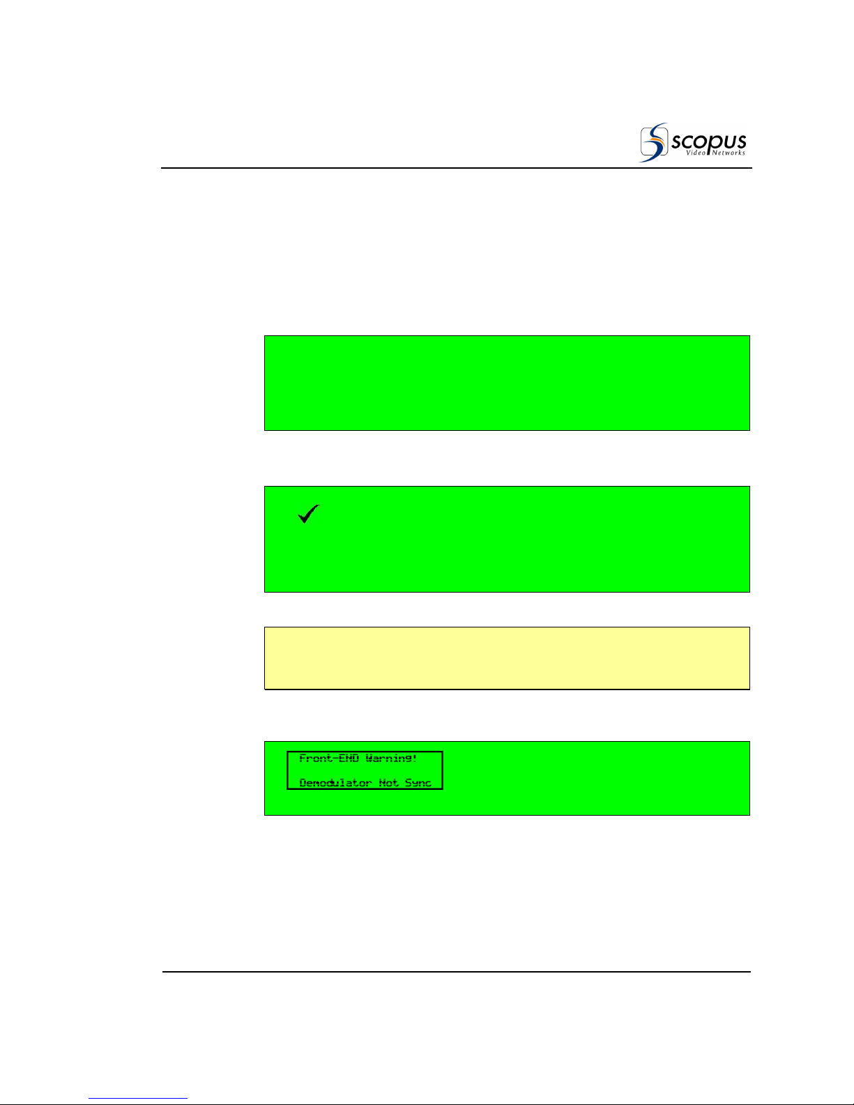
IRD-2900 Series
Professional Integrated Receiver Decoders
Scopus Documents (p/n 100793) Page 3-9
3.1.4. Front Panel Initialization
Sequence
To activate the IRD-2900 Front Panel Root Menu perform the following:
1. Power up the IRD-2900. The IRD-2900 initialization phase begins and the
initialization message is displayed.
MPEG
MPEG MPEG
MPEG----2 I.R.
2 I.R.2 I.R.
2 I.R. Service1:
Service1:Service1:
Service1:
Initializing
InitializingInitializing
Initializing
Please Wait...
Please Wait...Please Wait...
Please Wait...
2. When initialization complete, the IRD-2900 displays one of two options:
• Status OK – Both LEDs are lit green.
Status OK
Status OKStatus OK
Status OK Service1: TV
Service1: TVService1: TV
Service1: TV
Click Enter for menu
Click Enter for menu Click Enter for menu
Click Enter for menu TRT
TRT TRT
TRT INT
INTINT
INT
N
OTE
Blank Service1 and/or Service2 fields at the front panel' root screen, means
service not chosen. In order to select services see section 4.2.5.1
• Front-End Warning – The warning LED turns orange (For details see
Appendix E).
____________________ ______________________ _
____________________ ______________________ _____________________ ______________________ _
____________________ ______________________ _
Service1:
Service1:Service1:
Service1:
Click Enter for menu
Click Enter for menu Click Enter for menu
Click Enter for menu
____________________ ______________________ _
____________________ ______________________ _____________________ ______________________ _
____________________ ______________________ _
Page 76

User Manual
IRD-2900 Control Interfaces
Page 3-10 (Rev. 4.6/ SW v1.80/ December 2007)
3. Click [Enter] to activate and enter the IRD-2900 Root Menu:
Root
Root Root
Root
1111
1111
Preset
Preset Preset
Preset
2222
Configuration
Configuration Configuration
Configuration
3333
Status
Status Status
Status
The Root Menu provides the following main branch options:
• IRD-2900 Preset Menu – See Section 4.1 for details.
• IRD-2900 Configuration Menu – See Section 4.2 for a detailed
description.
• IRD-2900 Status Menu – See Section 4.3 for details.
Page 77
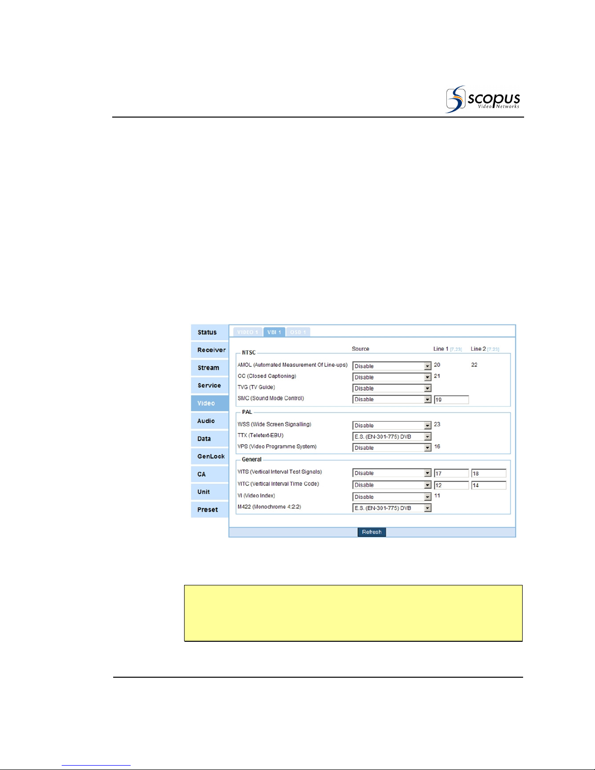
IRD-2900 Series
Professional Integrated Receiver Decoders
Scopus Documents (p/n 100793) Page 3-11
3.2. W
EB
-B
ASED MANAGEMENT
I
NTERFACE
The IRD-2900’s Web-Based Management software is a user-friendly graphical
interface that allows easy control and configuration of the device as well as
monitoring the devices current condition. All this is performed through a remote
computer, using a regular web browser. No additional software is needed.
Managing the IRD-2900 using the Web-based management GUI is as easy as
point-and-click.
The Web-Management interface is used for remotely controlling, configuring,
and monitoring the device, using a standard PC and any standard web browser
(see Figure 3-3 for general view example).
Figure 3-3: Web-Based Management Window – General View
N
OTE
The web-based management is best viewed by Internet Explorer 6.0. Scopus
cannot guarantee viewing quality in older IE versions or other web-browsers,
such as FireFox, Opera, and so on.
Page 78
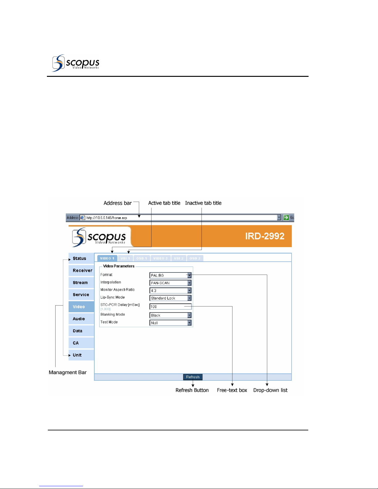
User Manual
IRD-2900 Control Interfaces
Page 3-12 (Rev. 4.6/ SW v1.80/ December 2007)
The section is divided into the following groups:
• Control and Displays – Details the web-management screen sections and
their control elements (see Section 3.2.1)
• Initializing the Web-Based Management – Details the initialization
procedure of the Web- management control interface (see Section 3.2.2)
3.2.1. Controls and Displays
The web-based management is divided into menus and submenus. Each menu's
sub-menu displays (in an explorer window) a list of parameters related to the
menu. In case of any additional parameters, such as advanced configuration
parameters, another parameter-section is displays in the explorer window (see
example in Figure 3-4.
Figure 3-4: IRD-2900 Web-Based Management Interface Screen (Example)
Page 79

IRD-2900 Series
Professional Integrated Receiver Decoders
Scopus Documents (p/n 100793) Page 3-13
The following sections detail the different web-management display objects.
3.2.1.1. Display Elements
The web-based management is divided into display sections for an easy
orientation and to offer a user-friendly control interface. The following
paragraphs detail the different sections:
1. T
ITLE
A static title to the web-based management, displays the Scopus logo and the
device's type (IRD-2900, see Figure 3-5).
Figure 3-5: Web-Based Management Title
2. M
ENU AND SUB-MENU TABS
The tabs surround the explorer window section (see the following paragraph).
The menu tabs are displayed at all times. The sub-menu tabs are dynamic, and
change according to the selected menu (for more information, see Section
3.2.1.2. See tabs example in Figure 3-6).
Page 80
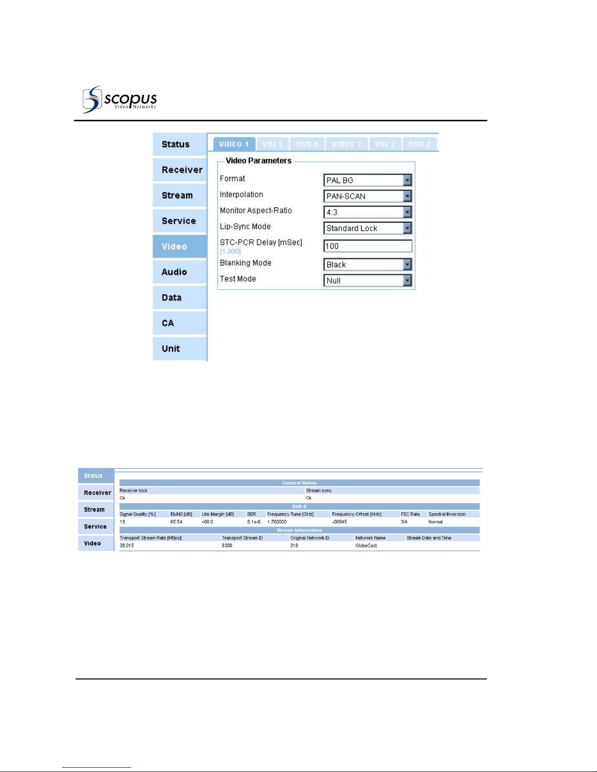
User Manual
IRD-2900 Control Interfaces
Page 3-14 (Rev. 4.6/ SW v1.80/ December 2007)
Figure 3-6: Web-Based Management Menu and Sub-Menu Tabs
3. S
TATUS MENU
The Status menu, located under the 'Status' tab, displays a read-only table.
The table details information regarding the various services encoded by the unit
(see Figure 3-7. For detailed information about the Status menu, see Section
4.3).
Figure 3-7: Status Menu
Page 81
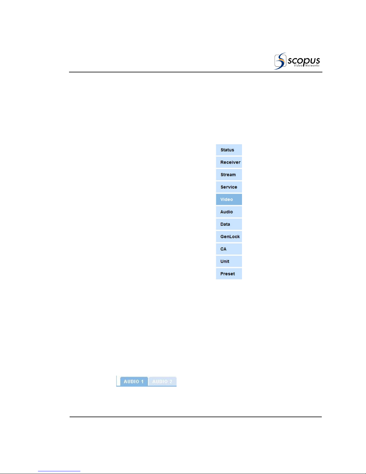
IRD-2900 Series
Professional Integrated Receiver Decoders
Scopus Documents (p/n 100793) Page 3-15
3.2.1.2. Control Elements
The different display sections use different control elements to navigate, view,
and manage the IRD-2900 configuration. The following paragraphs detail these
sections.
1. M
AIN MENU TABS
The main-menu tabs are light-blue
tabs that allow the user to select
one of the main menus in the
encoder (such as video, audio, unit,
and so on).
The main-menu tabs are listed at
the left-side of the explorer-window
section. A selected main-menu tab
changes its color from light-blue to
darker blue (see Figure 3-8).
Figure 3-8: Main-
Menu Tabs
2. S
UB MENU TABS
The sub-menu tabs are light-blue tabs that allow the user to select one of the
specific sub-menus available in the selected menu.
For example, 'Audio' main menu holds the 'Audio 1' and 'Audio 2' tabs,
allowing the user to select Audio 1 or Audio 2 configuration menus.
The sub-menu tabs are aligned above the explorer-window section. A selected
sub-menu tab changes its color from light-blue to darker-blue (see Figure 3-9).
Figure 3-9: Sub-Menu Tabs
Page 82
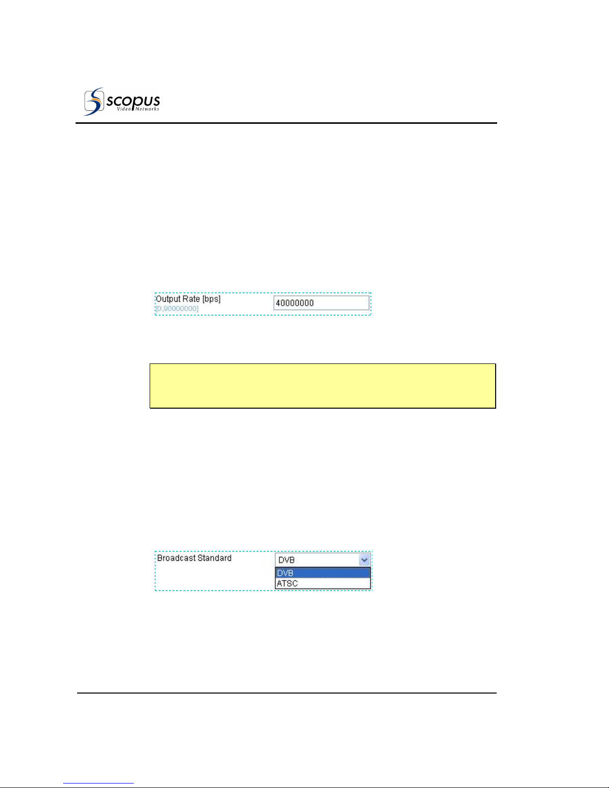
User Manual
IRD-2900 Control Interfaces
Page 3-16 (Rev. 4.6/ SW v1.80/ December 2007)
3. E
DIT VALUE PARAMETER
The parameters-sections in the explorer window display lists of editable
parameters, available for user-configuration. The edit-value parameters provides
a free-text field for the user to type the required value (from within a given
range).
The edit-value parameter is divided into two sections:
• Left Side - Displays the parameter's name. Measure units are specified
within brackets ([]) and the available range is specified in light-blue.
• Right Side - A free-text field. To edit the text, the user must click the field
once, for the cursor to appear. Once the cursor is displayed the user can
type the requested value.
Figure 3-10: Edit-Value Parameter
N
OTE
In order for the new value to take affect the user must type [Enter] after
inserting the new value.
4. S
ELECT VALUE PARAMETER
The parameters-sections in the explorer window display lists of editable
parameters, available for user-configuration. The select-value parameters
display a drop-down list of available values.
The select-value parameter is divided into two sections:
• Left Side - Displays the parameter's name.
• Right Side – A select-value field displaying the currently-selected value.
Clicking the downward-arrow at the right-end of the field displays the
drop-down list of all available values.
Figure 3-11: Select-Value Parameter
5. R
EFRESH BUTTON
Page 83

IRD-2900 Series
Professional Integrated Receiver Decoders
Scopus Documents (p/n 100793) Page 3-17
The 'Refresh' button is located at the bottom of each screen and available at all
times. Clicking this button refreshes the web-page. This is useful for updating
changes that were configured in the front-panel.
Figure 3-12: Refresh Button
3.2.2. Initializing the Web-Based
Management
Setting the management connection through the front panel involves the
following procedures:
• Set the IP Address
• Set the Subnet Mask
• Set the Default Gateway
N
OTE
In order to avoid any errors and faults, Scopus recommends all Ethernet
configurations to be preformed through the front-panel or the RS323 only
A. To set the IP Address:
1. Access the IP Address edit screen. To access the screen, from the Root
menu select ConfigurationUnitEthernet Management portIP
Address.
2. Enter a valid IP Address.
3. Verify that the entered IP address is not allocated to any other device.
B. To set the Subnet Mask:
1. Access the Subnet Mask edit screen. To access the screen, from the Root
menu select ConfigurationUnitEthernet Management portSubnet
Mask.
2. Enter a valid subnet mask.
C. To set the Default Gateway:
1. Access the Default Gateway edit screen. To access the screen, from the Root
menu select ConfigurationUnitEthernet Management portDefault
Gateway
2. Enter a valid Default Gateway.
Page 84

User Manual
IRD-2900 Control Interfaces
Page 3-18 (Rev. 4.6/ SW v1.80/ December 2007)
3. Verify that the IP Address (set in the procedure A) is correlated with the
Default Gateway address.
3.2.2.1. Accessing the Web-Management
Once the IP definitions are set according to the network, the user can access the
web-based management interface. To access the web-management, perform the
following:
1. Launch the web browser.
N
OTE
The web-based management is supported and can be operated through most
web browsers. However, Scopus recommends Internet Explorer 5.0 and higher
for optimal operation.
2. Enter the IRD-2900 IP Address in the Address field, in the following format:
http://xxx.xxx.xxx.xxx (where xxx.xxx.xxx.xxx is the IP address of the
Management port). Once the web-management is displayed, the address
changes to http://xxx.xxx.xxx.xxx/home.asp. See the example in Figure
3-13:
Figure 3-13: IP Address Field
To access the web-based management, user-name and password must be
entered. The default values are:
• User name – ird
• Password – ird
Enter your user name and password in the access box. Press Submit to confirm
or Clear to start over. For password change see section 4.2.11.2
Figure 3-14 displays the Web Management access box.
Page 85
IRD-2900 Series
Professional Integrated Receiver Decoders
Scopus Documents (p/n 100793) Page 3-19
Figure 3-14: IRD-2900 Web Management Access Box
Once the initialization is complete and the web-management is displayed, the
user can set up the system. For details on the web-management operation, see
Chapter 4.
Page 86

Page 87
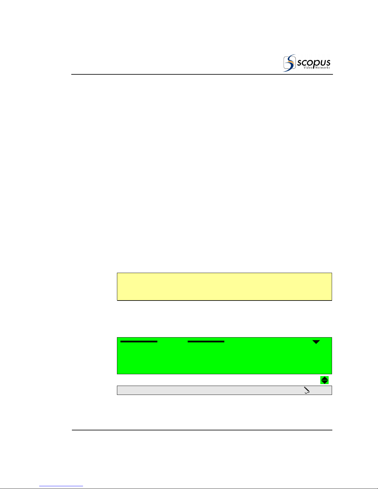
IRD-2900 Series
Professional Integrated Receiver Decoders
Scopus Documents (p/n 100793) Page 4-1
Chapter 4.
O
PERATION AND
M
ANAGEMENT
This chapter details controlling the IRD-2900 with its front panel and Web
management interfaces.
The Front Panel control interface contains all the existing IRD-2900 control
parameters, while the Web management interface allows easy access to the
same parameters from a remote computer. Therefore the description of these
two interfaces is interlaced and brought together in this chapter.
4.1. P
RESET
The IRD-2900 allows creating, storing and managing up to 50 different
user-defined setups. Each setup stores the following parameters:
• Front-End - (Satellite, IP, ATM, ASI) all parameters.
• Service (Dual for 299x or Single 298x-296x) selected parameters.
• Audio- - Decode mode and Volume parameters.
• CAS - BISS keys (mode and keys).
N
OTE
The IRD-2900 configuration includes all parameters detailed in section 4.2,
however, a Setup includes only the parameters mention above.
The setups are configurable through the front panel, web-interface CLI and
SNMP.
To access the Preset menu through the front panel, go to Root
Preset.
The following figure shows the front panel Preset menu:
Preset
PresetPreset
Preset
1111----1111
1111
Recall
RecallRecall
Recall
2
2 2
2
Save Current
Save CurrentSave Current
Save Current
3
3 3
3
Rename
RenameRename
Rename
4
4 4
4
Delete
DeleteDelete
Delete
5555
Delete All
Delete AllDelete All
Delete All OFF
OFFOFF
OFF
Page 88
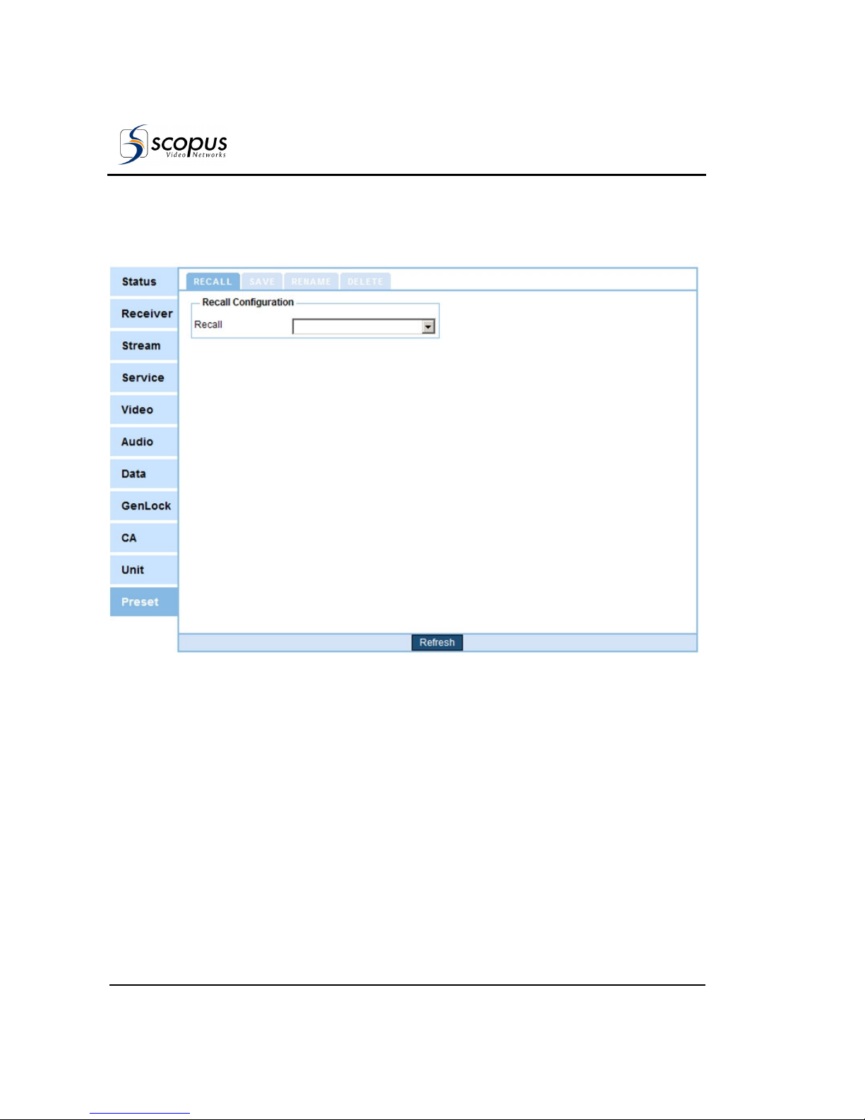
User Manual
Operation and Management
Page 4-2 (Rev. 4.6/ SW v1.80/ December 2007)
To access the Preset menu through the web-interface from the management
bar, click on the Preset tab.
The following figure shows the web-interface Preset menu:
Figure 4-1: Web Interface Preset Screen
The Preset menu consists of the following five submenus:
• Recall – For details see section 4.1.1.
• Save current – For details see section 4.1.2.
• Rename – For details see section 4.1.3.
• Delete – For details see section 4.1.4.
• Delete all – For details see section 4.1.5 (front-panel only).
The following sections detail the Preset submenus.
Page 89
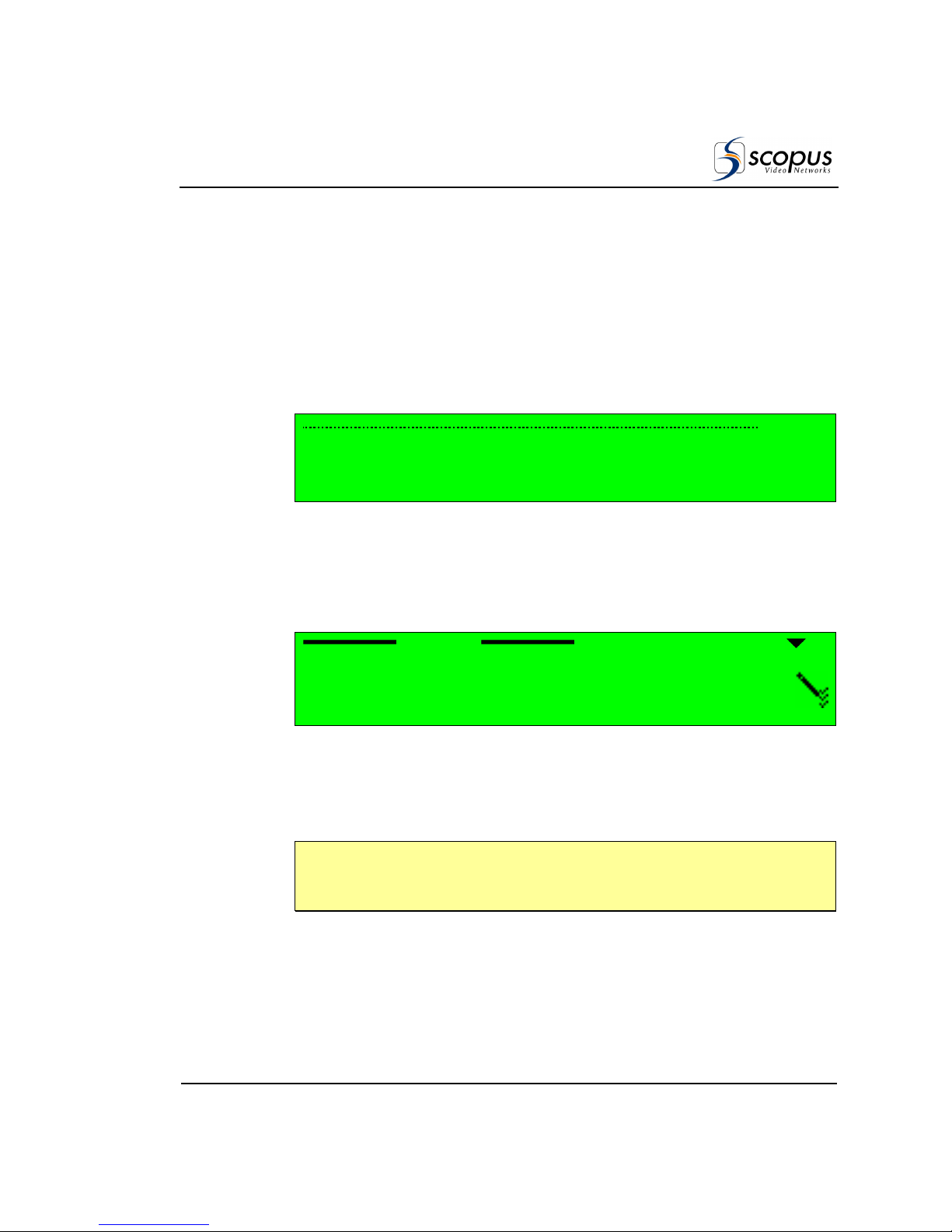
IRD-2900 Series
Professional Integrated Receiver Decoders
Scopus Documents (p/n 100793) Page 4-3
4.1.1. Recall Preset
Recall submenu allows loading saved presets from the unit's non-volatile storage.
To recall a preset though the front panel:
1. To access the Preset menu from the front panel go to:
Root
Preset
Recall.
The following figure shows the front panel Recall screen:
Name
Name Name
Name
1111
Default
DefaultDefault
Default
2
2 2
2
Setup_1
Setup_1Setup_1
Setup_1
3
3 3
3
Setup_2
Setup_2Setup_2
Setup_2
4
4 4
4
Setup_3
Setup_3Setup_3
Setup_3
The Recall screen lists all stored presets and allows selecting a preset to
recall.
2. Select one of the listed presets by using the [UP], [down] and [ENTER]
keys.
When selecting a preset to recall – the following screen appears:
Setup_1
Setup_1Setup_1
Setup_1
1111
RECALL
RECALLRECALL
RECALL
This screen shows the selected preset name at its title and the option
Recall.
3. Select the RECALL submenu tab.
N
OTE
When selecting a preset, the front panel's orange warning light might lit until the
unit is synced with the new setup applied.
Page 90
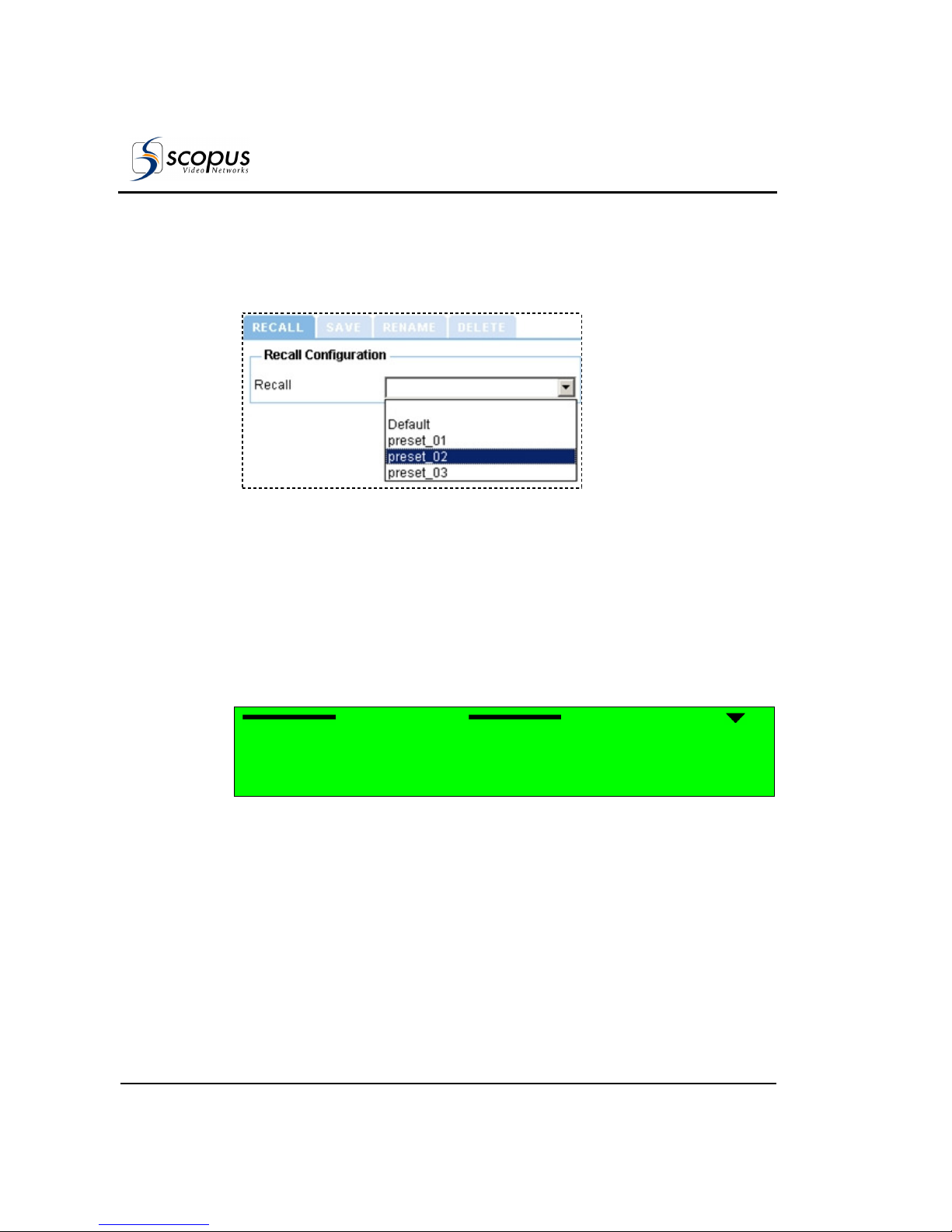
User Manual
Operation and Management
Page 4-4 (Rev. 4.6/ SW v1.80/ December 2007)
To recall a preset through the web-interface:
1. From the management bar, click the Preset tab.
2. Click Recall tab. Figure 4-2 shows the Recall tab:
Figure 4-2: Web Interface Preset Recall Tab
3. Open the Recall drop-down menu. From the list select a preset to recall.
4.1.2. Save Current Preset
The IRD-2900 can store up to 10 different setups. Save Current submenu
allows saving the unit's current setup. To access the Save Current menu through
the front panel, go to Root
Preset
Save Current.
The following figure shows the front panel Save Current submenu screen:
Save Current
Save CurrentSave Current
Save Current
1111----1111
1111
Overwrite Existing
Overwrite Existing Overwrite Existing
Overwrite Existing
2
2 2
2
New Name
New NameNew Name
New Name
To access the Save menu from the web-interface, go to Preset
Save.
Page 91
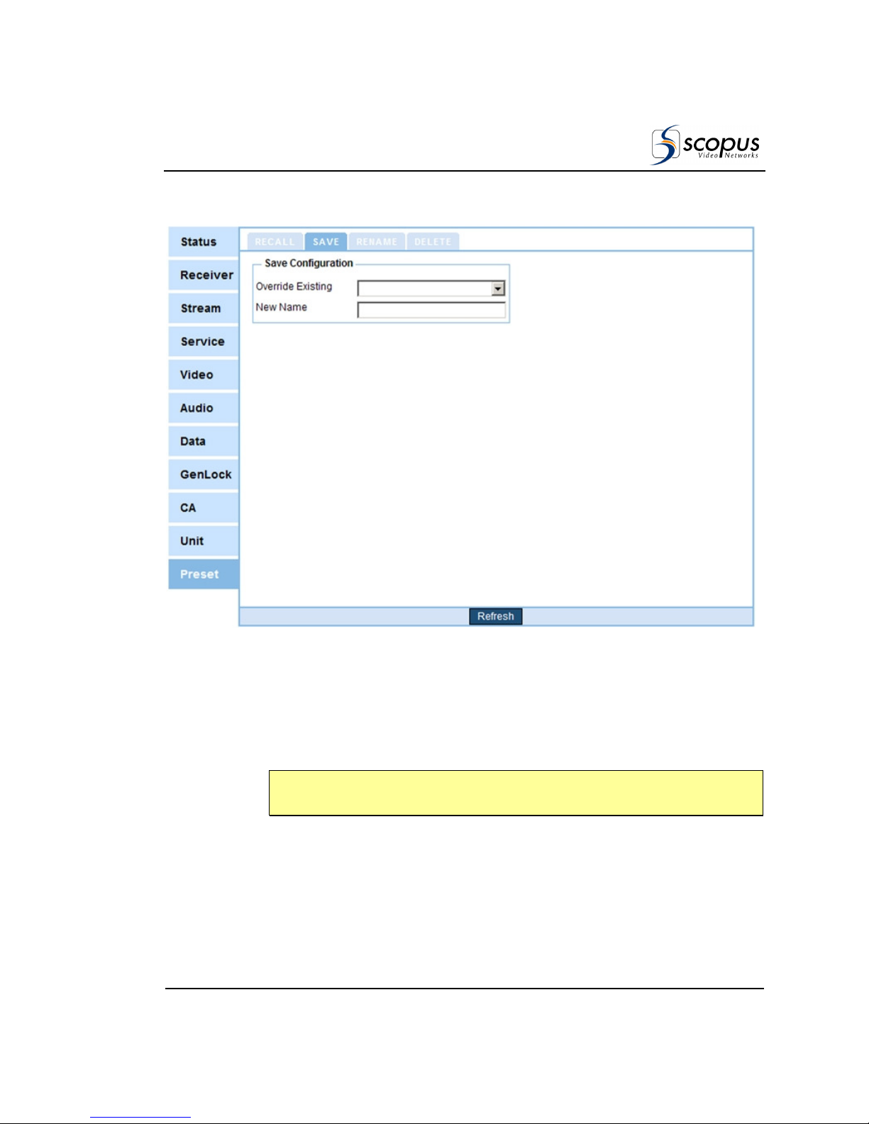
IRD-2900 Series
Professional Integrated Receiver Decoders
Scopus Documents (p/n 100793) Page 4-5
The following figure shows the web-interface Save submenu screen:
Figure 4-3: Web Interface Save Preset Screen
Save Current menu includes two options:
• Overwrite Existing –For details see section 4.1.2.1.
• New Name- –For details see section 4.1.2.2.
N
OTE
Scopus recommends storing the default manufacture's setup as a preset.
Page 92

User Manual
Operation and Management
Page 4-6 (Rev. 4.6/ SW v1.80/ December 2007)
4.1.2.1. Overwrite an Existing Preset
The Overwrite Existing option allows saving the unit's current setup over a
stored one.
To overwrite an existing preset through the front panel:
1. Access the Overwrite Existing screen. From the front panel go to
Root
Preset
Save Current
Overwrite Existing.
The following figure shows the front panel Overwrite Existing screen:
Name
Name Name
Name
1111
Default
DefaultDefault
Default
2
2 2
2
Setup_1
Setup_1Setup_1
Setup_1
3
3 3
3
Setup_2
Setup_2Setup_2
Setup_2
4
4 4
4
Setup_3
Setup_3Setup_3
Setup_3
The Overwrite Existing screen lists all stored presets and allows selecting a
preset to overwrite.
2. Select one of the listed presets by using the [UP], [DOWN] and [ENTER]
keys.
When selecting a preset to overwrite – the following screen appears:
Setup_1
Setup_1Setup_1
Setup_1
1111
OVERWRITE
OVERWRITEOVERWRITE
OVERWRITE
This screen shows the selected preset name at its title and the option
Overwrite.
3. Select OVERWRITE.
To overwrite an existing preset through the web-interface:
1. From the management bar, click on the Preset tab.
2. Click on Save tab. Figure 4-4 shows the Save tab:
Page 93
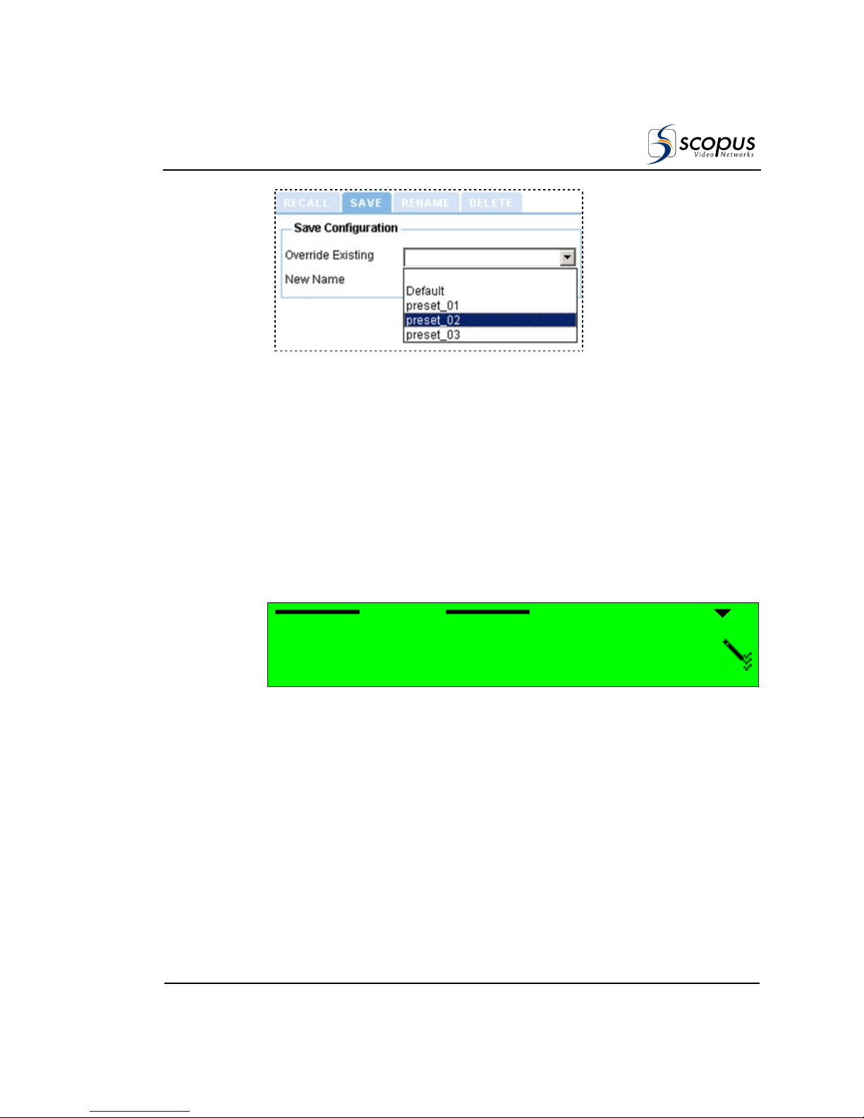
IRD-2900 Series
Professional Integrated Receiver Decoders
Scopus Documents (p/n 100793) Page 4-7
Figure 4-4: Web Interface Save Tab
3. Open the Overwrite Existing drop-down menu. From the list select a preset
to overwrite.
4.1.2.2. Name a New Preset
New Name option allows saving the unit's current setup under a new name.
To Name a new preset through the front panel:
1. Access the New Name screen. From the front panel go to:
Root
Preset
Save Current
New Name.
The following figure shows the front panel New Name edit screen:
New Name
New NameNew Name
New Name
||||
2. Name the preset by using the keypad. To select a character, use the [UP]
and [DOWN] keys. To move between the characters, use the [LEFT] and
[RIGHT] keys. To save, press [ENTER].
To name a new preset through the web-interface:
1. From the management bar, click on the Preset tab.
2. Click on Save tab. Figure 4-5 shows the New Name section:
Page 94
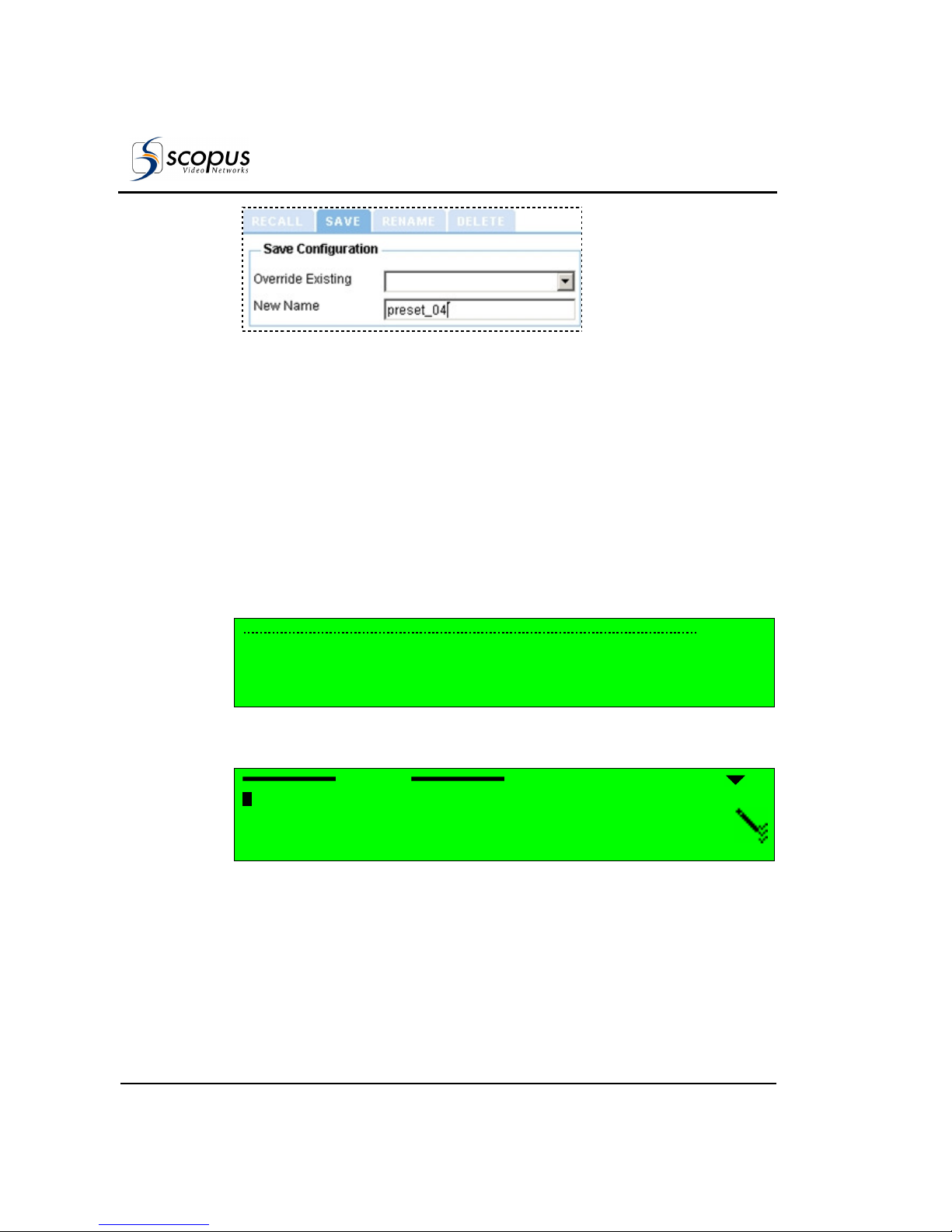
User Manual
Operation and Management
Page 4-8 (Rev. 4.6/ SW v1.80/ December 2007)
Figure 4-5: Web Interface – Save Preset As New Name Tab
3. Type a name for the preset in the New-Name textbox.
4. Press [ENTER] to finish.
4.1.3. Rename Preset
The Rename submenu allows editing a stored preset name.
To rename a preset through the front panel:
1. Access the Overwrite Existing screen. From the front panel go to
Root
Preset
Rename.
The following screen appears, lists all stored presets and allows selecting a
preset to rename.
Name
Name Name
Name
1111
Default
DefaultDefault
Default
2
2 2
2
Setup_1
Setup_1Setup_1
Setup_1
3
3 3
3
Setup_2
Setup_2Setup_2
Setup_2
4
4 4
4
Setup_3
Setup_3Setup_3
Setup_3
2. Select one of the listed presets by using the [UP], [DOWN] and [ENTER] keys.
When selecting a preset to rename – the Rename edit screen appears:
Rename
RenameRename
Rename
SSSSetup_1
etup_1etup_1
etup_1
3. Name the preset by using the keypad. To change a character, use the [UP]
and [DOWN] keys. To move between the characters, use the [LEFT] and
[RIGHT] keys. To save, press [ENTER].
To rename a preset through the web-interface:
1. From the management bar, click on the Preset tab.
Page 95
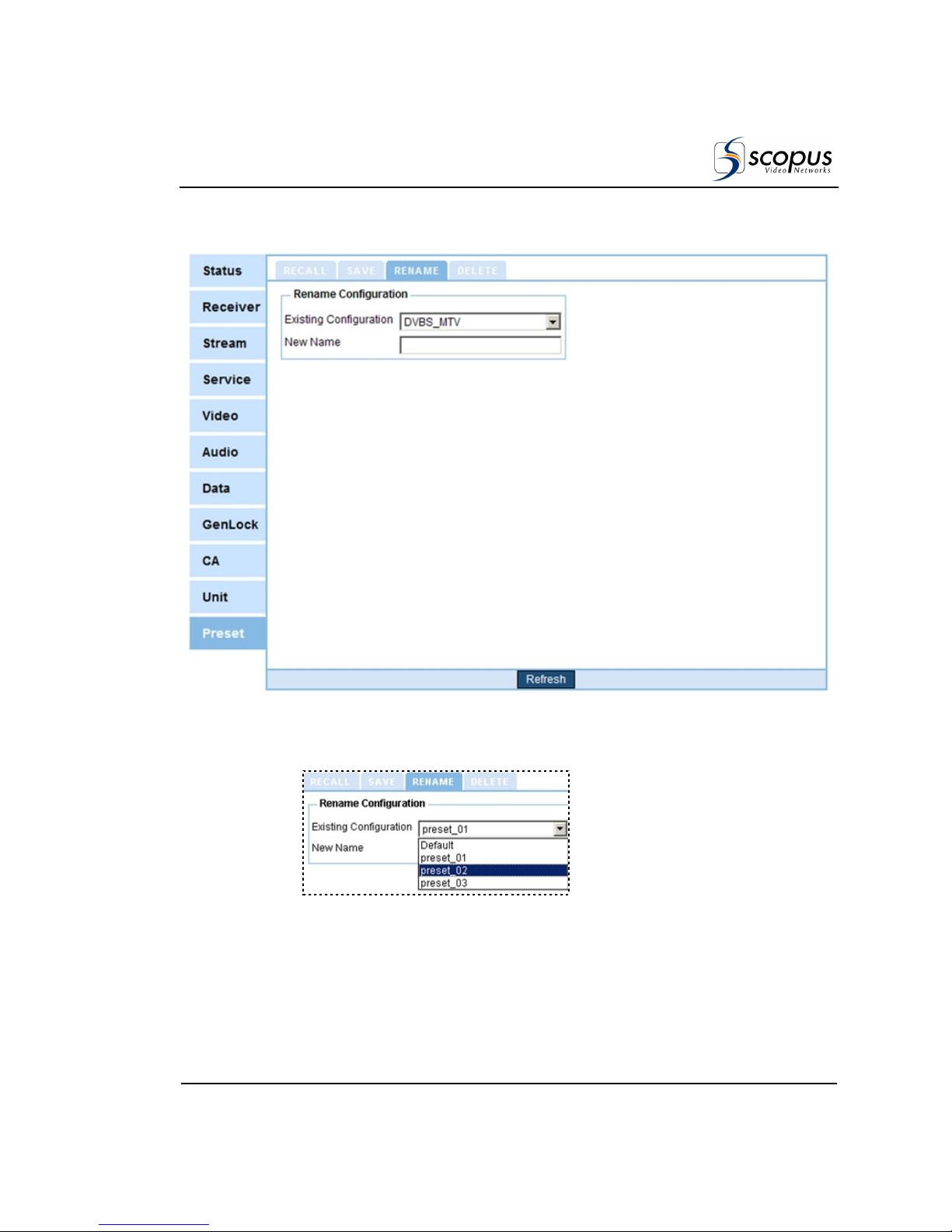
IRD-2900 Series
Professional Integrated Receiver Decoders
Scopus Documents (p/n 100793) Page 4-9
The following figure shows the web-interface Rename submenu screen:
Figure 4-6: Web Interface Rename Preset Screen
2. Click on Rename tab. Figure 4-7 shows the Rename tab:
Figure 4-7: Web Interface – Rename Preset Tab
3. Open the Existing Configuration drop-down menu. From the list select a
preset to rename.
4. Type a new name for the preset in the New-Name textbox.
Page 96

User Manual
Operation and Management
Page 4-10 (Rev. 4.6/ SW v1.80/ December 2007)
4.1.4. Delete Preset
The Delete submenu allows removing stored preset.
To delete a preset through the front panel:
1. Access the Delete screen. From the front panel go to Root
Preset
Save
Current
Delete.
The following screen appears, lists all stored presets and allows selecting a
preset to delete.
Name
Name Name
Name
1111
Default
DefaultDefault
Default
2
2 2
2
Setup_1
Setup_1Setup_1
Setup_1
3
3 3
3
Setup_2
Setup_2Setup_2
Setup_2
4
4 4
4
Setup_3
Setup_3Setup_3
Setup_3
2. Select one of the listed presets by using the [UP], [DOWN] and [ENTER]
keys.
When selecting a preset to delete – the following screen appears:
Setup_1
Setup_1Setup_1
Setup_1
1111
DELETE
DELETEDELETE
DELETE
This screen shows the selected preset name at its title and the option
Delete.
3. Select DELETE.
To delete a preset through the web-interface:
1. From the management bar, click on the Preset tab.
Page 97
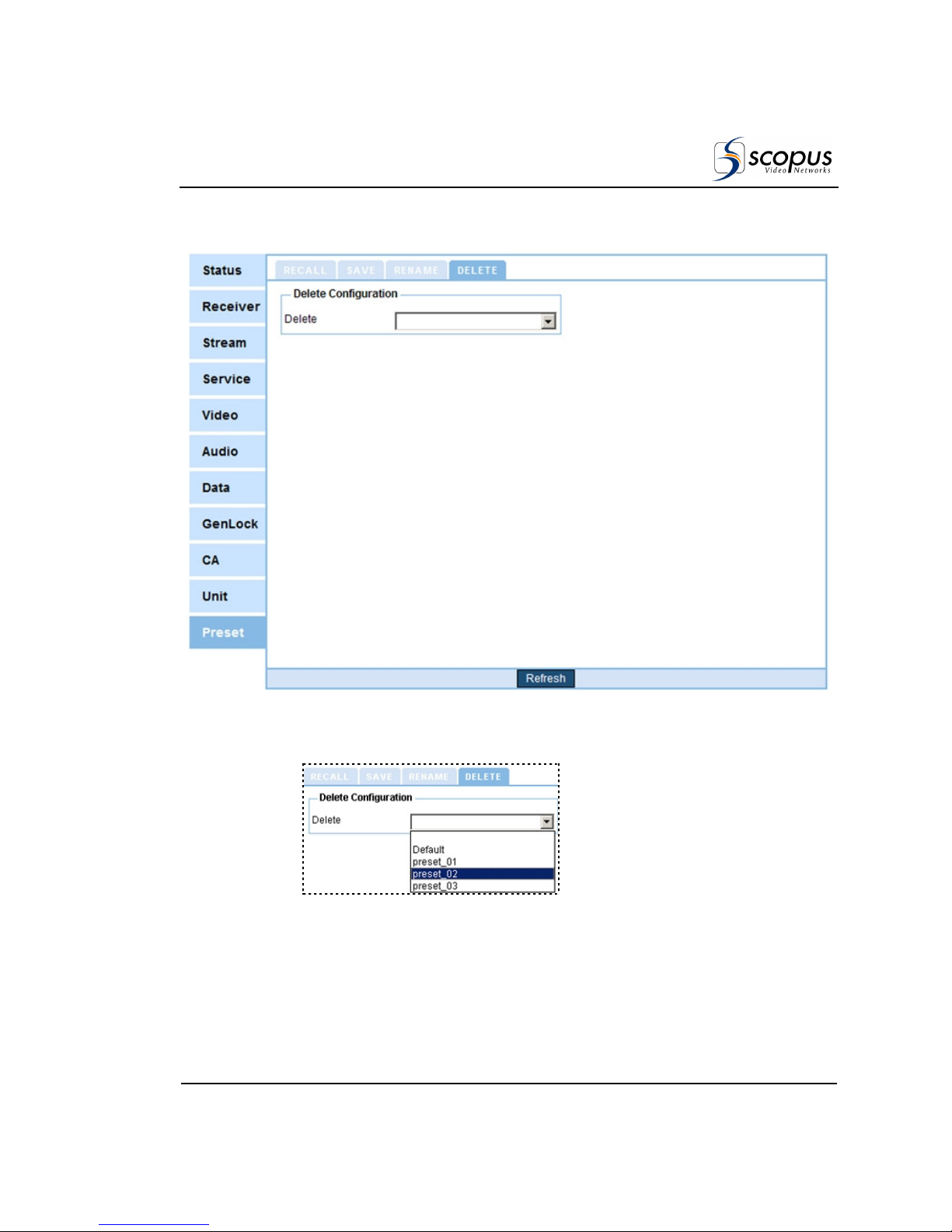
IRD-2900 Series
Professional Integrated Receiver Decoders
Scopus Documents (p/n 100793) Page 4-11
The following figure shows the web-interface Delete submenu screen:
Figure 4-8: Web Interface Delete Preset Screen
2. Click on Delete tab. Figure 4-9 shows the Delete tab:
Figure 4-9: Web Interface – Delete Preset Tab
3. Open the Delete drop-down menu. From the list select a preset to delete.
Page 98

User Manual
Operation and Management
Page 4-12 (Rev. 4.6/ SW v1.80/ December 2007)
4.1.5. Delete All Presets
The Delete All submenu allows removing all stored preset.
To delete all presets through the front panel:
1. Access the Delete screen. From the front panel go to Root
Preset
Save
Current
Delete All.
The following figure shows the front panel Delete All screen:
Delete All
Delete AllDelete All
Delete All
1111
OFF
OFFOFF
OFF
1111
ON
ONON
ON
Save Current menu includes two options:
• OFF –The function is disabled.
• ON- –Delete all stored presets.
2. Select ON.
Page 99
IRD-2900 Series
Professional Integrated Receiver Decoders
Scopus Documents (p/n 100793) Page 4-13
4.2. C
ONFIGURATION
The Configuration menu screen allows the user to manage the IRD-2900
through the front panel. The Configuration menu consists of eight sub-menus.
Each sub-menu manages a specific IRD module.
The following lists IRD-2900 configuration sub-menus:
• Receiver - For details, see Section 4.2.1.
• Stream - For details, see Section 4.2.3.
• Service - For details, see Section 4.2.4.
• Video - For details, see Section 4.2.6.
• Audio - For details, see Section 4.2.7.
• Data - For details, see Section 4.2.8.
• GenLock – For details, see Section 4.2.9.
• Conditional Access – For details, see Section 4.2.10.
• Unit - For details, see Section 4.2.11.
N
OTE
Sub-menus parameters may be vary from one model to another according to the
IRD-2900 technical specifications and licensing
Configuration
ConfigurationConfiguration
Configuration
1111----2222
1111
Receiver
Receiver Receiver
Receiver
2222
Stream
StreamStream
Stream
3333
Service
ServiceService
Service
4444
Video
VideoVideo
Video
5555
Audio
AudioAudio
Audio
6666
Data
DataData
Data
7777
Conditional Access
Conditional AccessConditional Access
Conditional Access
8888
Unit
UnitUnit
Unit
Figure 4-10: IRD-2900 Configuration Main Menu
Page 100
User Manual
Operation and Management
Page 4-14 (Rev. 4.6/ SW v1.80/ December 2007)
N
OTE
The IRD-2900 can support either IP or L-Band receiver modules. The
configuration menu structure changes according to each of these available
module options.
4.2.1. Receiver Modules
The purpose of the receiver module is to single out a selected Transport Stream
from the transmission that reaches the IRD-2900 inputs, to demodulate it, and
pass on the digital transport stream to the decoder module.
Different networks require various receiver types. According to its licensing, the
IRD-2900 supports two types of receivers:
1. Satellite Receiver Modules:
• DVB-S Receiver Module The configuration parameters of the DVB-S
receiver module are detailed in Section 4.2.2.1.
•
DVB-S2 Receiver Module
The configuration parameters of the
DVB-S2 receiver module are detailed in Section 4.2.2.2.
• DSNG Module The configuration parameters of the DSNG receiver
module are detailed in Section 4.2.2.3.
• ATM Module The configuration parameters of the ATM receiver module
are detailed in Section 4.2.2.4.
2. IP Receiver Module: The configuration parameters of the IP receiver
module are detailed in Section 4.2.2.5.
To access the Receiver Configuration menu using the front panel, select
ConfigurationReceiver (independently of the receiver module type).
 Loading...