


CODICO® E-1710
COMPACT DSNG ENCODER
User Manual
Pub. No. 1000401
(Rev. A / June 2003)


Scopus Network Technologies Inc.
U.S. Offices
Scopus Network Technologies Ltd.
International Headquarters
100 Overlook Center Drive, 3rd Floor
Princeton, NJ 08540.
USA
Tel: (609)-987-8090
Fax: (609)-987-8095
Email:
info@scopususa.com
Web: www.scopususa.com
10 Ha’amal St., Park Afek
Rosh Ha’ayin, 48092
Israel
Tel: (972) –3-9007777
Fax: (972) –3-9007888
Email:
info@scopus.net
Web: www.scopus.net
© 2001 Scopus Network Technologies Ltd. All rights reserved.
Scopus Network Technologies Ltd. Reserves the rights to alter the equipment specifications and
descriptions in this publication without prior notice. No part of this publication shall be deemed to be
part of any contract or warranty unless specifically incorporated by reference into such contract or
warranty.
The information contained herein is merely descriptive in nature, and does not constitute a binding
offer for sale of the product described herein.
®
CODICO
is a Registered trademark of Scopus Network Technologies Ltd. In Israel, Germany, France,
U.K., U.S.A. and Japan. All references to registered trademarks of other vendors are the property of
their respective owners.
File E-1710 User Rev A.doc Saved 25/06/2003 14:13


E-1710
Compact DSNG Encoder
INTRODUCTION
Scopus Network Technologies Ltd. takes great pride in delivery of its products, and makes
every endeavor to ensure its clients full satisfactory.
On behalf of all the Scopus team, we would like to extend our congratulations on your
investment in the CODICO
E-1710 Compact DSNG Encoder.
E-1710 COMPACT DSNG ENCODER
MANUAL SCOPE AND STRUCTURE
The User Manual for the CODICO E-1710 Compact DSNG Encoder provides instructions
for qualified installation, service and operation technicians to facilitate optimum
performance of the E-1710 in a Digital Video Broadcasting System. The manual is
comprised of five main sections:
1. OVERVIEW:
This section provides introduction and product description, including highlights,
benefits and typical applications, gives a functional and physical description of the unit
and lists its main capabilities and specifications.
2. INSTALLATION:
This section provides data and procedures required to install and activate the unit.
Procedures include site preparation and requirements, installation in a 19" rack, cable
connections, panel options and Pin-out descriptions, initial settings and serviceability
check.
3. FRONT PANEL OPERATION:
This section provides theoretical background on the operation of the unit, and gives
data and instructions on using the unit and operating the control and monitoring
functions provided to the user from the E-1710 Front Panel.
4. ADVANCED OPERATION
This section provides advanced information for operating high-level options, including
software installation and updating, remote control via SNMP and configuration using
VI tools
5. MAINTENANCE
This section provides instructions and directives for performing operational tests on
the encoder and troubleshooting basic failures in the system.
It is assumed throughout this document that personnel have a general knowledge about
the E-1710 Compact DSNG Encoder, application and capabilities.
®
General knowledge of the CODICO
detailed information, refer to the CODICO
documents.
System and its application is also assumed. For
®
MPEG-2 DVB Family Product Description
Pub. No. 1000401 Page i
CODICO® MPEG-2 DVB Family Line
User Manual
Front Matter
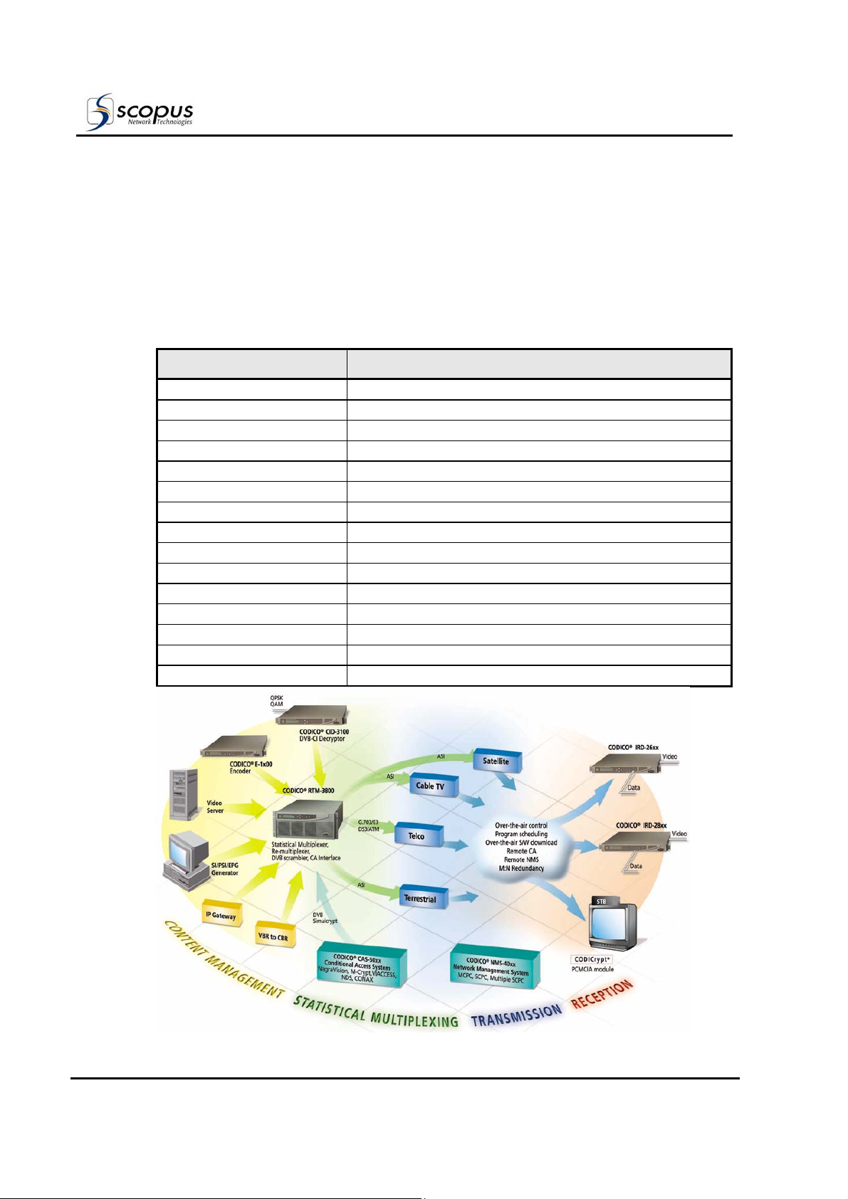
The E-1710 Compact DSNG Encoder is an integral member of the advanced CODICO
product line. The CODICO
transmission sites and reception stations. In addition, it is the most cost-effective solution
for TV broadcasting applications. The following table lists the CODICO
the illustration shows the integration of the product line in a DVB environment.
CODICO
PRODUCT DESCRIPTION
E-900 Industrial Encoder
E-1000/E-1100 Professional Encoders
E-1510 DSNG Exciter
E-1710 Compact DSNG Encoder
IRD-2600/IRD-2800 Advanced Professional Integrated Receiver Decoders
CID-3100 Common Interface Decryptor
RTM-3300 Compact DVB Re-Multiplexer and Stream Processor
RTM-3800 DVB Multiplexer
IVG-6100 IP Broadcast Streamer
RSW-8x00 Redundancy Switches
MOD-8610 DSNG Modulator and Up-Converter
NMS-4000 Complete Network Management System
CAS-5000 Conditional Access System
SM-3000 Statistical Multiplexing System
SI-3050 PSI/SI Generator Application
product family offers comprehensive solutions for both
®
®
Product Family
product family and
Page ii
Pub. No. 1000401

E-1710
Compact DSNG Encoder
TECHNICAL SUPPORT
In case of technical problems with the CODICO system or one of its components, refer to
the System Documentation. In most instances, this may save you time in resolving
technical difficulties.
Should you not be able to resolve the problem, call your local distributor for technical
support.
HOW TO RETURN FAULTY PARTS
Before returning an item:
1. Request a RMA (Return Merchandise Authorisation) Tracking Number from your local
Distributor.
2. Scopus Network Technologies support will assign a RMA Tracking Number; this must
accompany the item being returned and will be referred to in all correspondence.
3. The item is sent to Scopus Network Technologies with the RMA Number included in
the accompanying documentation (shipping and customs forms).
Customer Support Point Of Contact (POC)
Scopus Network Technologies
Inc.
U.S. Offices
Scopus Network Technologies Ltd.
International Headquarters
100 Overlook Center Drive, 3rd Floor
Princeton, NJ 08540.
USA
Tel: (609)-987-8090
Fax: (609)-987-8095
Email: support@scopus.net
Web: www.scopus.net
10 Ha’amal St., Park Afek
Rosh Ha’ayin, 48092
Israel
Tel: (972) –3-9007777
Fax: (972) –3-9007888
Pub. No. 1000401 Page iii

WARRANTY
SCOPUS Network Technologies Ltd. warrants that the Product and any part thereof,
including, but not limited to spare parts, will, when properly installed, conform to SCOPUS
Network Technologies Ltd. published specifications and that the Product and any parts
thereof, including, but not limited to, spare parts, will be free from defects deriving from
wrong workmanship and faulty materials under normal use and service, for a period of
twelve (12) months following the date of manufacture thereof.
The supply of spare parts at reasonable cost shall be available for a period of three (3)
years from the date of delivery.
This warranty does not cover ordinary wear and tear of the Product or other defects due to
circumstances beyond SCOPUS Network Technologies Ltd. control such as unsuitable
operating means, chemical, Electro-mechanical or electrical influences and damages which
may be caused by interference by the CUSTOMER or any unauthorized third party.
Defective cards/assemblies will be sent to SCOPUS Network Technologies Ltd. for repair.
The repaired cards/assemblies will be returned to the CUSTOMER within 30 days from
their receipt by SCOPUS Network Technologies Ltd.
Cards/assemblies repaired during the 12 months warranty period will carry a warranty of
6 months from date of repair or until end of original warranty period, whichever is the
later date.
SCOPUS Network Technologies Ltd. sole liability under this warranty shall be limited to the
repair or replacement with equivalent units at SCOPUS Network Technologies Ltd.
facilities, of any Product or parts thereof that do not conform to SCOPUS Network
Technologies Ltd. published specifications or that are defective in material or
workmanship, as specified above. The expense of installing repaired or replaced parts
shall be borne by the CUSTOMER.
SCOPUS Network Technologies Ltd. sole obligation under this Warranty is be the supplier
of the Product to the CUSTOMER and to provide such services as set out in this Warranty
on the SCOPUS Network Technologies Ltd. terms and conditions provided for herein. In no
event will SCOPUS Network Technologies Ltd. be liable to the CUSTOMER for any business
expenses, loss of profits, incidental, indirect or consequential damages, however caused,
unless such expenses, loss or damages shall have derived from an infringement of patents
of copyrights.
THE WARRANTIES STATED HEREIN ARE EXCLUSIVE AND ARE EXPRESSLY IN LIEU OF ALL
OTHER WARRANTIES, EXPRESSED OR IMPLIED, INCLUDING, BUT NOT LIMITED TO, THE
IMPLIED WARRANTY OF MERCHANTABILITY OR FITNESS FOR A PARTICULAR PURPOSE.
Beyond the warranty period, SCOPUS Network Technologies Ltd. shall repair or replace
defective cards/assemblies according to its standard price list relevant at such time.
Cards/assemblies thus repaired shall carry a warranty of 6 months.
User Manual
Front Matter
Page iv
Pub. No. 1000401

E-1710
Compact DSNG Encoder
TABLE OF CONTENTS
1. Overview ............................................................................................. 1-1
1.1.
1.2. Functional Description ............................................................................... 1-7
1.3. Mechanical Structure............................................................................... 1-12
1.4. Interfaces.............................................................................................. 1-14
1.5. Management .......................................................................................... 1-20
1.6. Capabilities and Specifications.................................................................. 1-22
General Information.................................................................................. 1-1
1.1.1. Highlights and Benefits................................................................. 1-2
1.1.2. Applications ................................................................................ 1-5
1.1.2.1. Single Path DSNG Uplink Application............................... 1-5
1.1.2.2. Dual Path DSNG Uplink Application ................................. 1-5
1.1.2.3. Triple Path DSNG Uplink Application ............................... 1-6
1.1.2.4. Input Encoding Capability.............................................. 1-6
1.2.1. Basic Configuration Features ......................................................... 1-7
1.2.1.1. E-900 Based E-1710 DSNG Encoder ............................... 1-7
1.2.1.2. E-1000 Based E-1710 DSNG Encoder.............................. 1-8
1.2.1.3. E-1100 Based E-1710 DSNG Encoder.............................. 1-8
1.2.2. E-1710 DSNG Encoder Custom Configuration Options ...................... 1-9
1.2.3. Functional Architecture ............................................................... 1-11
1.3.1. Enclosure ................................................................................. 1-12
1.3.2. Front Panel ............................................................................... 1-12
1.3.3. Rear Panel ................................................................................ 1-12
1.4.1. Video Input Interfaces................................................................ 1-14
1.4.1.1. Composite/Component Video Input Panel (Option) ......... 1-14
1.4.1.2. Composite/SDI Video Input Panel (Option) .................... 1-15
1.4.2. Audio Input Interfaces................................................................ 1-17
1.4.2.1. Standard Audio-1 and Audio-2 Inputs ........................... 1-17
1.4.2.2. Optional Audio-3 and Audio-4 Inputs ............................ 1-17
1.4.3. Encoder Data Input Interfaces..................................................... 1-17
1.4.4. E-1710 Output Interfaces ........................................................... 1-18
1.4.4.1. ASI Output Interface .................................................. 1-18
1.4.4.2. Modulated IF Output Interface ..................................... 1-18
1.4.4.3. L-Band Monitor Output Interface .................................. 1-18
1.4.4.4. DVB Scrambling Output Interface Option....................... 1-18
1.4.4.5. RS-422 Output Interface ............................................. 1-18
1.4.5. Encoder Control Interfaces.......................................................... 1-19
1.4.5.1. DATA Interface .......................................................... 1-19
1.4.5.2. Ethernet Interface ...................................................... 1-19
1.4.5.3. Monitor Output .......................................................... 1-19
1.4.5.4. GPI Interface ............................................................. 1-19
1.5.1. Front Panel Control .................................................................... 1-20
1.5.2. TFTP Interface........................................................................... 1-20
1.5.3. ASCII....................................................................................... 1-20
1.5.4. SNMP Management .................................................................... 1-21
1.6.1. Capabilities ............................................................................... 1-22
1.6.2. Interface Connections Specifications ............................................ 1-24
1.6.3. Physical Specifications................................................................ 1-26
Pub. No. 1000401 Page v

User Manual
Front Matter
2.
3. Front Panel Operation........................................................................... 3-1
Installation...........................................................................................2-1
2.1.
2.2.
2.3.
2.4.
2.5.
2.6.
3.1. General................................................................................................... 3-1
3.2. Configuration Menu .................................................................................. 3-6
3.3. Status Menu ...........................................................................................3-21
3.4. Test Menu ..............................................................................................3-24
3.5. Modulator Menu ......................................................................................3-25
General ................................................................................................... 2-1
Installation Information............................................................................. 2-1
2.2.1. Safety Precautions....................................................................... 2-1
2.2.2. Inventory Check.......................................................................... 2-1
2.2.3. Site Preparation .......................................................................... 2-2
Mechanical Installation .............................................................................. 2-2
2.3.1. Rack Mounting ............................................................................ 2-2
2.3.2. Compact Flash Installation............................................................ 2-3
Electrical Installation................................................................................. 2-3
2.4.1. Power and Ground....................................................................... 2-3
2.4.1.1. AC Power Supply.......................................................... 2-3
2.4.1.2. DC Power Supply ......................................................... 2-4
2.4.2. Cabling Connections .................................................................... 2-4
2.4.3. Encoder Cascading Connections .................................................... 2-5
Quick Start .............................................................................................. 2-6
2.5.1. Power Up Sequence ..................................................................... 2-6
2.5.2. Preprogram Setups...................................................................... 2-7
2.5.3. Initial Configuration ..................................................................... 2-7
Serviceability Checks ................................................................................ 2-8
2.6.1. Video Serviceability Check............................................................ 2-8
2.6.2. Audio Serviceability Check............................................................ 2-9
2.6.3. Modulator Serviceability Test ........................................................ 2-9
3.1.1. Front Panel Operation .................................................................. 3-1
3.1.2. Front Panel Menu - Parameters Management Concept ...................... 3-2
3.1.3. Front Panel Menu ........................................................................ 3-4
3.2.1. ConfigÆVideo Menu..................................................................... 3-7
3.2.2. ConfigÆAudio Menu....................................................................3-10
3.2.3. ConfigÆAuxiliary Menu ...............................................................3-11
3.2.4. ConfigÆService Menu .................................................................3-14
3.2.4.1. ConfigÆServiceÆAdvanced Sub-Menu ...........................3-14
3.2.4.2. ConfigÆServiceÆA/D Sub-Menu ...................................3-17
3.2.4.3. ConfigÆServiceÆOther Sub-Menu.................................3-19
3.3.1. StatusÆSystem Menu .................................................................3-22
3.3.2. StatusÆGeneral Menu.................................................................3-23
4. Advanced Operation .............................................................................4-1
Page vi
4.1.
4.2.
4.3.
4.4. Modulator Configuration ...........................................................................4-22
General ................................................................................................... 4-1
System Software Management ................................................................... 4-1
4.2.1. Formatting the Flash Disk............................................................. 4-1
4.2.2. System Software Installation and Upgrade Procedures ..................... 4-2
4.2.2.1. Software Installation/Upgrade Procedure ........................ 4-2
4.2.2.2. Copying Files using Serial Connection (RS-232) ............... 4-3
4.2.2.3. Copying Files using TFTP Tools....................................... 4-4
Encoder Configuration............................................................................... 4-6
4.3.1. Using VI Editor to Edit the Configuration File................................... 4-6
4.3.2. Encoder Configuration File ............................................................ 4-9
4.3.3. Manual Configuration Information.................................................4-17
Pub. No. 1000401

E-1710
Compact DSNG Encoder
4.5.
DVB Scrambling & Encoder Based Encryption ............................................. 4-23
4.5.1. Encoder Based Encryption .......................................................... 4-24
4.5.2. Fixed-Key DVB Scrambling ......................................................... 4-24
4.5.3. BISS and BISS-E Scrambling System ........................................... 4-25
4.5.4. DVB Scrambling Memory Structure .............................................. 4-25
4.5.5. DVB Scrambler Configuration Parameters ..................................... 4-26
4.6. SNMP Management ................................................................................. 4-27
4.6.1. SNMP Configuration ................................................................... 4-27
4.6.2. SNMP Management Information Bases (MIBs) ............................... 4-27
4.6.3. SNMP Parameter Property Sheet.................................................. 4-28
4.6.4. E-1710 SNMP Agent Traps .......................................................... 4-30
5. Maintenance ........................................................................................ 5-1
5.1.
5.2.
5.3.
5.4. Status and Diagnostic Messages ................................................................. 5-5
5.5. Rear Panel Connectors – Pin Assignment ..................................................... 5-8
General ................................................................................................... 5-1
Safety Instructions ................................................................................... 5-1
Test Procedures........................................................................................ 5-2
5.3.1. Power-Up Check. ......................................................................... 5-2
5.3.2. Serviceability Check..................................................................... 5-3
5.3.2.1. Video Serviceability Check............................................. 5-3
5.3.2.2. Audio Serviceability Check............................................. 5-4
5.3.2.3. Modulator Serviceability Test ......................................... 5-4
5.4.1. Front Panel Status Messages......................................................... 5-5
5.4.1.1. Fail To Comply Messages............................................... 5-5
5.4.1.2. Encoder Warning Messages ........................................... 5-6
5.4.2. Encoder Status Messages ............................................................. 5-7
Pub. No. 1000401 Page vii

User Manual
Front Matter
LIST OF FIGURES
Figure 1-1: The E-1710 Compact DSNG Encoder – General View .................................. 1-1
Figure 1-2: The E-1710 Compact DSNG Encoder – Basic Application............................. 1-1
Figure 1-3: Single Path DSNG Uplink Application ......................................................... 1-5
Figure 1-4: Dual Path DSNG Uplink Application ........................................................... 1-5
Figure 1-5: Triple Path DSNG Uplink Application.......................................................... 1-6
Figure 1-6: E-1710 Compact DSNG Encoder in an SCPC application............................... 1-6
Figure 1-7: E1710 Layout – Option Location ............................................................. 1-10
Figure 1-8: E-1710 DSNG Encoder - Functional Block Diagram ................................... 1-11
Figure 1-9: Front View of the E-1710 DSNG Encoder ................................................ 1-12
Figure 1-10: E-1710 DSNG Encoder - Rear View ........................................................ 1-12
Figure 1-11: Composite/Component Video Input Panel ................................................ 1-14
Figure 1-12: Composite/SDI Video Input Panel .......................................................... 1-15
Figure 1-13: Composite Video Input Panel ................................................................ 1-15
Figure 1-14: SDI Video Input Panel .......................................................................... 1-15
Figure 1-15: E-1710 Audio Input Options .................................................................. 1-17
Figure 1-16: E-1710 Data Input Options ................................................................... 1-17
Figure 1-17: E-1710 Output Options ........................................................................ 1-18
Figure 1-18: E-1710 Control Interfaces Connections................................................... 1-19
Figure 2-1: E-1710 Compact Flash Receptacle ........................................................... 2-3
Figure 2-2: E-1710 Rear Panel, AC Power Connection ................................................. 2-3
Figure 2-3: E-1710 Rear Panel, DC Power Connection................................................. 2-4
Figure 2-4: E-1710 Typical Rear Panels – Connectors Location..................................... 2-4
Figure 2-5: RS-422 Cascading – Cable Connections .................................................... 2-5
Figure 2-6: E-1710 Panel Initialization Sequence ........................................................ 2-6
Figure 3-1: Front View of the Encoder....................................................................... 3-1
Figure 3-2: E-1710 Front Panel Menu - Structure ....................................................... 3-4
Figure 3-3: Encoder Configuration Menu tree ............................................................. 3-6
Figure 3-4: Encoder Status Menus........................................................................... 3-21
Figure 3-5: Encoder Test Menus............................................................................. 3-24
Figure 3-6: Modulator (Modem) Menu...................................................................... 3-25
Figure 4-1: RS-232 Connection Topology .................................................................. 4-3
Figure 4-2: TFTP Connection Topology ...................................................................... 4-4
Figure 4-3: Memory Structure of Keys .................................................................... 4-25
Figure 4-4: Encoder Parameter Property Sheet - Example 1 ....................................... 4-29
Figure 4-5: Encoder Parameter Property Sheet – Example 2 ....................................... 4-29
Figure 5-1: E-1710 DSNG Encoder - Panel Initialization Sequence ................................. 5-2
Page viii
Pub. No. 1000401

E-1710
Compact DSNG Encoder
LIST OF TABLES
Table 1-1:
Table 1-2:
Table 1-3:
Table 1-4:
Table 1-5:
Table 1-6:
Table 1-7:
Table 1-8:
Table 1-9:
Table 1-10: E-1710 Electrical Requirements ............................................................. 1-26
Table 1-11: E-1710 Environmental Conditions .......................................................... 1-26
Table 2-1:
Table 2-2:
Table 2-3:
Table 3-1: Interfaces of the Front Control Panel ........................................................ 3-1
Table 3-2: Encoder Front Panel – Main menu Options .................................................3-5
Table 3-3: ConfigÆVideo Menu Options.....................................................................3-7
Table 3-4: ConfigÆAudio Menu Options ................................................................. 3-10
Table 3-5: ConfigÆAuxiliary Menu. Options ............................................................ 3-11
Table 3-6: ConfigÆServiceÆAdvanced Sub-Menu Options ......................................... 3-14
Table 3-7: ConfigÆServiceÆA/D Sub-Menu Options ................................................. 3-17
Table 3-8: ConfigÆServiceÆOther Sub-Menu Options ............................................... 3-19
Table 3-9: StatusÆSystem Menu Options................................................................ 3-22
Table 3-10: StatusÆGeneral Menu Options ............................................................... 3-23
Table 3-11: Test Menu Options ............................................................................... 3-24
Table 3-12: Modem Menu Options............................................................................ 3-26
Table 4-1: VI Editor Modes .....................................................................................4-7
Table 4-2: VI Commands and Syntax.......................................................................4-7
Table 4-3: Encoder Configuration Parameters ........................................................... 4-9
Table 4-4: Manual Encoder Configuration Parameter................................................ 4-17
Table 4-5: Modulator Configuration Parameters ...................................................... 4-22
Table 4-6: DVB Scrambling vs. Encoder Based Encryption Comparison ...................... 4-23
Table 4-7: DVB Scrambler Configuration Parameters ............................................... 4-26
Table 4-8: E-1710 Private MIB Table Description...................................................... 4-27
Table 4-9: E-1710 SNMP Agent Traps ..................................................................... 4-30
Table 5-1 Fail To Comply Messages .........................................................................5-5
Table 5-2 Fail To Comply Messages .........................................................................5-6
Table 5-3: ANALOG 1/2 L/R Interface Pin-to-Signal Assignment .................................. 5-8
Table 5-4: GPI Interface Pin-to-Signal Assignment .................................................... 5-8
Table 5-5: HSD Interface Pin-to-Signal Assignment ...................................................5-8
Table 5-6: Monitor Interface Pin-to-Signal Assignment...............................................5-8
Table 5-7: Data Control (RS-232) Interface Pin-to-Signal Assignment.......................... 5-9
Table 5-8: RS-422 Output 1 Connection Interfaces Pin-to-Signal Assignment ...............5-9
Table 5-9: RS-422 Output 2 Connection Interfaces Pin-to-Signal Assignment ................ 5-9
Table 5-10: Audio Channel 3,4 Connector (Option). ................................................... 5-10
E-1710 Configuration Options................................................................... 1-9
E-1710 Typical Connector Interfaces ...................................................... 1-13
Composite/Component Video Input Panel Elements................................... 1-14
Composite/SDI Video Input Panel Elements ............................................. 1-16
E-1710 Encoder Capabilities .................................................................. 1-22
Input Connection Interfaces .................................................................. 1-24
Output Connection Interfaces................................................................ 1-25
Control Connection Interfaces ............................................................... 1-25
E-1710 Compact DSNG Encoder Mechanical Dimensions ........................... 1-26
E-1710 Compact DSNG Encoder Inventory List ..........................................2-1
E-1710 Status Indicator LED Legend .........................................................2-7
PARAMETERS WERE MODIFIED Auto Prompt ............................................. 2-7
Pub. No. 1000401 Page ix


E-1710
Compact DSNG Encoder
1. OVERVIEW
1.1. General Information
The CODICO E-1710 Compact DSNG Encoder is a fully integrated MPEG-2 4:2:2
encoder/modulator in a 1 RU high unit, thus, it is particularly suitable for the fast-moving
world of digital satellite/earth news gathering (DSNG/DENG) contribution applications.
The E-1710 features, within the compact 1U enclosure, an advanced professional
broadcast quality encoder and a software modifiable QPSK, 8PSK 16QAM with embedded
L-Band Monitoring and a COFDM modulator (optional).
The E-1710 is a rugged, power efficient and user-friendly encoder/modulator. It is fully
compliant to both 4:2:0 and 4:2:2 DVB standards, ensuring best picture quality at a
competitive price in a compact unit. Figure 1-1 illustrates the E-1710.
Figure 1-1: The E-1710 Compact DSNG Encoder – General View
The E-1710 compact size and weight make it ideal for both Satellite Newsgathering
Vehicles as well as Flyaway packages, operating in either C- or Ku-band. For any type of
SNG uplink system, the E-1710 fits neatly into the rack, occupying only 1U with no need
to provide space for ventilation above or below.
Using the analog and/or the optional SDI digital input, the E-1710 can feed directly to the
upconverter, thus providing a very compact uplink package with only three components –
the E1700, a 70 MHz to SHF Upconverter and a High Power Amplifier (HPA).
The L-band Monitoring Output, provided by the E-1710, enables “on the spot” real-time
monitoring of the modulated transmit information.
A typical, basic application diagram of a SNG station with local monitoring feature is
provided in Figure 1-2.
Figure 1-2: The E-1710 Compact DSNG Encoder – Basic Application
A/V
MONITOR
HPA
Analog or SDI
E-1710 COMPACT
DSNG ENCODER
L-Band
IF
IRD DECODER
70 MHZ - SHF
UP CONVERTER
Pub. No. 1000401 Page 1-1

1.1.1. Highlights and Benefits
The E-1710 offers 10 bit coding at data rates of up to 25 Mbps (up to 52 Mbps rate is
available as an option) while the versatile on-board modulator can handle QPSK
transmissions with 8-PSK or 16-QAM modes as an option. A variety of video resolutions
are available as standard, as is advanced DNR (Digital Noise Reduction).
The E-1710 also offers a DVB-compliant Low-Delay mode in either 4:2:0 or 4:2:2 format
for critical ‘pieces-to-camera’ seasons, without awkward pauses in broadcasting. A special
Ultra-Low mode is provided for the 4:2:2 format.
Offering 70 MHz output, the E-1710 can be installed remote from the Up Converter/HPA
package, enabling cross-site distances in excess of 25 meters if required (dependent upon
cable type). The L-band Monitoring Output provides local monitoring of the modulated
output.
The Front Panel Operating Menu provided by the E-1710 is specifically tailored to SNG,
with frequently used operation critical controls such as ‘carrier on/off’ and ‘modulation
on/off’ available via ‘hot-keys’ on the front panel four way touch pad. This allows the
operator to get up onto or off the satellite rapidly. This feature, combined with the facility
to store up to 10 pre-set configurations, gives the E-1710 unrivalled flexibility for the busy
operator.
E-1710 handles up to four full quality stereo audio channels (or up to 8 mono channels) as
either analogue/embedded/AES inputs, with a range of sampling rates and coding rates of
up to 384 Kbps.
The E-1710 features fully compliant BISS (Basic Interoperability Scrambling System) in
either BISS Mode 1 or BISS-E to protect those all-important transmissions using the
industry security standard.
The E-1710 provides multi-channel encoder cascading. This standard facility enables a
single Master E-1710 DSNG Encoder and up to three Slaved CODICO
Encoders to be configured to offer a single-stream output containing multiple programs.
This offers an ideal solution for multi-channel systems and saves the cost of a separate
multiplexing device.
Following is a detailed list of the capabilities and benefits provided by the CODICO
1710 Compact DSNG Encoder.
Encoding Profiles 4:2:2 Professional Profile Main Level
4:2:0 Main Profile Main Level
DVB QPSK
Modulator
Alternative
Modulation
Schemes
(options)
L-Band Monitoring
Output
Built-in SCPC DVB QPSK Modulator for DSNG applications.
Optional Software modifiable modulation schemes are:
8PSK: Suitable for satellite transponders driven near
saturation.
16QAM: Provides improved spectrum efficiency for linear
transponders.
COFDM: for digital terrestrial transmission.
Provides real-time local monitoring of the modulated
receive/transmit information.
User Manual
Chapter 1. Overview
®
E-1000 Professional
®
E-
Page 1-2
BISS (DSNG-CA)
(option)
The E-1710 supports BISS (DSNG-CA) Scrambling for BISS
MODE-1 and BISS-E type DSNG applications.
Pub. No. 1000401

E-1710
Compact DSNG Encoder
Teletext and VBI
Processing
Low and Ultra
Latency (Delay)
Mode
Multi Channel
Encoder Cascading
(option)
Satellite Bandwidth
Efficiency
Frame
Synchronization
Advanced Digital
Noise Reduction
(option)
10
Pre-programmed
Setups
The E-1710 features Teletext and VBI processing.
The Low Delay (or low latency) Mode offers a quick end-toend response time to enhance two-way transmissions for
DSNG and Live Interviews and is available both at 4:2:0 and
4:2:2 DVB standards.
The Ultra Low Delay Mode offers for 4:2:2 an ultra low endto-end response time of up to 150 mSec.
The E-1710 supports the cascading of up to three Slaves
encoders to a Master encoder for a single-stream output
containing multiple programs.
The E-1710 offers variable transmission modes to increase
the bandwidth efficiency:
• Inner Coding
• Modulation Schemes
• Baseband Shaping
The E-1710 DSNG Encoder offers Frame Synchronization,
which ensures recovery of sync timing in cases of video
signal dropouts.
The optional Advanced Digital Noise Reduction (DNR) further
improves video quality in the E-1710 by filtering out flicker
noise and random noise typically found in video material of
low-level quality.
Up to 10 pre-programmed setups can be stored to save time
in configuring the encoder.
User Friendly
Controls
Integrated
Modulator Control
SNMP
(Simple Network
Management
Protocol)
Multiple
Management
Interfaces
Initial setup of the E-1710 Compact DSNG Encoder is quick
and easy, with intuitive menu-driven software viewed and
controlled locally by front panel pushbuttons.
Installed in the E-1710 is software that enhances the Menu
Options to include functions for configuring, monitoring and
testing the modulator directly from the Front Panel.
The E-1710 is provided with the capability for local or remote
management using industry standard SNMP tools. These tools
provide monitoring and management functions between a
management station and an encoder.
In addition to front panel controls, the E-1710 can be
managed (monitored, controlled and configured) using:
• PC terminal connection
• Ethernet connection
• Serial RS-232 connection
• Modem connection
• SNMP
Pub. No. 1000401 Page 1-3

User Manual
Chapter 1. Overview
Advanced Chipset
Technology
Proven
Interoperability
Full Redundancy The E-1710 supports full modulator or multiplexer
Low Power
Requirements
Hardware Upgrade The E-1710 may be upgraded to include the following:
Software Upgrade The E-1710 has multiple options for upgrading the encoder
The E-1710 utilizes the powerful C-Cube DVxpert MPEG-2
single-chip codec. This technology provides:
• Improved image quality
• Efficient bandwidth utilization
• Reliability
The E-1710 is DVB compliant, allowing for installation into
hybrid networks that include third party DVB compliant
equipment.
redundancy via double ports of either 2 x 270 MHz ASI or 2 x
RS-422 interface. This ensures that the output signal has an
alternative path at all times.
Featuring low power requirements, the E-1710 has a
maximum of 100Watt power consumption.
• Serial digital input by installing the SDI Option Card.
• Analog to Digital interface and serial digital interface for
mixed (Analog and Digital) inputs, using the Composite /
SDI Option Card.
• Fixed-key DVB scrambling over the ASI BNC outputs by
adding a DVB scrambling board.
These options are available pre-installed at the factory or as
hardware installation by one of the Scopus Network
Technologies field-technicians (this installation is not
available as an upgrade kit that can be installed by the user).
software:
• Compact Flash Card Upgrade
A configuration or software update can be input from a
compact flash card, using the compact flash card port in
the front panel of the E-1710 DSNG Encoder.
• SNMP Connection
Standard interface for local and remote updates.
• Ethernet
The E-1710 can receive software upgrades from a
network connection via the Ethernet port.
• RS-232 Connection
The E-1710 can be connected to a computer terminal via
the RS-232 connection to modify configurations or
update software.
Page 1-4
Pub. No. 1000401
E-1710
Compact DSNG Encoder
1.1.2. Applications
Digital Satellite News Gathering (DSNG) is the main highlight of the E-1710 DSNG
Encoder. The E-1710 Compact DSNG Encoder provides flexible, reliable real-time solutions
for users who require superior satellite data transmission. Greater mobility, rapid
deployment, and proven interoperability are but a few of the numerous advantages that
the E-1710 offers the user. Finally, the L-Band Monitoring Output featured by the E-1710
provides real-time, on the spot monitoring of the modulated information transmitted by
this compact DSNG encoder.
In addition to increased satellite bandwidth efficiency, the E-1710 provides multiple
channel capabilities. The following are three typical applications of the E-1710 DSNG
Encoder in satellite newsgathering environments.
As with other CODICO
family products, the E-1710 features customization for
application-specific implementations. Contact Scopus Network Technologies Technical
Support for your particular system requirements.
1.1.2.1. Single Path DSNG Uplink Application
Figure 1-3 shows a typical single path uplink, which could either be SNV or
Flyaway-based. The Upconverter could be a 1 or 2 RU high unit, while the HPA could
either be a 4/5 RU mount or outside ‘hub-mount’ unit.
Figure 1-3: Single Path DSNG Uplink Application
TV
CAMERA
VTR
MIC
PRODUCTION
SWITCHER
AUDIO MIXER
Analog
or SDI
Analog
or SDI
E-1710 COMPACT
DSNG ENCODER
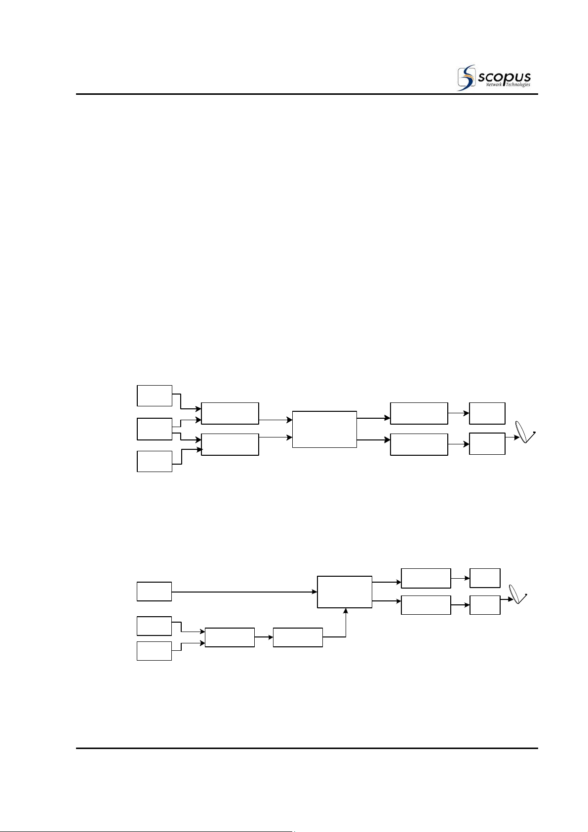
1.1.2.2. Dual Path DSNG Uplink Application
Figure 1-4 shows a typical dual path uplink (audio omitted for clarity), with an E-1000 and
an E-1710 cascaded to provide a combined Transport Stream feeding a single RF uplink
chain.
Figure 1-4: Dual Path DSNG Uplink Application
VTR
TV
CAMERA 1
TV
CAMERA 2
PRODUCTION
SWITCHER
Analog or SDI
E-1000 (SLAVE)
E-1710 COMPACT
DSNG ENCODER
Cascade
L-Band
IRD DECODER
IF
UP CONVERTER
L-Band
IF
70 MHZ - SHF
IRD DECODER
70 MHZ - SHF
UP CONVERTER
A/V
MONITOR
HPA
A/V
MONITOR
HPA
Pub. No. 1000401 Page 1-5
1.1.2.3. Triple Path DSNG Uplink Application
Figure 1-5 shows a typical triple path uplink (audio omitted for clarity), with two E-1000s
cascaded into to a single E-1710 to provide a combined Transport Stream feeding a single
RF uplink chain.
The E-1710 can be set to run in low-delay mode to give naturalistic Q&A responses in a
live ‘two-way’ update, while a tape can be run simultaneously in parallel to give the
station rushes of the news event as it’s happening. The external feed provides pictures
and audio from another source, e.g. an affiliate, covering the same event.
Figure 1-5: Triple Path DSNG Uplink Application
User Manual
Chapter 1. Overview
Analog
TV
CAMERA 1
VTR
TV
CAMERA 2
E-1000 (SLAVE 2)
or SDI
E-1000 (SLAVE 1)
Cascade
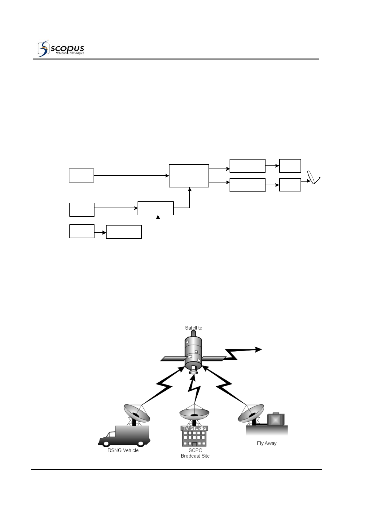
1.1.2.4. Input Encoding Capability
In addition to DSNG and Fly-Away capabilities, the E-1710 DSNG Encoder is ideally suited
for fixed earth station applications. As found in all E-1000 Series encoders, the E-1710
provides high-quality solutions for traditional applications that require the broadcast of a
single channel (SCPC) or multiple channels (MCPC), multiplexed and/or encrypted and
scrambled.
Figure 1-6 shows an illustration of the SCPC application.
Figure 1-6: E-1710 Compact DSNG Encoder in an SCPC application.
E-1710 COMPACT
DSNG ENCODER
Cascade
L-Band
IRD DECODER
IF
UP CONVERTER
70 MHZ - SHF
A/V
MONITOR
HPA
Page 1-6
Pub. No. 1000401
 Loading...