

! ! Version 1.00 LinkStar-STX3-ME
Users Manual!
Holland, Michigan — Rio Rancho, New Mexico
!
25!!
!
6 What%Makes%Your%Satellite%Transmitter%Tick?%The%Hardware%of%the%
LinkStar-STX3-ME/
!
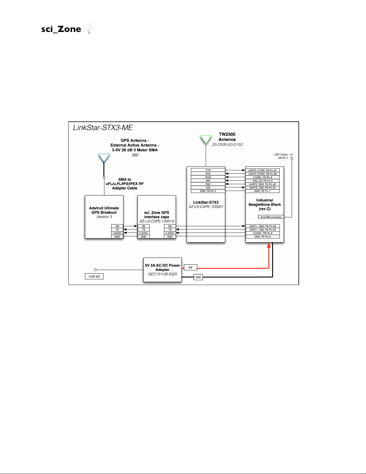
The basic elements of a design utilizing the LinkStar-STX3-ME simplex transmitter are shown in Figure 6
below.
Figure 6. The LinkStar-STX3-ME
The main components of the LinkStar-STX3-ME are:
• The Industrial BeagleBone Black (rev C)
• The LinkStar-STX3 satellite radio module
• TW2500 Antenna (for the LinkStar-STX3 satellite radio module)
• The sci_Zone GPS Interface cape
• The Adafruit Ultimate GPS Breakout
• GPS External Active Antenna with SMA to uFL/u.FL/IPX/IPEX RF adapter cable
• 5V 2A AC-DC Power Adapter

! ! Version 1.00 LinkStar-STX3-ME
Users Manual!
Holland, Michigan — Rio Rancho, New Mexico
!
26!!
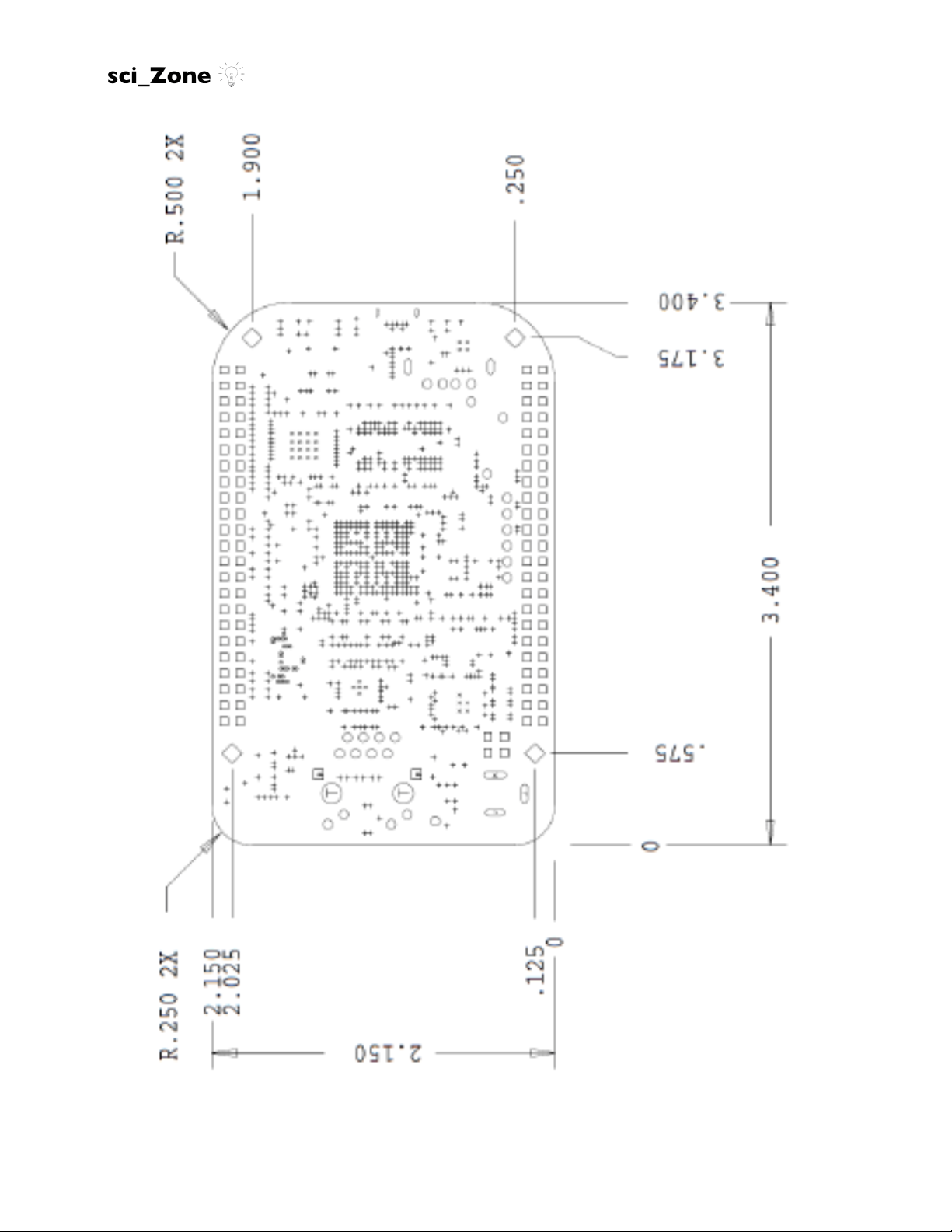
6.1 Mechanical/
Both the LinkStar-STX3 satellite radio module and the sci_Zone GPS Interface cape are
capes that stack on the Industrial BeagleBone Black headers. The dimensions and
mounting hole location of the Industrial BeagleBone Black are shown in Figure 7. The
entire system is mounted inside a “BUD Box”; Figure 8 shows the dimensions of the
case.
The antenna used for the LinkStar-STX3-ME is the Tallysman™ TW2500 magnetic
mount antenna with 50 cm cable with SMA male connector. Figure 9 shows the
dimensions of the TW2500 satellite radio antenna. For applications above 50,000 feet
the user is recommended to use the Tallysman™ TW1500 antenna which can be
ordered from sci_Zone.
The Adafruit Ultimate GPS Breakout dimensions can be found in Figure 10. This GPS
can be used for high altitude balloon applications to over 100,000 feet. For advanced
aviation and space applications of the LinkStar-STX3 the user is required to upgrade to
the NovAtel™ OEM 719 GPS which is sold by sci_Zone. Special certifications are
required to use the OEM 719 GPS in space and will require the permission of the U.S.
government.
The GPS External Active Antenna is a magnetic mount active antenna with 5m cable.
The dimensions can be found in Figure 11.
Size (circuit boards): 3.5” x 2.15” (86.36mm x 53.34mm)
Maximum Height (circuit boards):
Size (case): 6.632” x 4.764” x 3.158” (168.5mm x 121.0mm x 80.21mm)
Mass (with antennas):
! ! Version 1.00 LinkStar-STX3-ME
Users Manual!
Holland, Michigan — Rio Rancho, New Mexico
!
27!!
Figure 7. Industrial BeagleBone Black board dimensions.

! ! Version 1.00 LinkStar-STX3-ME
Users Manual!
Holland, Michigan — Rio Rancho, New Mexico
!
28!!
Figure 8. LinkStar-STX3-ME case (“BUD box”) dimensions.

! ! Version 1.00 LinkStar-STX3-ME
Users Manual!
Holland, Michigan — Rio Rancho, New Mexico
!
29!!
Figure 9. The TW2500 Satellite Radio Antenna Dimensions.
TW2500 Dimensions (mm)

! ! Version 1.00 LinkStar-STX3-ME
Users Manual!
Holland, Michigan — Rio Rancho, New Mexico
!
30!!
Figure 10. The Adafruit™ Ultimate GPS Breakout Dimensions.

! ! Version 1.00 LinkStar-STX3-ME
Users Manual!
Holland, Michigan — Rio Rancho, New Mexico
!
31!!
Figure 11. GPS External Active Antenna Dimensions.

! ! Version 1.00 LinkStar-STX3-ME
Users Manual!
Holland, Michigan — Rio Rancho, New Mexico
!
32!!
6.2 Electrical/
Power to the LinkStar-STX3-ME is provided through the 5V 2A AC-DC power adapter
connected to the 2.1mm female/male barrel jack connector cable which is connected to
the Industrial BeagleBone Black.
The Industrial BeagleBone Black provides power to the LinkStar-STX3 cape, the
Adafruit Ultimate GPS Breakout and the GPS External Active Antenna.
DO NOT PLUG IN THE USB CORD FIRST!
IF the USB cord is plugged in first to your computer it will provide power through it to the
Industrial BeagleBone Black and it will be the default power source for the LinkStarSTX3-ME. The power provided through the USB cord is insufficient to drive either the
LinkStar-STX3 satellite radio module or the Adafruit Ultimate GPS Breakout. YOUR
RADIO WILL BE UNABLE TO BROADCAST DATA PACKETS TO THE GLOBALSTAR
NETWORK!
Other sources of power CAN be provided to the LinkStar-STX3-ME including LithiumIon batteries and solar panels as long as the power requirements for the Industrial
BeagleBone Black are met AND at least 5V@1 amp are provided to the system. Refer
to the BeagleBone Black System Reference Manual (Rev C) for details on power
options for the BeagleBone Black.
If the Adafruit Ultimate GPS Breakout is disabled, disconnected from the sci_Zone GPS
Interface Cape, or power is removed the LinkStar-STX3-ME will not transmit packets to
the Globalstar network. Transmission only occurs when Adafruit GPS is connected via
the sci_Zone GPS Interface Cape and is powered on AND has verified a signal from the
GPS satellites in orbit AND has verified the location and altitude of the LinkStar-STX3-
ME. This allows the LinkStar-STX3-ME to set the appropriate channel based on location
and altitude, or block message transmission if the LinkStar-STX3-ME is in a restricted
area. If there is no GPS signal and if the location and altitude cannot be verified, the
LinkStar-STX3-ME shall not transmit a message. If the Adafruit GPS is disconnected,
inoperable, or damaged the LinkStar-STX3-ME will be unable to transmit any
messages.
!
!
!
!
!

! ! Version 1.00 LinkStar-STX3-ME
Users Manual!
Holland, Michigan — Rio Rancho, New Mexico
!
33!!
!
6.3 Environmental%
!
Operating Temperature Range: -40 to +85 ºC
Vibration, TW2500 Antenna: 3 axis, sweep=15 min, 10 to 200Hz sweep: 3G
Shock, TW2500 Antenna: Vertical axis: 50 G, other axes: 30 G
6.4 Pins%Used%On%The%Industrial/BeagleBone/Bla c k/
!
The following pins are used by the LinkStar-STX3-ME and NOT AVAILABLE FOR USE
BY ANY DEVICE:
HEADER P8
P7: TIMER4
P8: TIMER7
P9: TIMER5
P10: TIMER6
P11: GPIO1_13
P12: GPIO1_12
P14: GPIO0_26
P31: UART5_CTSN
P32: UART5_RTSN
P37: UART2_CTSN
P38: UART2_RTSN
HEADER P9
P3: DC_3.3V
P4: DC_3.3V
P5: VDD_5V
P21: UART2-TXD
P22: UART2-RXD
P24: UART1_TXD
P26: UART1_RXD
 Loading...