

Scitec 410 User Manual

MODEL 410 ANALOGUE SINGLE PHASE
LOCK-IN AMPLIFIER
USER MANUAL
Issue 2.6

410 Manual Issue 2-5
2
Unit 6 Sandown Centre
White Horse Business Park
Trowbridge
BA14 0XD
United Kingdom
t. +44 [0]1225 751 542
i. www.scitec.uk.com
e. sales@scitec.uk.com
Director. JW Smith Ph.D
Scitec Instruments Ltd
Registered in England
No. 1535664
Registered Office
Scitec Instruments Ltd
Unit 6 Sandown Centre
White Horse Business Park
Trowbridge
BA14 0XD
United Kingdom
CONTENTS
1.1
WARNING
1.2
Power Supply
1.3
To Change The Voltage Selection Switch
1.4
Earth
1.5
Fuse
2
OPERATION
3
INPUT STAGE
3.1
Accessing Input Stage Jumpers
3.2
Jumper Settings Overview
3.3
Single Ended DC Coupled Input (Default Setting)
3.4
Single Ended AC Coupled Input
3.5
Single Ended Current Input
3.6
Differential Input
3.7
Low Impedance Differential Input
4
SIGNAL GROUND, CASE GROUND AND EARTH
4.1
Accessing Input Stage Jumpers
4.2
Signal Ground Connected to Case and Electrical Earth (Default Setting)
4.3
Signal Ground Connected to Case and Electrical Earth Via 100W Resistor
4.4
Signal Ground Isolated From Case and Electrical Earth
5
REFERENCE SECTION
5.1
1F/2F Reference Select Switch
5.2
Coarse Phase Control
5.3
Fine Phase Control
6
DEMODULATOR / OUTPUT SECTION
7
HOW TO MAKE QUICK MEASUREMENTS
8
HOW TO MAKE ACCURATE MEASUREMENTS
410 Manual Issue 2-5
3
Unit 6 Sandown Centre
White Horse Business Park
Trowbridge
BA14 0XD
United Kingdom
t. +44 [0]1225 751 542
i. www.scitec.uk.com
e. sales@scitec.uk.com
Director. JW Smith Ph.D
Scitec Instruments Ltd
Registered in England
No. 1535664
Registered Office
Scitec Instruments Ltd
Unit 6 Sandown Centre
White Horse Business Park
Trowbridge
BA14 0XD
United Kingdom
POWER SUPPLY
1.1 WARNING
This instrument can be damaged if operated with
the mains voltage selector incorrectly set.
Switch off and disconnect mains power before
opening unit. Do not operate the unit with the lid
removed as there are mains voltages within the
unit.
1.2 Power Supply
The unit will accept either: or:
115V AC ±5% at 50Hz or 60Hz 230V AC ±5% at 50Hz or 60Hz
The voltage selection switch is mounted inside the unit. The current voltage
selection is marked on the label on the back of the unit.
1.3 To Change The Voltage Selection Switch
1) Switch off and disconnect mains power before opening unit.
2) Remove the 10 screws holding the lid on then remove lid. Do not
disconnect earth strap.
3) Change the voltage selection switch mounted on the PCB to the rear of
the unit next to the transformer (large blue box). Available settings are
115V and 230V.
4) Replace lid and the 10 screws.
Update the label on the back of the unit to indicate the current voltage
selection switch position. It is very important that this is done to ensure
there is no confusion in the future.
1.4 Earth
The instrument should be earthed via the mains
inlet cable. The instrument is encased in a metal
box, which is connected to this earth. No
modifications should be made to this earthing
mechanism. Without this earth connection it is
possible for the box to become live under fault
conditions. The signal ground can however be
disconnected, for details see section 4.
1.5 Fuse
The unit is fitted with a 1Amp anti-surge (T) 5x20mm fuse, incorporated into
the mains connector on the rear of the unit.
Only replace the fuse with another of the same type, size and value.
To access the fuse, first remove the mains cable then open the fuse
compartment with a finger nail. When shipped from the factory the fuse
compartment contains two fuses. The inside fuse is the fuse in use, whilst
the outside fuse is a spare and can be used to replace the inside fuse if it is
blown.

410 Manual Issue 2-5
4
Unit 6 Sandown Centre
White Horse Business Park
Trowbridge
BA14 0XD
United Kingdom
t. +44 [0]1225 751 542
i. www.scitec.uk.com
e. sales@scitec.uk.com
Director. JW Smith Ph.D
Scitec Instruments Ltd
Registered in England
No. 1535664
Registered Office
Scitec Instruments Ltd
Unit 6 Sandown Centre
White Horse Business Park
Trowbridge
BA14 0XD
United Kingdom
2 OPERATION
After first ensuring that the current voltage selection is appropriate to your
mains supply, the mains lead can be connected to the rear of the unit. The
power supply switch (14)1 is mounted on the front panel and causes the
power on indicator to light (13).
Please note that the instrument has a number of circuits within it that require
time to settle on power up. This can cause the output meter to jump to full
scale for a short time on power up. This is most noticeable if the time
constant control (3) is set to a high value (above 1S). To speed up the
settling process turn the time constant control (3) to 1S or below.
If there is no reference signal connected to the unit then the offset nulling
circuitry within the unit does not operate and hence an offset may be seen
on the output. This is normal and will be removed when a reference signal is
applied.
It is safe to apply signals to the unit whilst the lock-in is switched off, though
this is not recommended for any length of time. However, the input
impedance of the signal input and reference input with unit switched off may
drop producing an unacceptable load on the sources of these signals. It is
hence recommended that the unit is switched on whenever input signals are
applied to it.
Care should be made that the reference signal does not affect the input
signal. The reference signal is commonly many factors larger than the signal
to be measured and it is therefore relatively easy for the reference signal to
be picked up on input signal cable. For this reason keep the cabling for the
input signal as far away as possible from the cabling for the reference signal.
Careful screening helps but it is still possible for the input cable to pick up
the reference signal if significant lengths are put into close contact.
1
The numbers in brackets refer to the numbers used in Figure 17 at the back of this manual.
410 Manual Issue 2-5
5
Unit 6 Sandown Centre
White Horse Business Park
Trowbridge
BA14 0XD
United Kingdom
t. +44 [0]1225 751 542
i. www.scitec.uk.com
e. sales@scitec.uk.com
Director. JW Smith Ph.D
Scitec Instruments Ltd
Registered in England
No. 1535664
Registered Office
Scitec Instruments Ltd
Unit 6 Sandown Centre
White Horse Business Park
Trowbridge
BA14 0XD
United Kingdom
3 INPUT STAGE
The input stage amplifies the input signal to a level suitable for demodulator
section.
The input signal should be connected to the BNC signal input connector (2).
The input sensitivity is set by using the input sensitivity dial (1). Please note
that it is not possible to rotate the dial directly from the 1V setting to the 3µV
setting.
The input stage of the unit can operate in a number of ways. By default, the
unit is factory set so the input stage acts as a single ended, DC coupled
input as this is the lowest noise method of operation. It is also possible to
operate the input stage in AC coupled mode, differential mode and current
mode. To operate the lock-in in these different modes requires jumpers
within the unit to be modified. This can be achieved as follows:
3.1 Accessing Input Stage Jumpers
1) The input stage includes jumpers which enable the mode of operation
of the input stage to be modified. To access the jumpers:
2) Switch off and disconnect mains power before opening unit.
3) Remove the 10 screws holding the lid on then remove lid. Do not
disconnect earth strap.
4) Change the jumper settings as per the diagrams in the following
sections. Do not operate the unit with the lid removed due to the mains
voltages accessible within the unit.
5) Replace lid and the 10 screws.
3.2 Jumper Settings Overview
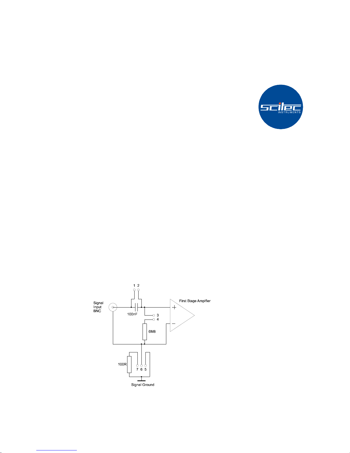
A simplified input stage circuit diagram is shown in Figure 1. This shows all
of the jumpers in the input stage.
Figure 1 - Input Stage Jumper Options
410 Manual Issue 2-5
6
Unit 6 Sandown Centre
White Horse Business Park
Trowbridge
BA14 0XD
United Kingdom
t. +44 [0]1225 751 542
i. www.scitec.uk.com
e. sales@scitec.uk.com
Director. JW Smith Ph.D
Scitec Instruments Ltd
Registered in England
No. 1535664
Registered Office
Scitec Instruments Ltd
Unit 6 Sandown Centre
White Horse Business Park
Trowbridge
BA14 0XD
United Kingdom
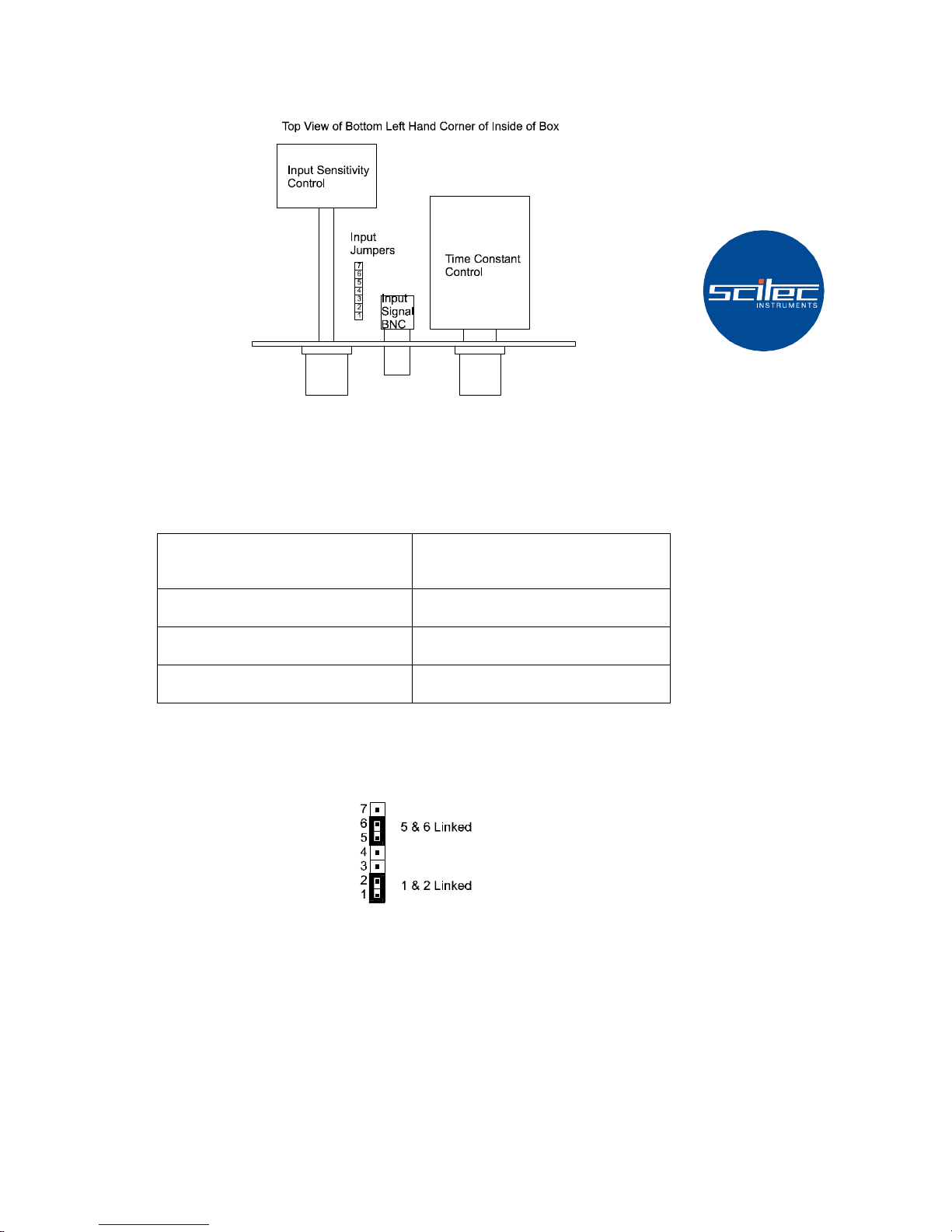
A diagram of the position of the input stage jumpers is shown in Figure 2.
Figure 2 - Input Stage Jumper Positions
3.3 Single Ended DC Coupled Input (Default Setting)
The default setting is for a single ended DC coupled input. This mode gives
the best noise performance. Although the input is DC coupled, the input will
not saturate with up to the following DC offsets on the input:
Input Gain Setting
Maximum DC Input Offset Before
Saturation Occurs
1V to 3mV ±10V
1mV to 30µV ±1V
10µV to 3µV ±100mV
The input impedance of the lock-in in this mode is 1012Ω ||1nF.
The jumper settings for this mode are given in Figure 3. The equivalent
circuit is shown in Figure 4.
Figure 3 - Single Ended DC Coupled Input Settings
 Loading...