


SMARTMAG
MODELS SM–4/4G
OPERATIONS MANUAL

SCINTREX LIMITED
Head Office In the U.S.A. In Australia
222 Snidercroft Road
Concord, Ontario
Canada, L4K 1B5
Tel.: (905) 669-2280
Fax: (905) 669-6403 (Sales)
(905) 669-9899 (Service)
Telex: 06-964570
Copyright © SCINTREX Limited 1996. All rights reserved.
No part of this publication may be reproduced, stored in a retrieval
system or transmitted, in any form, or by any means, electronic,
mechanical, photo-copying, recording, or otherwise, without prior
consent from SCINTREX Limited.
SMARTMAG and WALKMAG are trademarks of SCINTREX Limited.
525 Fort Worth Drive
Suite 216
Denton, Texas 76201
Tel.: (817) 591-7755
Fax: (817) 591-1968
1031 Wellington St.
West Per t h ,
West Australia 6005
Tel: (619) 321-6934
Fax: (619) 481-1201
Document P/N 759 704
Revision 1.0
Manual designed and produced by GEO F/X.
Printed and bound in Canada.

Disclaimer
Preface
Features . . . . . . . . . . . . . . . . . . . . . . . . . . . . . . . . . . . . . . . xi
SMARTMAG versions. . . . . . . . . . . . . . . . . . . . . . . . . . . . . xii
About This Manual . . . . . . . . . . . . . . . . . . . . . . . . . . . . . . . xv
Type styles . . . . . . . . . . . . . . . . . . . . . . . . . . . . . . . . . . xv
Page numbering . . . . . . . . . . . . . . . . . . . . . . . . . . . . . . xv
Symbols . . . . . . . . . . . . . . . . . . . . . . . . . . . . . . . . . . . . . . . xvi
HELP-Line . . . . . . . . . . . . . . . . . . . . . . . . . . . . . . . . . . . . . xvii
1–Introduction
Cold boot . . . . . . . . . . . . . . . . . . . . . . . . . . . . . . . . . . . . . . . 1–2
Instrument overview . . . . . . . . . . . . . . . . . . . . . . . . . . . . . . 1–3
SMARTMAG
Table of Contents
Table of Contents
2–Preparing the SMARTMAG
Unpacking . . . . . . . . . . . . . . . . . . . . . . . . . . . . . . . . . . . . . . 2–2
Repacking . . . . . . . . . . . . . . . . . . . . . . . . . . . . . . . . . . . . . . 2–2
Assembly . . . . . . . . . . . . . . . . . . . . . . . . . . . . . . . . . . . . . . . 2–3
Installing the battery belt . . . . . . . . . . . . . . . . . . . . . . . . 2–3
Installing/exchanging the battery in the battery belt. . . . . . 2–4
Connecting the sensor(s) to the Battery Belt . . . . . . . . . . 2–4
Installing the LED display and keyboard . . . . . . . . . . . . . . . 2–5
Installing the shoulder strap . . . . . . . . . . . . . . . . . . . . . . 2–6
Installing the audio option kit . . . . . . . . . . . . . . . . . . . . . . 2–6
SMARTMAG console battery installation/exchange . . . . . . . 2–7
Using the external battery pack . . . . . . . . . . . . . . . . . . . . 2–8
Using an external power supply . . . . . . . . . . . . . . . . . . . . 2–10
i

3–Guidelines
Operator preparation . . . . . . . . . . . . . . . . . . . . . . . . . . . . . 3–1
Geometry of dead zones . . . . . . . . . . . . . . . . . . . . . . . . . . . 3–1
Determining operating zones . . . . . . . . . . . . . . . . . . . . . . . 3–3
Adjusting the sensor head angle. . . . . . . . . . . . . . . . . . . . . 3–4
4–The SMARTMAG Model SM–4
Receiving your instrument . . . . . . . . . . . . . . . . . . . . . . . . . 4–1
The components . . . . . . . . . . . . . . . . . . . . . . . . . . . . . . . . . 4–2
Assembling the instrument . . . . . . . . . . . . . . . . . . . . . . . 4–2
Connecting the cables. . . . . . . . . . . . . . . . . . . . . . . . . . . 4–2
Setting up the instrument . . . . . . . . . . . . . . . . . . . . . . . . . 4–3
Turning on the instrument . . . . . . . . . . . . . . . . . . . . . . . . 4–3
Using the headphones. . . . . . . . . . . . . . . . . . . . . . . . . . . 4–4
Setting the parameters with the console . . . . . . . . . . . . . 4–4
Using the LED display and keypad . . . . . . . . . . . . . . . . . . . . 4–5
Keypad . . . . . . . . . . . . . . . . . . . . . . . . . . . . . . . . . . . . . 4–5
Displays and Functions . . . . . . . . . . . . . . . . . . . . . . . . . . 4–5
Performing a Survey . . . . . . . . . . . . . . . . . . . . . . . . . . . . . . 4–8
5–The SMARTMAG Model SM–4G
Receiving your instrument . . . . . . . . . . . . . . . . . . . . . . . . . 5–1
The components . . . . . . . . . . . . . . . . . . . . . . . . . . . . . . . . . 5–2
Assembling the instrument . . . . . . . . . . . . . . . . . . . . . . . . 5–2
Master processor . . . . . . . . . . . . . . . . . . . . . . . . . . . . . 5–2
Connecting the cables. . . . . . . . . . . . . . . . . . . . . . . . . . . 5–3
Setting up the instrument . . . . . . . . . . . . . . . . . . . . . . . . . 5–4
Turning on the instrument . . . . . . . . . . . . . . . . . . . . . . . . 5–4
Using the headphones. . . . . . . . . . . . . . . . . . . . . . . . . . . 5–4
Setting the parameters with the SMARTMAG console . . . 5–5
Using the LED display and keypad . . . . . . . . . . . . . . . . . . . . 5–5
Keypad . . . . . . . . . . . . . . . . . . . . . . . . . . . . . . . . . . . . . 5–6
Displays and Functions . . . . . . . . . . . . . . . . . . . . . . . . . . 5–6
Assembling the Gradiometer . . . . . . . . . . . . . . . . . . . . . . 5–9
Vertical Gradiometer . . . . . . . . . . . . . . . . . . . . . . 5–9
Horizontal Gradiometer . . . . . . . . . . . . . . . . . . . . 5–10
Performing a Survey . . . . . . . . . . . . . . . . . . . . . . . . . . . . . . 5–10
ii

6–The SMARTMAG Console
Pre-defined operating modes. . . . . . . . . . . . . . . . . . . . . . . . 6–1
Console description . . . . . . . . . . . . . . . . . . . . . . . . . . . . . . . 6–3
Keypad description . . . . . . . . . . . . . . . . . . . . . . . . . . . . . . . 6–4
Key Functions . . . . . . . . . . . . . . . . . . . . . . . . . . . . . . . . . 6–5
Display screens . . . . . . . . . . . . . . . . . . . . . . . . . . . . . . . . . . 6–8
General information. . . . . . . . . . . . . . . . . . . . . . . . . . . . . 6–8
Cursor . . . . . . . . . . . . . . . . . . . . . . . . . . . . . . . . 6–9
Display blocks . . . . . . . . . . . . . . . . . . . . . . . . . . . 6–9
Pop-up windows . . . . . . . . . . . . . . . . . . . . . . . . . . 6–10
Help screens . . . . . . . . . . . . . . . . . . . . . . . . . . . . 6–11
Operating displays. . . . . . . . . . . . . . . . . . . . . . . . . . . . . . . . 6–12
Basic mode configuration displays . . . . . . . . . . . . . . . . . . 6–12
Basic mode data collection displays . . . . . . . . . . . . 6–16
Search mode configuration display . . . . . . . . . . . . . . . . . . 6–17
Search mode data collection displays . . . . . . . . . . . 6–19
Advanced mode configuration displays. . . . . . . . . . . . . . . . 6–20
Main operating display . . . . . . . . . . . . . . . . . . . . . 6–20
Instrument setup display . . . . . . . . . . . . . . . . . . . 6–22
Magnetometer setup display . . . . . . . . . . . . . . . . . 6–23
Advanced mode data displays . . . . . . . . . . . . . . . . . . . . . . 6–26
Numeric data display . . . . . . . . . . . . . . . . . . . . . . 6–26
Graphic data display . . . . . . . . . . . . . . . . . . . . . . . 6–28
Recall displays . . . . . . . . . . . . . . . . . . . . . . . . . . . . . . . . 6–29
Recall setup display . . . . . . . . . . . . . . . . . . . . . . . 6–29
Recall data display . . . . . . . . . . . . . . . . . . . . . . . . 6–30
Modifying the display window . . . . . . . . . . . . . . . . . 6–32
Auxiliary display. . . . . . . . . . . . . . . . . . . . . . . . . . . . . . . . 6–33
Data output display. . . . . . . . . . . . . . . . . . . . . . . . . . . . . 6–34
Data output formats . . . . . . . . . . . . . . . . . . . . . . 6–36
Notes display . . . . . . . . . . . . . . . . . . . . . . . . . . . . . . . . . 6–37
Information display . . . . . . . . . . . . . . . . . . . . . . . . . . . . . 6–38
SMARTMAG Distance Trigger . . . . . . . . . . . . . . . . . . . . . . . 6–39
Table of Contents
7–Setting-up the SMARTMAG Console
First time operation . . . . . . . . . . . . . . . . . . . . . . . . . . . . . . 7–1
Cold Boot . . . . . . . . . . . . . . . . . . . . . . . . . . . . . . . . . . . . 7–2
Configuration menu . . . . . . . . . . . . . . . . . . . . . . . . . . . . . 7–3
General setup principles . . . . . . . . . . . . . . . . . . . . . . . . . . . 7–4
iii

How to: . . . . . . . . . . . . . . . . . . . . . . . . . . . . . . . . . . . . . . . . 7–5
Access the main operating display . . . . . . . . . . . . . . . . . . 7–5
Access display sub-panels/blocks . . . . . . . . . . . . . . . . . . . 7–5
Access the parameter fields . . . . . . . . . . . . . . . . . . . . . . 7–5
Change parameters . . . . . . . . . . . . . . . . . . . . . . . . . . . . 7–5
Select! and Enter!. . . . . . . . . . . . . . . . . . . . . . . . . . . . . . 7–6
Select! . . . . . . . . . . . . . . . . . . . . . . . . . . . . . . . . 7–6
Enter! . . . . . . . . . . . . . . . . . . . . . . . . . . . . . . . . . 7–6
Line and Station setup . . . . . . . . . . . . . . . . . . . . . . . . . . . . 7–7
Entering the starting station . . . . . . . . . . . . . . . . . . . . . 7–8
Entering the starting line . . . . . . . . . . . . . . . . . . . . . . . . 7–8
Basic Mode . . . . . . . . . . . . . . . . . . . . . . . . . . . . . . . . . . . . . 7–9
Sample total-field setup . . . . . . . . . . . . . . . . . . . . . . . . . 7–9
Starting Your Survey . . . . . . . . . . . . . . . . . . . . . . . . . . . 7–11
Search Mode. . . . . . . . . . . . . . . . . . . . . . . . . . . . . . . . . . . . 7–12
Sample search mode setup . . . . . . . . . . . . . . . . . . . . . . . 7–12
Advanced Mode . . . . . . . . . . . . . . . . . . . . . . . . . . . . . . . . . . 7–14
Instrument setup . . . . . . . . . . . . . . . . . . . . . . . . . . . . . . 7–14
Sample total-field setup (WALKMAG or WALKGRAD) . . . . . 7–15
Sample base-station setup . . . . . . . . . . . . . . . . . . . . . . . 7–18
Information display . . . . . . . . . . . . . . . . . . . . . . . . . . . . . 7–21
Note entry. . . . . . . . . . . . . . . . . . . . . . . . . . . . . . . . . . . 7–23
Display intensity control . . . . . . . . . . . . . . . . . . . . . . . . . 7–25
Parameter lock. . . . . . . . . . . . . . . . . . . . . . . . . . . . . . . . 7–26
Reprogramming the operating system . . . . . . . . . . . . . . . 7–27
At the computer . . . . . . . . . . . . . . . . . . . . . . . . . 7–27
At the SMARTMAG Console . . . . . . . . . . . . . . . . . 7–27
8–Operating the SMARTMAG with the Console
Accurate and meaningful measurements . . . . . . . . . . . . . . 8–1
Determining operating zones . . . . . . . . . . . . . . . . . . . . . . 8–2
Effects of gradient . . . . . . . . . . . . . . . . . . . . . . . . . . . . . 8–2
Other sources of noise . . . . . . . . . . . . . . . . . . . . . . . . . . 8–2
Base-station . . . . . . . . . . . . . . . . . . . . . . . . . . . . . . . . . 8–3
Repeated surveys lines . . . . . . . . . . . . . . . . . . . . . . . . . . . . 8–3
WALKMAG—Total-field/Gradiometer . . . . . . . . . . . . . . . . . . 8–4
Check your setup . . . . . . . . . . . . . . . . . . . . . . . . . . . . . . 8–5
Start survey . . . . . . . . . . . . . . . . . . . . . . . . . . . . . . . . . 8–5
WALKGRAD gradiometer survey . . . . . . . . . . . . . . . . . . . 8–6
iv

Manual mode—Total-field/Gradiometer . . . . . . . . . . . . . . . . 8–7
Check your setup . . . . . . . . . . . . . . . . . . . . . . . . . . . . . . 8–8
Start survey. . . . . . . . . . . . . . . . . . . . . . . . . . . . . . . . . . 8–8
Automating your measurements . . . . . . . . . . . . . . . . . . . 8–9
Base-station operation . . . . . . . . . . . . . . . . . . . . . . . . . . . . 8–10
Check your setup . . . . . . . . . . . . . . . . . . . . . . . . . . . . . . 8–11
Start operation . . . . . . . . . . . . . . . . . . . . . . . . . . . . . . . 8–11
Search mode . . . . . . . . . . . . . . . . . . . . . . . . . . . . . . . . . . . . 8–12
Basic . . . . . . . . . . . . . . . . . . . . . . . . . . . . . . . . . . . . . . . 8–12
Advanced . . . . . . . . . . . . . . . . . . . . . . . . . . . . . . . . . . . . 8–13
Survey data correction procedures. . . . . . . . . . . . . . . . . . . 8–14
Using base-station data . . . . . . . . . . . . . . . . . . . . . . . . . 8–14
Tie-point (TIE-PT) mode . . . . . . . . . . . . . . . . . . . . . . . . . . 8–15
Loop type—collecting data . . . . . . . . . . . . . . . . . . 8–15
Line type—collecting data. . . . . . . . . . . . . . . . . . . 8–16
Tie-point correction procedure . . . . . . . . . . . . . . . . . . . . . 8–18
Basic modes (Loop only) . . . . . . . . . . . . . . . . . . . . 8–18
Advanced modes . . . . . . . . . . . . . . . . . . . . . . . . . 8–19
9–Data output
Output formats . . . . . . . . . . . . . . . . . . . . . . . . . . . . . . . . . . 9–1
XYZ . . . . . . . . . . . . . . . . . . . . . . . . . . . . . . . . . . . . . . . . 9–2
XYZ+ . . . . . . . . . . . . . . . . . . . . . . . . . . . . . . . . . . . . . . . 9–3
XYZ++ . . . . . . . . . . . . . . . . . . . . . . . . . . . . . . . . . . . . . 9–4
PRN. . . . . . . . . . . . . . . . . . . . . . . . . . . . . . . . . . . . . . . . 9–5
NOTES . . . . . . . . . . . . . . . . . . . . . . . . . . . . . . . . . . . . . . 9–6
BINARY . . . . . . . . . . . . . . . . . . . . . . . . . . . . . . . . . . . . . 9–7
Converting binary data with XFSMART . . . . . . . . . . 9–7
Basic mode . . . . . . . . . . . . . . . . . . . . . . . . . . . . . . . . . . . . . 9–9
Advanced mode . . . . . . . . . . . . . . . . . . . . . . . . . . . . . . . . . . 9–10
Output setup . . . . . . . . . . . . . . . . . . . . . . . . . . . . . . . . . 9–10
Dumping data . . . . . . . . . . . . . . . . . . . . . . . . . . . . . . . . . 9–12
All data . . . . . . . . . . . . . . . . . . . . . . . . . . . . . . . . 9–12
Specific data . . . . . . . . . . . . . . . . . . . . . . . . . . . . 9–13
Binary Dump . . . . . . . . . . . . . . . . . . . . . . . . . . . . 9–13
Line by line. . . . . . . . . . . . . . . . . . . . . . . . . . . . . . 9–14
Erasing data from memory. . . . . . . . . . . . . . . . . . . . . . . . 9–15
Basic mode . . . . . . . . . . . . . . . . . . . . . . . . . . . . . 9–15
Advanced mode . . . . . . . . . . . . . . . . . . . . . . . . . . 9–16
Table of Contents
v

10–Maintaining your SM–4/4G
General rules. . . . . . . . . . . . . . . . . . . . . . . . . . . . . . . . . . . 10–1
Charging the battery belt batteries . . . . . . . . . . . . . . . . . 10–2
Console battery charging . . . . . . . . . . . . . . . . . . . . . . . . . 10–3
One battery . . . . . . . . . . . . . . . . . . . . . . . . . . . . . . . . . 10–4
Two batteries . . . . . . . . . . . . . . . . . . . . . . . . . . . . . . . . 10–5
Periodic maintenance . . . . . . . . . . . . . . . . . . . . . . . . . . . . 10–6
Desiccant exchange . . . . . . . . . . . . . . . . . . . . . . . . . . . 10–6
Fuse replacement . . . . . . . . . . . . . . . . . . . . . . . . . . . . . . . 10–7
Console disassembly/assembly . . . . . . . . . . . . . . . . . . . . . 10–8
Cable repair. . . . . . . . . . . . . . . . . . . . . . . . . . . . . . . . . . . . 10–9
Sensor troubleshooting guide . . . . . . . . . . . . . . . . . . . . . . 10–10
Console troubleshooting guide . . . . . . . . . . . . . . . . . . . . . 10–11
11–Reference information
SMARTMAG Technical Specifications . . . . . . . . . . . . . . . . 11–1
Options . . . . . . . . . . . . . . . . . . . . . . . . . . . . . . . . . . . . 11–3
Instrument parts list . . . . . . . . . . . . . . . . . . . . . . . . . . . . 11–4
Warranty & Repair . . . . . . . . . . . . . . . . . . . . . . . . . . . . . . 11–5
Warranty . . . . . . . . . . . . . . . . . . . . . . . . . . . . . . . . . . . 11–5
Repair . . . . . . . . . . . . . . . . . . . . . . . . . . . . . . . . . . . . . 11–5
When to ship the unit . . . . . . . . . . . . . . . . . . . . 11–5
Description of the problem . . . . . . . . . . . . . . . . . 11–5
Shipping instructions . . . . . . . . . . . . . . . . . . . . . . . . . . 11–6
Customs documents . . . . . . . . . . . . . . . . . . . . . 11–7
A–Orienting Cesium sensors for best performance
Introduction . . . . . . . . . . . . . . . . . . . . . . . . . . . . . . . . . . . . A–1
The active zone of the SMARTMAG. . . . . . . . . . . . . . . . . . . A–2
Calculation of the tumble angle. . . . . . . . . . . . . . . . . . . . . . A–5
Recommended sensor orientations. . . . . . . . . . . . . . . . . . . A–14
vi

DISCLAIMER
The product supplied by the vendor under this sale agreement, when
properly maintained, calibrated and operated will perform in accor-
dance with the vendor’s published specifications. The vendor disclaims
responsibility for the detection of any particular target under any par-
ticular set of circumstances, and the purchaser and or user hereby ac-
knowledges and accepts such a disclaimer.
The purchase and or user releases and agrees to hold harmless the ven-
dor, its officers, servants, employees, agents and contractors, against
any and all claims, demands, actions and liabilities whatsoever, arising
out of the use or operation of the product.
SMARTMAG
Disclaimer
It is understood and agreed that this contract shall be governed by the
laws of the Province of Ontario, Canada.
vii

Disclaimer
viii

PREFACE
SMARTMAG
Preface
Congratulations on purchasing the SMARTMAG high sensitivity, high
resolution, cesium vapour magnetometer/gradiometer from
Ltd.! You are in possession of one of the most advanced magnetometers
for environmental, geotechnical, archaeological and mineral explora-
tion uses of today.
The
SMARTMAG is a portable, cesium magnetometer that also is inex-
pensive, lightweight and rugged. In its trademarked
it is ideal for applications where high production, fast reading and high
sensitivity are required.
WALKMAG mode,
SCINTREX
Preface
Your SM–4 is quite versatile and can be optionally upgraded and
configured as a gradiometer or as a base-station. To upgrade your sys-
tem to the SM–4G model, please contact your SCINTREX representative.
FEATURES
SMARTMAG The main features/options of the SMARTMAG include:
▲ integrated sensor/staff and processing electronics
▲ advanced digital signal processing for low noise 0.01nT
resolution
▲ rugged, waterproof design incorporating adjustable sensor head
▲ audio output with auto baseline tracking
▲ sunlight readable LED display and keypad
▲ RS-232/RS-422 output
▲ SMARTMAG console
ix
Preface
Console The main features of the SMARTMAG console include:
▲ real-time graphic display of magnetic field readings
▲ interactive menus for easy operator use
▲ selectable sampling rates as fast as 10 times per second
▲ WALKMAG mode for rapid data acquisition
▲ true simultaneous gradiometer option with the WALKGRAD mode
for rapid data acquisition
▲ large internal memory, expandable to over 300,000 readings
(750,000 for base station)
▲ easy to read, large LCD screen that displays data both graphically
and numerically
▲ easy review of the data and Datacheck quality control
▲ ENVIMAP software for processing and mapping of the data
SMARTMAG VERSIONS
There are five versions (factory configured) of the SMARTMAG:
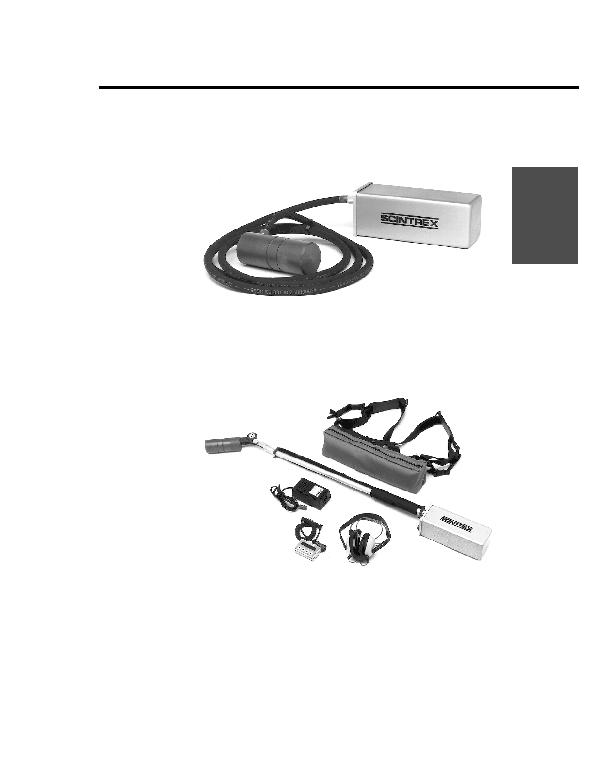
1. SMARTMAG model SM-1 (759 001):
Figure A SMARTMAG model SM-1 components
x
SMARTMAG versions
2. SMARTMAG model SM-2 (759 005):
Figure B SMARTMAG model SM-2 components
3. SMARTMAG model SM-3 (759 002):
Preface
Figure C SMARTMAG model SM-3 components
xi
Preface
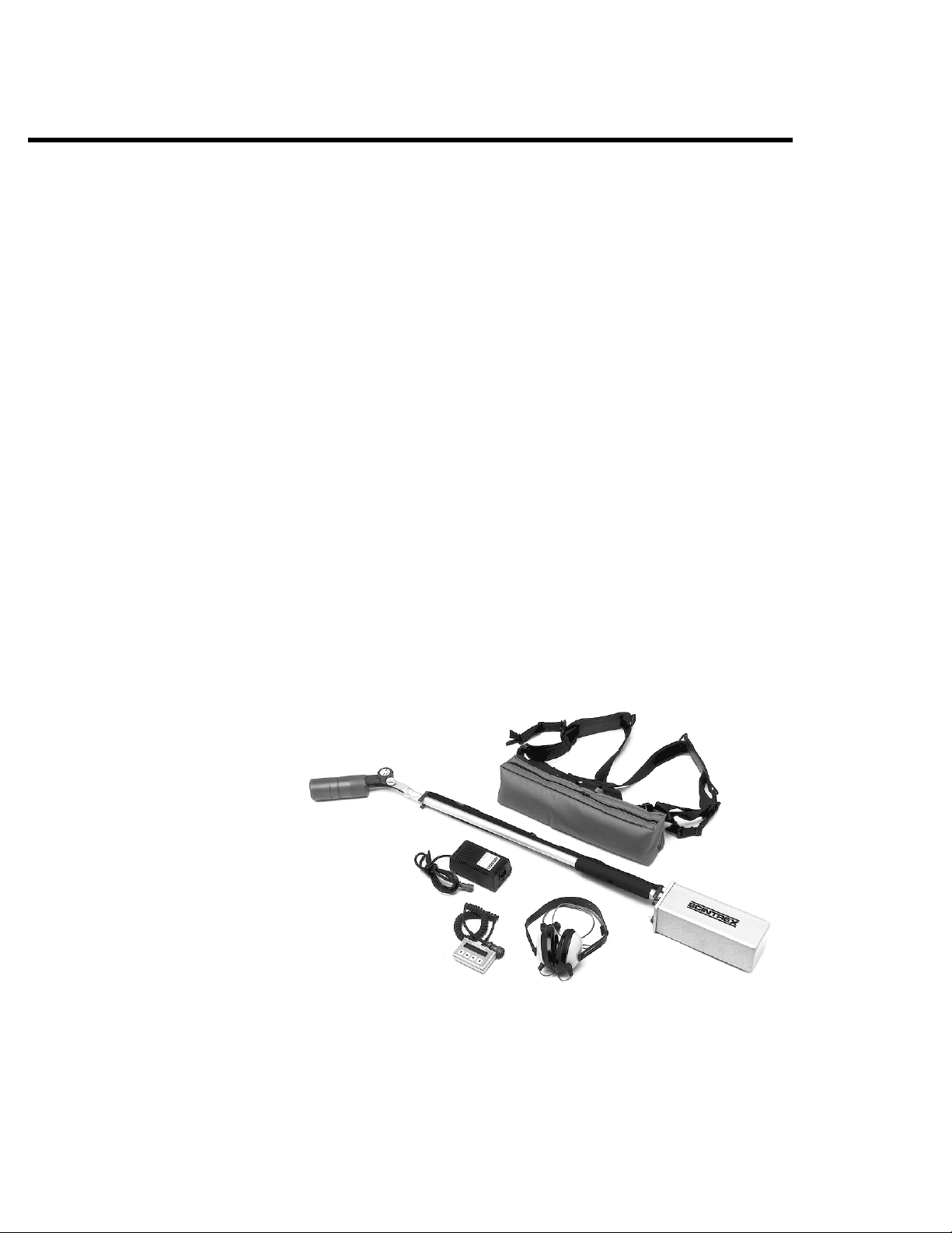
4. SMARTMAG model SM-4 (759 003):
Figure D SMARTMAG model SM-4 components
xii
5. SMARTMAG model SM-4G (759 004):
Figure E SMARTMAG model SM-4G components

ABOUT THIS MANUAL
About This Manual
TYPE STYLES
The following typeface conventions will be used throughout the man-
ual. There may be additional conventions used in the specific sections.
These will be described in the introduction for the section.
PAGE NUMBERING
Convention Use
Bold An action you are required to perform
A proper name.
Italic A new term is being introduced
An item of importance is being emphasized.
Dot Matrix A prompt on the
Text to be input to the console.
LED
ALL CAPS
A prompt or parameter on the LED display.
A display or key on the SMARTMAG console
The name of a method, item or mode.
SMARTMAG console
Preface
SYMBOLS
The page numbering scheme used consists of two parts; the chapter
number and page number. For exa mple,
page 1.
For your convenience, each chapter in a section has a thumb-tab on the
right-hand side allowing you to quickly locate a chapter of interest. The
thumb-tabs are arranged in descending order.
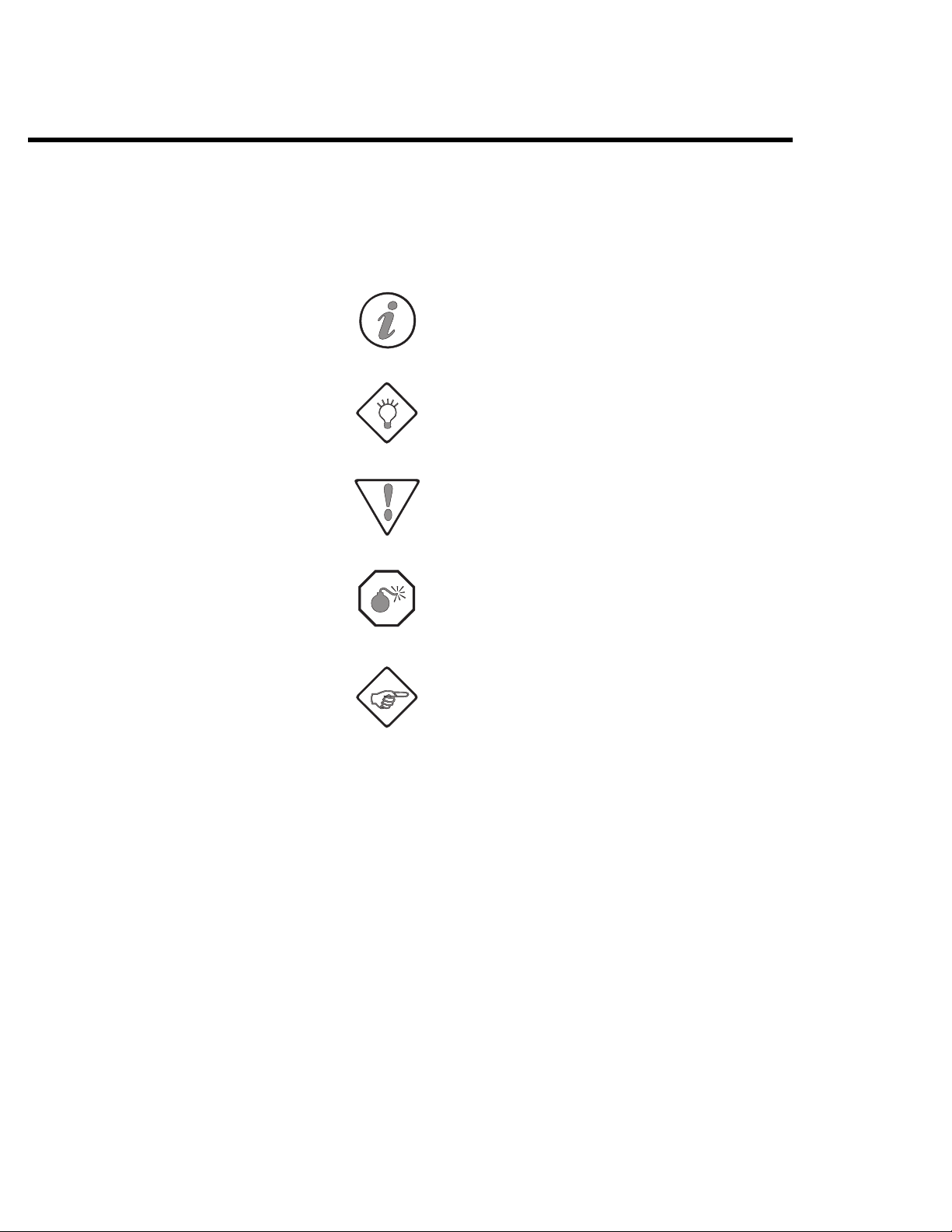
The following symbols will be used to highlight specific sections of text
throughout the manual.
3-1 would refer to Chapter 3,
xiii
Preface
Symbol Meaning
▲
Indicates an item in a list/grouping or a singlestep procedure
Note:
Indicates specific information that you should
read.
Hint:
Indicates a tip, new idea or helpful hint.
Caution:
Indicates a note of caution. You should pay
special attention to this section.
Warning:
Indicates a warning. You should read this section very carefully.
xiv
Important:
Please read this! Indicates a very important
message.

HELP-LINE
In order to provide a high-degree and quality of technical support, a
special HELP-Line is available for
help with the instrument, applying the instrument to a particular prob-
lem or help with the
port at the following numbers:
In Canada:
In the U.S.A.:
SMARTMAG users. If you need any
ENVIMAP software, please contact SCINTREX sup-
Telephone: (905) 669-2280
Fax: (905) 669-6403 (Sales Department)
(905) 669-9899 (Customer Service)
Telex: 06-964570
Telephone: (817) 591-7755
Fax: (817) 591-1968
HELP-Line
Preface
In Australia:
Telephone: (619) 321-6934
Fax: (619) 481-1201
xv

Preface
xvi

SMARTMAG
INTRODUCTION
This manual is divided into twelve chapters with the information flow
from chapter to chapter following a natural progression, as shown in
the following table:
Chapter Description
Introduction
Preparation
Guidelines
Chapter
Outlines what the instrument can do.
Describes the assembly of the system in
preparation for use.
Provides guidelines, hints and basic troubleshooting information that are common to all
SMARTMAG models.
1
Introduction
SM–4 Model
SM–4G Model
Console
Setting up
Provides step by step instructions on how to
use the SM–4
Provides step by step instructions on using the
SM–4G
Describes the physical parts of the
console, keypad and display menus. It also
describes the function of each key, as well as
the various modes and parameters shown on
the display panel.
Gives step-by-step instructions on how to set
up the instrument as either a total-field magnetometer, a gradiometer or a magnetic basestation.
SMARTMAG without the console.
SMARTMAG without the console.
SMARTMAG
1-1
Introduction
Chapter Description
COLD BOOT
Operations
Data Output
Maintenance
Reference
Appendix
Note: Please read the section “First time operation” on page 7–1 so
that you will know how to do a cold boot of the instrument.
This is needed the first time you use it, whenever you wish
to change operating configurations, or after the batteries
have been removed for more than 10 minutes.
Guides you through typical instrument operation, using basic and advanced configurations, in a
survey.
Shows examples of data output formats and
explains how to dump the acquired data to a
computer.
Describes basic maintenance, trouble-shooting and repair.
Contains the technical specifications, instrument parts list and warranty information.
Gives a detailed overview of issues relating to
optimum sensor orientation.
WALKMAG and a stop-and-go type of
1-2

INSTRUMENT OVERVIEW
Instrument overview
The SCINTREX SMARTMAG is an easy-to-use, light-weight, battery-powered,
portable magnetometer. It is a total-field instrument using the Larmor
frequency of precession of cesium atoms to measure the local magnet-
ic field. Optional upgrade kits allow the instrument to be used as a gra-
diometer or as a base-station.
Measured data is stored in memory along with the coordinates where
the measurement took place. In the advanced configuration modes,
you can also enter descriptive notes of up to 32 characters at any sta-
tion. The data can be displayed either numerically or graphically for
quick inspection of the data quality and spotting of anomalies. Data
can also be recalled from memory for visual inspection, dumped to the
serial port (RS-232) of a computer or directly to a printer. You can also
automatically correct your magnetic data for diurnal variations when
another
survey in the
To m a ke th e
site characterization, drum location, archaeology, general search,
ground water, mineral, oil and gas exploration. These configurations
fall into two categories: basic (where you only need to set a few param-
eters) and advanced (where you have complete control over all oper-
ating modes).
SMARTMAG is used as a base-station or when you conduct your
TIE mode.
SMARTMAG easy to use, there are preset configurations for
Introduction
The operating modes of the
or fully automatic. In the
data are acquired and recorded at rates of up to ten readings per sec-
ond, as you walk at a steady pace along the survey line. At desired in-
tervals, you trigger a station marker by pressing a single button and the
co-ordinates are automatically assigned to the recorded data.
Note that each model of the
quire additional software and/or hardware to be converted from one
model to another, if desired. Please consult your sales representative for
further information.
SMARTMAG can be manual, semi-automatic
WALKMAG (walking magnetometer) mode,
SMARTMAG (SM–1 through SM–4G) may re-
1-3

Introduction
1-4

SMARTMAG
Chapter
PREPARING THE SMARTMAG
This chapter describes:
▲ how the SMARTMAG is packaged,
▲ how to connect the components to get an operational unit,
▲ the various options you may have for powering the unit.
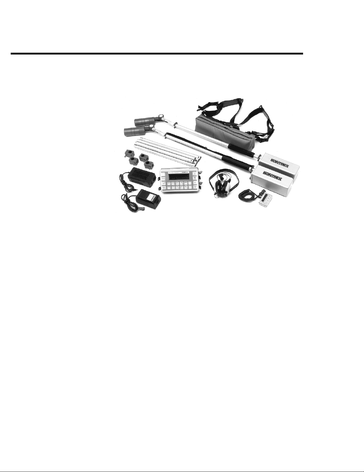
The following two photographs show all the components (less packing
materials) of the standard
SMARTMAG and the SMARTMAG Gradiometer.
2
Preparation
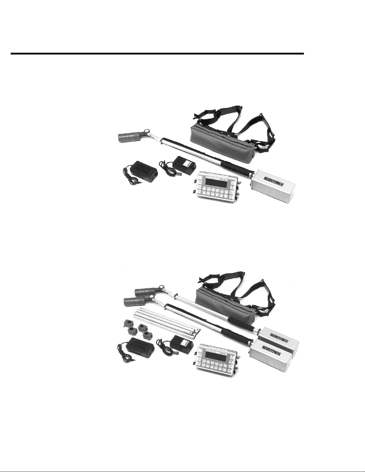
Figure 1 The complete SMARTMAG SM–4 kit
with optional accessories.
2-1
Preparing the SMARTMAG
Figure 2 The complete SMARTMAG gradiometer
kit with optional accessories.
UNPACKING
The standard SMARTMAG is shipped in a durable carrying/shipping case
that should be retained for storage and shipping. This provides a proper
place for every item when you repack your instrument for shipping or
storage. Please check the components delivered against the actual order, as systems may vary
REPACKING
Please make certain that the batteries are removed and stored in the ap-
propriate places. Failing to do so may result in damaged batteries and
possibly a damaged console.
2-2

Warning: The batteries must be removed from the unit prior to
shipping or storage.
FAILURE TO DO SO MAY RESULT IN DAMAGE.
ASSEMBLY
In order to make the system as compact as possible for shipment and
storage, and considering the various sensor configurations available,
the
SMARTMAG system requires you to connect up the external compo-
nents. This section will describe the steps required to completely as-
semble your instrument.
INSTALLING THE BATTERY BELT
The battery belt contains the batteries that power up the SMARTMAG sen-
sor assembly. The
stored within the console housing and is discussed in “SMARTMAG
console battery installation/exchange” on page 2–8.
SMARTMAG console is powered by batteries that are
Assembly
Preparation
2-3

Preparing the SMARTMAG
Figure 3 The Battery Belt
INSTALLING/EXCHANGING THE BATTERY IN THE BATTERY BELT
1. When installing replacement batteries, disconnect the existing
batteries and install the new ones.
2. Adjust the battery pouch velcro compartments to secure the
batteries in the pouch.
2-4
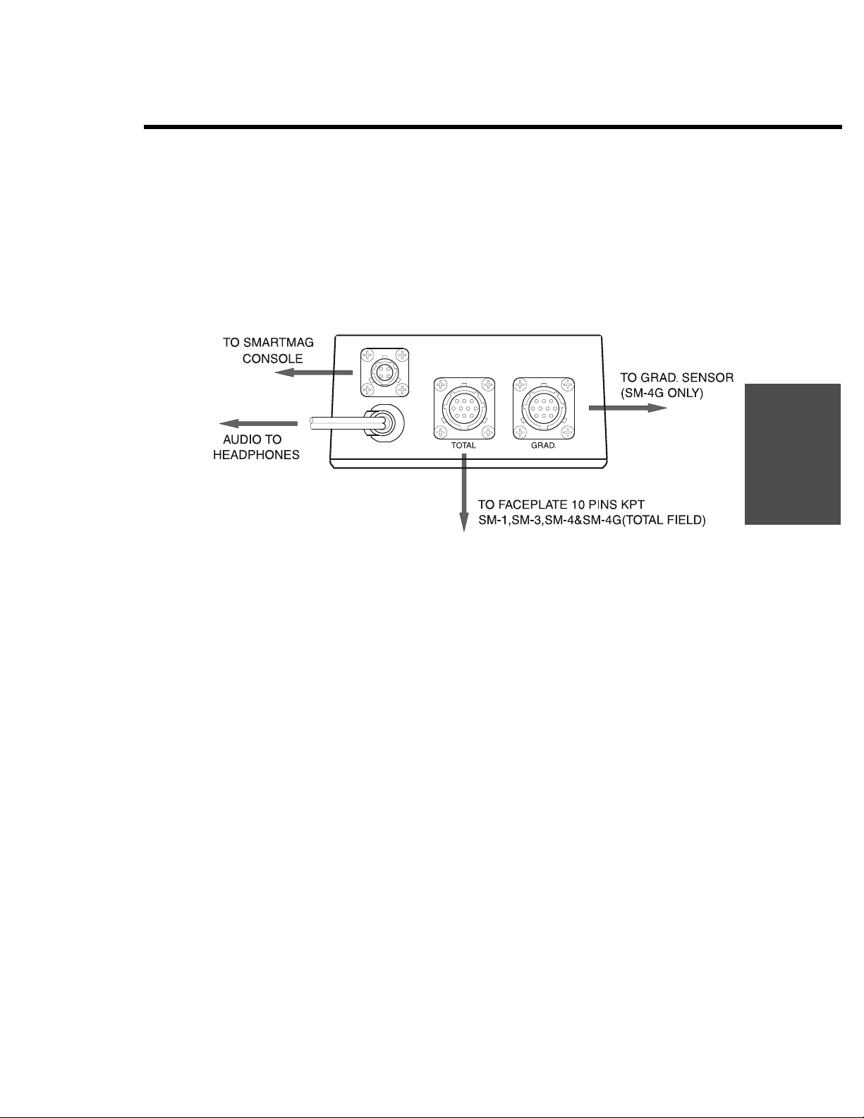
CONNECTING THE SENSOR(S) TO THE BATTERY BELT
1. Using the following diagram, connect the appropriate assemblies
to the connectors on the Battery Belt box which is located on the
underside of the Battery Belt.
Assembly
Preparation
Figure 4 Battery Belt Box Connectors
2-5

Preparing the SMARTMAG
INSTALLING THE LED DISPLAY AND KEYBOARD
1. Attach the mounting brackets to the sensor staff by using the four,
#4 Philips screws that are supplied with the mounting kit as shown
below. Ensure that the mounting bracket with the velcro is
mounted on the top of the staff.
2-6
Figure 5 LED and Keyboard Mounting Kit
2. Attach the display and keyboard to the top of the mounting
bracket with the velcro.
3. Connect the display and keypad connector to the rear of the
sensor compartment as shown in the diagram.
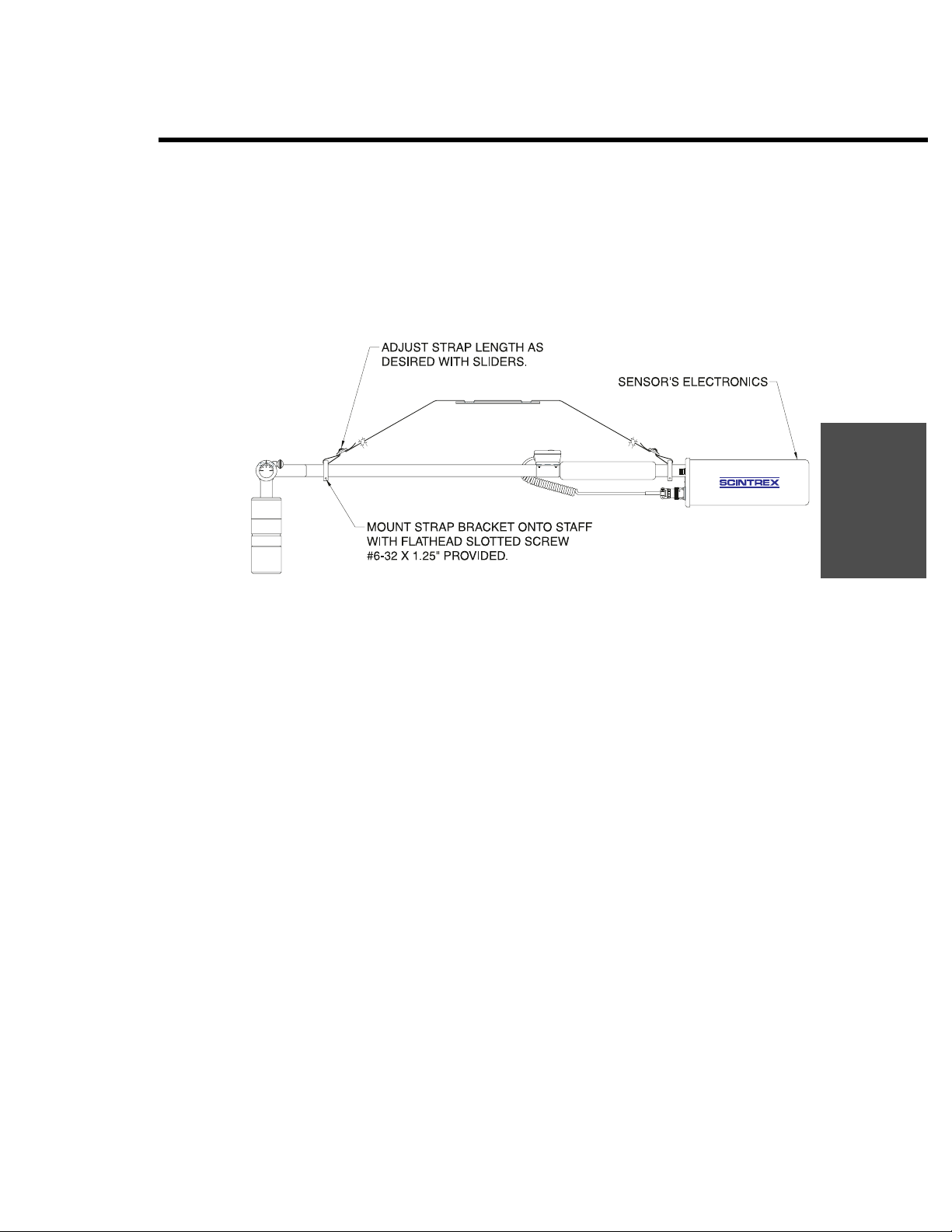
INSTALLING THE SHOULDER STRAP
1. Thread the shoulder strap through the plastic clips and attach the
strap to the sensor staff as shown in the diagram below:
Figure 6 Installing the shoulder strap
Assembly
Preparation
2. Adjust the straps in the plastic clips until the sensor staff is the
correct height and the strap comfortably fits your shoulder.
INSTALLING THE AUDIO OPTION KIT
The Audio option can be added to the SMARTMAG after you have taken
possession of the instrument by adding the audio option kit. To install
the audio option in your
SMARTMAG, please contact the factory.
2-7

Preparing the SMARTMAG
SMARTMAG CONSOLE BATTERY INSTALLATION/EXCHANGE
The SMARTMAG console is shipped without the battery installed. This is
the proper procedure, while shipping and storing the instrument, to
prevent deep discharge of the battery. Deep discharge can possibly
cause permanent damage to the battery and will always shorten the
battery life. This situation will occur because a small current is being
drawn even if the instrument is turned off.
The following steps outline the battery installation:
1. Turn the instrument face down on a clean and even surface.
2. Unscrew both knurled screws on either side of the battery cover
and lift the cover off.
3. Place the battery into the recess in the rear panel of the
instrument.
4. Connect it carefully to the MAIN BATTERY connector. It is not
important which side of the plug is up, as long as the connector
pins are properly aligned.
2-8
5. Replace the cover and tighten both knurled screws.
6. If this is the first time installation, proceed with battery charging.
The small size and low cost of the battery makes it convenient to carry
an additional battery along as a spare.
Warning: An internal battery keeps the memory and the internal
clock alive for about
the switching to the spare battery be done
TO PREVENT THE LOSS OF YOUR DATA!
10 minutes. It is strongly advised that
quickly,

Assembly
You need not worry about a low battery causing data loss, since the
memory power requirements are much less than those needed to make
a valid reading of the magnetic field.
Preparation
Battery cover
Figure 7 SMARTMAG battery pack
Battery pack
USING THE EXTERNAL BATTERY PACK
The standard battery should provide 24 hours operation at 20°C and 8
hours of operation at -40°C. Extended cold weather
may require more power than the standard battery together with a
spare can provide. To satisfy this additional requirement, the External
Heavy Duty Battery Pack (
provides about three times as much power as the standard battery. This
battery pack can be carried by the strap or attached to a belt.
To connect the external battery you must proceed as follows:
1. Turn the instrument face down on a clean and even surface.
2. Unscrew both knurled screws on either side of the battery cover.
3. Lift off the cover and store it somewhere convenient for future
use with the standard battery configuration.
4. Remove the standard battery.
SCINTREX part number 788 026) is available. It
WALKMAG surveys
5. Connect the connector in the dummy battery cover carefully to
the
MAIN BATTERY connector. It is not important which side of the
plug is up, as long as the connector pins are properly aligned.
2-9

Preparing the SMARTMAG
6. Place the new cover on to the console by gently pushing it into
7. Please check the battery voltage condition at this stage and
Dummy Battery Cover
SMARTMAG Console
(Face-down)
its place and tighten the knurled screws on both sides.
charge the battery, if it is required.
Battery Cable
External Heavy Duty
Battery Pack
Main Battery Connector
2-10
Figure 8 External heavy duty battery connection

USING AN EXTERNAL POWER SUPPLY
More demanding applications, such as an extended base-station oper-
ation, may require more power than can be provided with the either of
the
SCINTREX supplied battery packs. In this case you have two options:
a) AC-power
If a source of AC-power is available, the instrument can be run
while the charger is connected to it. You will also be charging the
standard internal battery, if it is installed, at the same time.
Note: Please be aware of possible magnetic noise from genera-
tors, and ensure that all cabling and sensors are as far away
as possible from the generator as possible.
b) 12-volt battery (car or marine)
A 12-volt car battery may be more appropriate for other
applications. The special External Power Cable (
788 029) should be used for this purpose.
Assembly
Preparation
SCINTREX P/N
1. The standard internal battery may be left in place.
2. Plug in the end of the cable with the single plug into the
Charger Connector at the right-rear side of the
console. (See item 6 in Figure 12 on page 6–2.)
3. Connect the end with the clips to the battery terminals.
The red cable-clip goes to the positive battery terminal. The
black cable-clip goes to the negative battery terminal.
Caution: The correct polarity must be used for the instrument to
operate properly.
SMARTMAG
2-11

Preparing the SMARTMAG
2-12

SMARTMAG
GUIDELINES
OPERATOR PREPARATION
Prior to conducting a search or survey with a cesium magnetometer,
the operator must remove all offending metallic items from his/her
body (some metals are non-magnetic or have low magnetic signature;
aluminum and brass for example). Commonly worn or carried magnet-
ic items include the following: belt buckles, watches, coins, steel toed
boots/shoes, metal buttons, pocket knives, compasses and magnets. It
may not always be obvious that an item contains metallic parts, for ex-
ample some shoes may have metallic eyelets. Of course, the
can be used to test suspect items.
Chapter
3
Guidelines
SMARTMAG
GEOMETRY OF DEAD ZONES
Cesium magnetometers will operate properly only if the angle that the
sensor head makes with the earth’s magnetic field vector is within the
ranges 10–85 degrees, 95–170 degrees, 190–265 degrees and 275–355
degrees. When the sensor head is parallel (more correctly in line,
which consists of parallel and antiparallel alignment) or at right angles
to the earth’s magnetic field vector, no usable signal is available. For a
small zone about parallel and right angle alignment there is still no us-
able signal. These zones are referred to as dead zones and are illustrated
in Figure 9 on page 3–2.
3-1

Guidelines
For parallel alignment we have two dead zones, the first about 0 degrees with range –10 to +10 degrees and the second about 180 degrees
with range 170–190 degrees. These two zones are referred to as the po-
lar dead zones and form two conical solid angles in three-dimensional
space.
For right angle alignment, we have a dead zone whenever the sensor
head is in the plane perpendicular to the earth’s magnetic field vector.
This zone is encountered whenever the angle that the sensor head
makes with the earth’s magnetic field vector is in the range of 85–95 (or
265–275) degrees. This zone may be considered as a disk in threedimensional space, and is referred to as the equatorial dead zone.
3-2
Figure 9 Cesium sensor dead zones in the
northern hemisphere.

Determining operating zones
DETERMINING OPERATING ZONES
1. To determine the operating zones of the SMARTMAG, face north
and swing the sensor head to the ground and then upwards. This
will enable you to determine the angular range of operation by
either the audio or display reading. When the sensor head is out
of the operating range, the audio will vary wildy and the display
reading will go out of range (range 20,000 to 99,999 nT). Preferably, the staff should be oriented so that it lies in the center of the
angular range as just described.
2. While facing magnetic north, the range of sweep operation may
be determined by swinging the
then to the right. The usable sweep angle will depend on your
geographical position. If sweep operations are then conducted
while walking in a northerly direction, the allowable sweep
motion will be known by the previous test.
SMARTMAG staff to the left and
3. To determine the proper staff position and sweep angle for
walking south, perform the previous tests while facing south.
Guidelines
3-3

Guidelines
ADJUSTING THE SENSOR HEAD ANGLE
1. Adjust the angle of the sensor head relative to the staff by loosen-
ing the brass wing nut and then swiveling the head. The head
should be positioned so that it is in the centre of the operating
zone and that it does not enter a dead zone during a survey operation.
2. When the sensor head is in the appropriate position, tighten the
brass wing nut.
3-4

SMARTMAG
Chapter
THE SMARTMAG MODEL
SM–4
This chapter is about the SMARTMAG model SM–4 which contains a full
featured
numerical and graphical data. The SM–4 features:
▲ adjustable cesium sensor with rigid staff,
▲ SMARTMAG Console featuring:
LCD console. The SM– 4 console has full storage for recording
▲ graphics display
▲ full keyboard
▲ 310,000 Readings —Total Field
4
▲ 750,000 Reading —Base Station
▲ Non-magnetic waterproof construction
RECEIVING YOUR INSTRUMENT
On receipt of your instrument, carefully inspect the shipping or carry-
ing case for damage. Also ensure that you have received all required as-
semblies by checking against your order, as systems may vary.
SM–4
4-1

The SMARTMAG Model SM–4
THE COMPONENTS
The basic SM– 4 (part no. 759 003) consists of the following assemblies
(see “Instrument parts list” on page 11–4 for more details):
▲ SMARTMAG main assembly (759 009)
▲ Rechargeable battery belt (759 043)
▲ 110/220 VAC battery charger (400 151)
▲ Shoulder strap (759 504)
▲ SMARTMAG minor spare parts kit (759 039)
▲ SMARTMAG console (759 012)
▲ Rechargeable battery (400 078)
▲ 110/220 VAC battery charger (400 139)
▲ Console minor spare parts kit (788 030)
▲ RS-232 Cable (745 081)
▲ SMARTMAG SM–4/4G Information kit (759 534)
▲ Transit case (759 505)
ASSEMBLING THE INSTRUMENT
The shoulder strap assembly are not attached to the instrument when
shipped. The shoulder strap is attached to the staff by way of clips that
are snapped on and then screw tightened. The clamps are to be positioned on either side of the black foam handle on the staff. This will require some experimentation to find the most comfortable position for
the individual user.
CONNECTING THE CABLES
In order to operate the SMARTMAG you must provide power to the staff
assembly by connecting the cable (with 10 pin KPT connector) from
the battery belt (this connector is labeled ‘
nector on the face plate. This connector is locked by rotating the
mounting ring on the connector in a clockwise direction. (See “Connecting the sensor(s) to the Battery Belt” on page 2–5.) (Cable P/N 759
513)
4-2
TOTAL’) to the mating con-

Setting up the instrument
The optional LED display and keypad is similarly connected to the other
connector (10 pin KPT) on the face plate.
The headphones are connected to its signal cable coming from the cen-
ter of the battery belt box.
The
SMARTMAG console is connected via RS-232 cable (with dual 4-pin
KPT cable P/N 759 514) to the battery belt box. Connect the ‘Data Out-
put’ connector on the
tor on the battery belt box. This 4 pin RS-232 connector is on the bottom
of the battery belt box, and is adjacent to the 10 pin ‘
SMARTMAG console to the 4-pin RS-232 connec-
SETTING UP THE INSTRUMENT
TURNING ON THE INSTRUMENT
TOTAL’ connector.
1. Set the 3-position switch in the battery belt to the ON position. The
amber coloured
2. Press and release the RESET push-button switch on the face plate
of the
SMARTMAG.
If the 3-position switch in the battery belt is put in the center or
STBY (standby) position, the sensor head power is removed but
digital electronics remains powered. This mode may be used
when learning the display functions if you want to conserve
battery power.
Note: The instrument operates from battery power only — the
charger will not power the instrument and the charger will
not charge the batteries in any position other than the
position of the 3-position switch.
LED will then light.
OFF
4-3
SM–4

The SMARTMAG Model SM–4
USING THE HEADPHONES
The headphones are connected to the black plastic connector at the
end of the cable coming from the bottom of the battery belt. The headphones are monaural and have a single volume control on the right
hand cup.
The sensitivity of the headphone is set by the PITCH parameter on the
SMARTMAG console. Alternatively, the sensitivity of the headphones can
be set with the Audio function accessed by the
LED display and key-
board described below.
SETTING THE PARAMETERS WITH THE
CONSOLE
4-4
Prior to operating a survey, it is necessary to enter certain parameters
into the
▲ hemisphere of operation
▲ local field value
▲ audio sensitivity
▲ sample rate
▲ filter bandwidth
SMARTMAG console. These include:
These parameters are downloaded into the sensor wand from the
SMARTMAG console when the START key is first pressed on the console.
The message initializing will be displayed on the
console
the
LCD display. If a communication error results, press and release
RESE T button on the SMARTMAG faceplate.
Note: SM–4 users (and particularly SM– 4G users) will find the
SMARTMAG
LED
display and keypad useful for verifying that the sensor
wands have reset and are fully functioning. Please refer to
Chapter 6 for a full description of the
SMARTMAG console.

Using the LED display and keypad
USING THE LED DISPLAY AND KEYPAD
Note: The SM– 4 may be used as a search magnetometer using the
optional
LED display and keyboard in place of the console.
The parameters may be set from the
bly which consists of an 8 digit, sunlight readable display and a four key
keyboard. The keys are labeled with both arrows and numbers
(1,2,3,4). The functions are as follows:
KEYPAD
Function key—(1 key, right arrow) This key is used to enter and exit
!
@#
$
functions. The available functions may be viewed by using the scroll
keys.
Scroll keys—(2 key, up arrow; 3 key, down arrow) These keys are used
to scroll or scan through functions. Once a function has been selected
or entered (by pressing Key 1), the scroll keys are then used to scroll or
scan through the options provided by that function.
Auxiliary Key—(4 key, left arrow) The auxiliary key is currently re-
served for future use.
DISPLAYS AND FUNCTIONS
LED display and keyboard assem-
SM–4
Function ‘ ’
(blank display)
This display shows the total field value in nT.
1. Press the
displayed.
2. Press the
3. Press the
or # scroll key until the ‘ ’ (blank display) is
@
function key to display the total field value in nT.
!
function key to exit this parameter.
!
4-5

The SMARTMAG Model SM–4
Function
north
south
Function
Audio
Select this function to enter in the North or South hemisphere. In order
to operate properly, the hemisphere setting must be set according to the
hemisphere that the instrument is being operated in. If you are operating in the northern hemisphere, (Canada, USA, Japan etc.) select
north, Otherwise, select south. The default power up setting of
the
SMARTMAG is for northern hemisphere operation.
1. Press the
is displayed.
2. Press the
3. Press the
4. When you have selected the appropriate hemisphere, press the
function key to exit this parameter,
!
Select this function to set the sensitivity of the audio headphones. The
sensitivity can be set from 0 to 990 in increments of 10.
1. Press the
2. Press the
3. Press the
selected. The sensitivity can be set from 0 through 990 in
increments of 10. The default is 100. Use a smaller value for less
sensitivity and a larger value for greater sensitivity.
or # scroll key until the either north or south
@
function key to access the setting.
!
or # scroll key to select either north or south.
@
or # scroll key until Audio is displayed.
@
function key to access the setting.
!
or # scroll key until the appropriate sensitivity is
@
Function
LoPAS
4-6
Select this function to set the low-pass filter bandwidth in Hz of the displayed data. This function does not affect audio information. The visual
display of the total magnetic field may b e u se d to sup pl eme nt the aud io
information. The bandwidth settings are 0.5, 1.0, 2.0, 4.0 and 8.0 Hz (optionally higher bandwidths are available).
1. Press the
2. Press the
3. Press the
selected. The bandwidth can be set to 0.5, 1.0, 2.0, 4.0 or 8 Hz (or
optionally higher).
or # scroll key until the LoPAS is displayed.
@
function key to access the setting.
!
or # scroll key until the appropriate bandwidth is
@

Using the LED display and keypad
Note: Bandwidths and sample rates are independent — data may
be obtained at the highest sample rate regardless of the
bandwidth setting.
Function
fLASH
Function
rAtE
Function
FIELd
Select this function to program the FLASH memory
1. Press the
2. Press the
3. Press the
10 in increments of 1 (0, 1, 2, …10). When 10 is reached, the
SMARTMAG will be ready to receive its new operating program
from a
1. The PC program FASTCOM
2. A downloadable sys file *.SYS
3. RS-232 cable to connect the battery belt’s 4 pin KPT
connector to PC
Access this function to select the LED display update rate of 1, 2, 5 or 10
readings per second.
Access this function to set the local field strength in 1,000’s of nT to the
nearest 5,000 nT. This parameter does not have to be correctly set for the
SMARTMAG to function, so you can determine the correct value of the
field by measuring the field with the
field settings are:
or # scroll key until FLASH is displayed.
@
function key to access the setting.
!
key to increment the displayed number from 0 to
@
PC via RS-232 at 19,200 baud. This requires:
SMARTMAG. Some examples of
SM–4
Local Field: Set FIELd to:
23,000 nT 25 (for 25,000 nT)
57,000 nT 55 (for 55,000 nT)
90,000 nT 90 (for 90,000 nT)
The field parameter may be set ±10 without effect. If the field is grossly
out of setting, bandwidth settings will not be correct. To set the field:
4-7

The SMARTMAG Model SM–4
1. Press the
2. Press the
3. Use the
strength by 5 (5,000 nT).
Warning: Users who operate with both the
and
the operating parameters in the
Changes made to the operation parameters such as
bandwidth via the
process of data collection will be recognized by the sensor
wand processor but will not be recorded in the
console header information.
or # scroll key until FIELd is displayed.
@
function key to access the setting.
!
or # scroll key to increment or decrement the field
@
SMARTMAG console simultaneously should configure
PERFORMING A SURVEY
LED display and keypad
SMARTMAG console only.
LED display and keypad while in the
SMARTMAG
4-8
See the SMARTMAG Applications booklet for details on how to perform
a survey.

SMARTMAG
HE SMARTMAG MODEL
T
SM–4G
This chapter is about the SMARTMAG model SM–4G which contains a
full featured
sole has full storage for recording numerical and graphical data. The
SM–4G features:
▲ gradiometer interconnect poles.
▲ two cesium sensors with adjustable sensor orientation,
▲ SMARTMAG Console featuring:
LCD console and the gradiometer option. The SM– 4G con-
▲ graphics display
▲ non-magnetic water proof construction
Chapter
5
▲ storage for 190,000 gradiometer readings
▲ full keyboard
RECEIVING YOUR INSTRUMENT
On receipt of your instrument, carefully inspect the shipping or carry-
ing case for any damage. Also, please ensure that you have received all
required assemblies by checking against your order, as systems may
vary.
SM–4G
5-1

The SMARTMAG Model SM–4G
THE COMPONENTS
The basic SM– 4G SMARTMAG (part no. 759 004) consists of the following assemblies (see also “Instrument parts list” on page 11–4):
▲ SMARTMAG main assembly (759 009)
▲ Rechargeable battery belt (759 043)
▲ 110/220 VAC battery charger (400 151)
▲ Shoulder harness (759 504)
▲ SMARTMAG minor spare parts kit (759 039)
▲ SMARTMAG console (759 012)
▲ Rechargeable battery (400 078)
▲ 110/220 VAC battery charger (400 139)
▲ Console minor spare parts kit (788 030)
▲ RS-232 Cable (745 081)
▲ Gradiometer mounting kit (759 082)
▲ SMARTMAG SM–4/4G Information kit (759 534)
▲ Transit case (759 505)
ASSEMBLING THE INSTRUMENT
The shoulder strap assembly is not attached to the instrument when
shipped. The shoulder strap is attached to the staff by means of clips
that are snapped on and then screw tightened. The clamps are to be positioned on either side of the black foam handle on the staff. This will
require some experimentation to find the most comfortable position for
the individual user.
MASTER PROCESSOR
When operating in the Gradiometer configuration with two sensor
wands, the wand connected to the battery belt
pin
KPT) will process both the Total and Gradiometer signals. The
5-2
TOTAL connector (10

Assembling the instrument
TOTAL sensor wand transmits both total and gradiometer data to the
SMARTMAG console via the 4 pin KPT connector on the bottom of the
battery box (this connector is adjacent to the
TOTAL connector).
Note: The
erate as a master processor. The
internally jumpered to operate as a slave processor.
When receiving a SM–4G system, the
slave) sensor wands will be labelled.
Warning: Please consult the
changing these configurations. Note that both master and
slave processor wands may be used as is for performing
total field surveys.
CONNECTING THE CABLES
In order to operate the SMARTMAG you must provide power to the staff
assembly by connecting the cable (with 10 pin
the battery belt (this connector is labeled
nector on the face plate. This connector is locked by rotating the
mounting ring on the connector in a clockwise direction. (See “Con-
necting the sensor(s) to the Battery Belt” on page 2–5.). (Cable P/N 759
513)
TOTAL sensor wand must be internally jumpered to op-
GRAD sensor must be also
TOTAL (or master) and GRAD (or
SCINTREX factory for information on
KPT connector) from
TOTAL) to the mating con-
Similarly, the gradiometer sensor is connected to the battery belt con-
nector labelled
The optional
connector (10 pin
GRAD.
LED display and keypad is similarly connected to the other
KPT) on the face plate.
The headphones are connected to its signal cable coming from the cen-
ter of the battery belt box.
The
SMARTMAG console is connected via RS-232 cable (with dual 4-pin
KPT cable P/N 759 514) to the battery belt box. Connect the ‘Data Out-
put’ connector on the
SMARTMAG console to the 4 pin RS-232 connector
on the battery belt box. This 4 pin RS-232 connector is on the bottom
of the battery belt box and is adjacent to the 10 pin
TOTAL connector.
5-3
SM–4G

The SMARTMAG Model SM–4G
SETTING UP THE INSTRUMENT
TURNING ON THE INSTRUMENT
1. Set the 3-position switch in the battery belt to the ON position. The
amber coloured
2. Press and release the RESET push-button switch on the face plate
of the
SMARTMAG. (Gradiometer: press both buttons on each of
the face plates.)
If the 3-position switch in the battery belt is put in the center or
STBY (standby) position, the sensor head power is removed but
digital electronics remains powered. This mode may be used
when learning the display functions if you want to conserve
battery power.
Note: The instrument operates from battery power only — the
charger will not charge the batteries in any position other
than the
LED will then light.
OFF position of the 3-position switch.
USING THE HEADPHONES
The headphones are connected to the black plastic connector at the
end of the cable coming from the center of the battery belt. The headphones are monaural and have one volume control on the right hand
cup.
The sensitivity of the headphones is set by the PITCH parameter in the
SMARTMAG console. Alternatively, the sensitivity of the headphones can
be set in the Audio function accessed by the
board described in the following sections.
5-4
LED display and key-

Setting the parameters with the SMARTMAG console
SETTING THE PARAMETERS WITH THE
SMARTMAG CONSOLE
Prior to operating a survey, it is necessary to enter certain parameters
into the
▲ sample rate
▲ local field value
▲ hemisphere of operation
▲ filter bandwidth
▲ audio sensitivity
These parameters are downloaded into the sensor wand from the
SMARTMAG console when the START key is first pressed on the console.
The message initializing will be displayed on the
console LCD display. If a communication error results, press and release
the
the SM–4G.
SMARTMAG console. These include:
SMARTMAG
RESET button on the SMARTMAG faceplate (or both RESET buttons for
Note: SM–4 users (and particularly SM– 4G users) will find the
display and keypad useful for verifying that the sensor
wands have reset and are fully functioning. Refer to Chapter
6 for a full description of the
SMARTMAG console.
USING THE LED DISPLAY AND KEYPAD
The SM – 4G may be used as search magnetometer/gradiometer using
the optional
The parameters may be set from the
bly which consists of an eight digit, sunlight readable display and a four
key keyboard. The keys are labeled with both arrows and numbers
(1,2,3,4). The functions are as follows:
LED display and keyboard in place of the LCD console.
LED display and keyboard assem-
LED
SM–4G
5-5

The SMARTMAG Model SM–4G
KEYPAD
Function key—(1 key, right arrow) This key is used to enter and exit
!
@#
$
functions. The available functions may be viewed by using the scroll
keys
Scroll keys—(2 key, up arrow; 3 key, down arrow) These keys are used
to scroll or scan through functions. Once a function has been selected
or entered (by pressing Key 1), the scroll keys are then used to scroll or
scan through the options provided by that function.
Auxiliary Key—(4 key, left arrow) The auxiliary key is currently reserved for future use.
DISPLAYS AND FUNCTIONS
Function ‘ ’
(blank display)
Function
north
south
This display shows the total field value in nT.
1. Press the
displayed.
2. Press the
3. Press the
Select this function to enter in the North or South hemisphere. In order
to operate properly, the hemisphere setting must be set according to the
hemisphere that the instrument is being operated in. If you are operating in the northern hemisphere, (Canada, USA, Japan etc.) select
north, Otherwise, select south. The default power up setting of
the
SMARTMAG is for northern hemisphere operation.
1. Press the
is displayed.
2. Press the
3. Press the
4. When you have selected the appropriate hemisphere, press the
function key to exit this parameter,
!
or # scroll key until the ‘ ’ (blank display) is
@
function key to display the total field value in nT.
!
function key to exit this parameter.
!
or # scroll key until the either north or south
@
function key to access the setting.
!
or # scroll key to select either north or south.
@
5-6

Using the LED display and keypad
Function
Audio
Function
LoPAS
Select this function to set the sensitivity of the audio headphones. The
sensitivity can be set from 0 to 990 in increments of 10.
1. Press the
2. Press the
3. Press the
selected. The sensitivity can be set from 0 through 990 in
increments of 10. The default is 100. Use a smaller value for less
sensitivity and a larger value for greater sensitivity.
Select this function to set the low-pass filter bandwidth in Hz of the dis-
played data. This function does not affect audio information. The visual
display of the total magnetic field may b e u se d to sup pl eme nt the aud io
information. The bandwidth settings are 0.5, 1.0, 2.0, 4.0 and 8.0 Hz (op-
tionally higher bandwidths are available).
1. Press the
2. Press the
3. Press the
selected. The bandwidth can be set to 0.5, 1.0, 2.0, 4.0 or 8 Hz (or
optionally higher).
or # scroll key until Audio is displayed.
@
function key to access the setting.
!
or # scroll key until the appropriate sensitivity is
@
or # scroll key until the LoPAS is displayed.
@
function key to access the setting.
!
or # scroll key until the appropriate bandwidth is
@
Function
fLASH
Note: Bandwidths and sample rates are independent — data may
be obtained at the highest sample rate regardless of the
bandwidth setting.
Select this function to program the FLASH memory
1. Press the
2. Press the
3. Press the
10 in increments of 1 (0, 1, 2, …10). When 10 is reached, the
SMARTMAG will be ready to receive its new operating program
from a
or # scroll key until FLASH is displayed.
@
function key to access the setting.
!
key to increment the displayed number from 0 to
@
PC via RS-232 at 19,200 baud. This requires:
SM–4G
5-7

The SMARTMAG Model SM–4G
1. The PC program FASTCOM
2. A downloadable sys file *.SYS
3. RS-232 cable to connect the battery belt’s 4 pin KPT
connector to
PC
Function
rAtE
Function
FIELd
Access this function to select the LED display update rate of 1, 2, 5 or 10
readings per second.
Access this function to set the local field strength in 1,000’s of nT to the
nearest 5,000 nT. This parameter does not have to be correctly set for the
SMARTMAG to function, so you can determine the correct value of the
field by measuring the field with the
SMARTMAG. Some examples of
field settings are:
Local Field: Set FIELd to:
23,000 nT 25 (for 25,000 nT)
57,000 nT 55 (for 55,000 nT)
90,000 nT 90 (for 90,000 nT)
The field parameter may be set ±10 without effect. If the field is grossly
out of setting, bandwidth settings will not be correct. To set the field:
1. Press the
2. Press the
3. Use the
strength by
or # scroll key until FIELd is displayed.
@
function key to access the setting.
!
or # scroll keys to increment or decrement the field
@
5 (5,000 nT).
5-8
Warning: Users who operate with both the
and
SMARTMAG console simultaneously should configure
the operating parameters in the
Changes made to the operation parameters such as
bandwidth via the
LED display and keypad while in the
process of data collection will be recognized by the sensor
wand processor but will not be recorded in the
console header information.
LED display and keypad
SMARTMAG console only.
SMARTMAG

ASSEMBLING THE GRADIOMETER
The gradiometer option can be assembled either horizontally or verti-
cally. The gradiometer kit has six 0.5 metre inter-connecting poles.
Vertical Gradiometer
The vertical gradiometer is configured by using two 0.5 metre inter-
connecting poles to attain a vertical separation between the two sensor
staff assemblies, as shown in the diagram below:
Using the LED display and keypad
Figure 10 Assembling the Vertical Gradiometer
SM–4G
5-9

The SMARTMAG Model SM–4G
Horizontal Gradiometer
In the horizontal gradiometer assembly, there are two options. The gradiometer separation in the horizontal position can be 0.5, 1.0 or 1.5
metres. The separation is achieved by the number of inter-connecting
polesused in the configuration. For example, if you require a 1.5 metre
separation, all of the poles would be used. See the diagram below for
a typical horizontal configuration.
5-10
Figure 11 Assembling the Horizontal
Gradiometer

PERFORMING A SURVEY
See the SMARTMAG Applications booklet for details on how to perform
a survey.
Performing a Survey
5-11
SM–4G

The SMARTMAG Model SM–4G
5-12

SMARTMAG
Chapter
6
THE SMARTMAG CONSOLE
This chapter is about the the SMARTMAG console and fully describes:
▲ the keypad functions,
▲ the various display menus,
▲ the display formats that you will encounter.
PRE-DEFINED OPERATING MODES
To ma ke the SMARTMAG easier to use, it has a menu of seven predefined
configurations, in three modes, to choose from. The menu is obtained
by pressing the “SETUP + ON” keys simultaneously.
BASIC ▲ used for site characterization, buried ordnance detection, drum
location and archaeology
▲ operates in the WALKMAG mode (continuous reading)
▲ does not have on-line data recall features; you have to dump the
data to a computer to inspect it—you can still see a graphical
display of the data
▲ data correction is from a base-station or the TIE-PT Loop mode
▲ real-time graphic display of the data
Console
SEARCH ▲ operates in a continuous reading mode, but the data is not
stored in memory
▲ you can see a graphical display of the data as it is collected
▲ real-time graphic display of the data
ADVANCED ▲ used for ground water, mineral, oil and gas exploration or
detailed site characterization, drum location, archaeology, etc.
▲ allows you to adjust all possible parameters of the SMARTMAG
▲ real-time graphic display of the data
6-1

The SMARTMAG Console
1
2
3
3
4
5
6
7 8 9 10
6-2
Figure 12 The SMARTMAG console.
11

Console description
*
CONSOLE DESCRIPTION
# Item Description
1 Keypad The fully sealed Keypad has 19 keys and a sound port.
Console
2 Liquid Crystal
Display (LCD)
3 Carrying Strap
Attachment
*Sensor
4
Connectors
5 Data Output
Connector
6 Charger/
External Power
Connector
7 Charging Light The charging light is visible through a window at the left side of
The large 8 line by 40 character (64 x 240 dots) Supertwist
LCD (with a wide temperature range) presents status and data
in numeric or graphic format.
Four rings at the side of the console allow attachment of the
carrying harness.
Up to two sensor connectors may be present at the left hand
side of the console. The nearer one (J102) is reserved for the
magnetometer.
The data output connector carries RS-232 data dump signals,
as well as the analog signal for a strip chart recorder and is located at the right hand side of the console.
It has the following pin assignments:
A - common (ground), C - RS-232 transmit data,
B - RS-232 receive data. D - analog out O - 1 Volt,
This connector accepts the charger to recharge either the
standard battery or the external heavy-duty battery pack. It
also accepts external, well filtered, 11 to 16 Volt DC input.
The center pin is negative (–).
The shell is positive (+).
the console. It is lit while the battery is charging at a high rate.
8 Battery
Compartment
9 Desiccant
Cartridge
10 Battery A rechargeable lead-acid battery in the standard
11 Fuse The standard 1.5A fuse to use with the standard battery.
*
The number of sensor connectors may vary depending upon configuration
The battery compartment is located at the back of the console
and contains one rechargeable lead-acid battery, the desiccant
cartridge and the fuse. The battery cover is replaced with another cover with a cable attached when the external battery is
used.
The desiccant cartridge is a cylindrical re-usable capsule filled
with a drying agent. It absorbs any moisture that may get inside the instrument.
SMARTMAG configuration.
6-3

The SMARTMAG Console
KEYPAD DESCRIPTION
The keypad has 19 keys. Two of the most used keys are duplicated on
the right and left sides of the console for easy access. Some keys have
up to three separate functions assigned to them. The response of these
multi-function keys depends upon the operation in progress.
Note: The function mode of the keys has precedence over the
alphanumeric mode of the keys
.
6-4
Figure 13 The SMARTMAG console keypad.

KEY FUNCTIONS
Key Description
q
Keypad description
Console
Turns the instrument on and off. Turning the instrument off during a reading abruptly terminates a reading with the loss of the
current data.
Starts or stops an operation, such as data acquisition, data
dumping, data recall, etc.
w
5
1
23
e
*When the instrument is in the Notes operation, this button
acts as a “backspace” key to delete entries.
*Accesses the various setup displays. The actual setup menu
that will be displayed depends upon the display screen in which
this key is pressed.
*Accesses the Auxiliary Functions display allowing:
▲ setting of the LCD intensity,
▲ data output,
▲ locking of the setup parameters,
▲ reprogramming of the main system software (EEPROM).
Moves the cursor to the left or up; to the right or down,
▲ scrolls sequentially through graphic display pages (online),
▲ scrolls sequentially through graphic display pages (recall).
Two identical keys:
▲ opens and closes the parameter fields during setups,
▲ opens and closes the scaling option field for the graphics display,
▲ toggles the sample rate in the walking type survey.
0
Allows escape from a deeper level in a program to a higher level,
ultimately to the top level, which is signified by the
Main operating display.
Aborts a data dump.
6-5

The SMARTMAG Console
Key Description
*Accesses the Info. Display, which allows:
7
t
6
4
9
▲ setting of date and time,
▲ entering of serial and job numbers and operator identification,
▲ observation of memory availability.
Two identical keys:
▲ moves the cursor from one sub-page to the next sub-page,
▲ moves the cursor to the next character location during note entry,
▲ advances the station number by station separation in the
walking mode.
*Accesses the Note Entry display, which allows:
▲ the entry of five common notes (macros) to be recorded
repeatedly with selected readings,
▲ the entry of unique notes to be recorded with a particular
reading.
Toggles the data display between numerical and graphic data
presentation during data acquisition only.
*Presents the Recall display for selection of:
▲ data item to be recalled,
▲ setting of the starting location or time of the recall.
6-6
r
8
*Manually records measured data and notes in internal
memory.
Acts as the START key at a Tie-point. This is used for the
Tie-point line and loop mode corrections.

Keypad description
Key Description
Facilitates the scrolling forward or backward through a list of
items:
=-
1-9, ., A-Z *Allows alpha-numeric entry for setups and notes.
BEEPER PORT
+
q
1
▲ allows sign entry to numbers,
▲ allows panning along a line of data during recall,
▲ increments or decrements the line and station number in the
Stop-and-Go mode.
This blank “key” in the upper left corner of the console is not actually a key, but a flexible membrane to enhance the loudness of
the beeper.
Pressing the “ON” and “AUX/LCD” keys simultaneously performs the COLD BOOT operation, resetting the instrument to
factory defaults.
Console
q
+
5
Pressing the “ON” and “SETUP” keys simultaneously allows you
to select between Basic, Search or Advanced modes.
*These items/key functions are only operational when you
select the advanced operating modes (options 5 to 7) from the
initial configuration menu.
6-7

The SMARTMAG Console
DISPLAY SCREENS
The SMARTMAG currently has seven preset configurations. Depending
upon which of the configurations you choose to survey with, you may
not see all of the various types of displays:
▲ configuration selection menus
▲ help screens
▲ confirmation screens
▲ parameter selection screens
▲ note entry screens
▲ numeric data displays
▲ graphical data displays
▲ pop-up options and confirmations
GENERAL INFORMATION
Most of the screens contain three bands of information as shown below:
Title Line
Specific
Display
Info.
Prompts
6-8
WELCOME TO SMARTMAG APPLICATIONS
MENU
1-Buried Ordnance Det.
2-Drum Location
3-Archaeology
4-Search Magnetometer
more +-
Please Select Your Application #:
Figure 14 General display information bands
1. The Title Line at the top indicates the current operating func-
tions.
2. The middle six lines contain specific display information
consisting of either instrument and survey parameters or data.
3. The bottom line usually contains prompts for actions, such as
pressing the key required to start an operation. Miscellaneous

23
Display screens
messages may also appear here. The battery voltage (a value
between 100 and 140) is also shown on the right-side of this line.
Note: The instrument automatically turns off (blank display) to
conserve battery power, if there is no reading or key stroke
detected for one minute.
Cursor
A large, blinking cursor (❚) indicates the specific parameter that can
be altered to change setups, starting station value, station or line spac-
ing, and so on. The cursor is moved from parameter to parameter or
line to line by pressing the arrow (← →) keys to move in the desired di-
rection. The prompt on the bottom line will let you know which key to
press to make any changes.
Display blocks
Some displays are divided into two or more blocks or sub-panels. The
blocks are separated by solid partition lines as shown in the following
figure.
Console
Cursor
Prompt
t
Separator
BlockBlock
START
locationsmeasurement
of:
MAG: mmmm ST: sss.s d
SEP: ppp.p
DIVBY: 0.
LN:llll.l d
SEP: pppp.p
Figure 15 Instrument display showing information
blocks (sub-panels)
To move the cursor from one block to another, press the “NEXT” key.
6-9

The SMARTMAG Console
Some measured data is displayed on more than one page (display
screen). Switching between pages is also done by pressing the “NEXT”
key. The display screens are designed so that these multi-page displays
do not have separate sub-blocks. All of this is discussed in detail under
“Advanced mode data displays” on page A6–27.
Pop-up windows
Some displays will have pop-up windows (either on the right or left side
of the main display) that will contain:
▲ prompts for selecting or changing parameters
▲ confirmations and warnings of impending operations requiring
▲ status indication of an operation under way, such as data output
a Y (yes) or N (no) entry from the keypad
MODE: t-fld
locations
BW: 8Hz
PITCH: 100 ST: 10. E
LOCAL FLD. 50000 SEP: 25.
TM/DT: OUTPUT: DIVBY: 0.
BASE: TIE: LN: 1. N
HEM:N ERASE MEM.: SEP: 10.
Chg?:ENT. 000 help:INFO BATT:134
locations
TIME: 13:40:35
DATE: 94/10/02 ST: 0. +
SEP: 0.
DIVBY: 0.
Main Menu: ESC LN: 0. +
SEP: 0.
Chg?:ENT. 000 help:INFO BATT:134
Figure 16 Sample pop-up windows
6-10

=
-
-
Display screens
Help screens
On-line help is also available. There are three screens of information
providing a quick reference on how to do most operations and which
buttons to push. The screens are as follows:
Cold Boot:AUX-ON simult.
Follow setup inst. bottom left line
To change application:SETUP-ON simult.
Switch Window:NEXT
Read:START/STOP..Tie point read:TIE
On-line, NEXT to tag station
Main Menu: ESC 1.0 more +-
On-line, rate than 1,2,5,0=10 read/sec
Read end:GRAPH/NUM, NEXT to view data
On graph:ENTER recall,+-Scale, 0 center
On num, beep on=+, off=Appl. 1-3 Base Fld. default to 50000
To reprogram system:Appl.#5,6,7 AUX/LCD
Console
=
=
-
7
Main Menu: ESC 1.0 more +-
HOT/MENU KEYS: (appl. 5,6,7)
SETUP: Main instrument, method setup
NOTE: Define notes,macros
RECALL: Off-line data recall
INFO: tm/dt,oper,job#,ser#,batt,mem
AUX: LCD intens.,output,look, Rep,OS
Main Menu: ESC 1.0 more +-
Figure 17 Help screens available
The help screens are displayed when you press the “INFO” button.
Whenever you see the text help:INFO in the bottom prompt line of
a display, you can activate the help screens.
6-11

The SMARTMAG Console
To toggle to the another help screen, press the “+” or “–” key. The
=-
screens change in a cyclical manner as shown in the above
figure.
To return to the main operating menu, press the “ESC” key.
0
OPERATING DISPLAYS
The various display screens will be discussed in groups according to
the configuration modes—basic, search or advanced.
BASIC MODE CONFIGURATION DISPLAYS
The basic mode of operation is in effect when you select either of these
5q
configuration options after pressing the “SETUP+ON” keys simultaneously:
Title Line
Display
Specific
Info.
Prompts
6-12
1. Buried Ordnance Det.
2. Drum Location
3. Archaeology
The following is the general layout of the Main operating display in the
basic mode:
MODE: t-fld
locations
BW: 8 Hz
PITCH: 100 ST: 0. +
LOCAL FLD.: 50000 SEP: 0.
TM/DT: OUTPUT: DIVBY: 0.
BASE: TIE: LN: 0. +
HEM:N ERASE MEM.: SEP: 0.
Chg?:ENT. help:INFO BATT:119
Battery strength
Figure 18 General display layout

The following table describes all the parameters in the two blocks of the
main menu:
Parameter Description
MODE
Allows you to select the SMARTMAG operating mode:
▲ total-field magnetometer
▲ gradiometer
▲ base
You must press the “+” or “–” keys to toggle between the
modes.
Operating displays
Console
BW
PITCH
LOCAL FLD.
TM/DT
Bandwidth.
You have a choice of 0.5, 1, 2, 4 or 8 Hz (or optionally higher
bandwidths).
This is the audio headphone sensitivity. You can select in increments of 10 from 0 to 990. The default is set to 100.
The value of the Earth's ambient magnetic field in the survey
area.
For best performance the local field should match the ambient
field as closely as possible, at least to within ±10,000 nT.
This option allows you to set the time and date of your
SMARTMAG.
You must press the “ENTER” key.
A pop-up window will be displayed showing the current values of
TIME and DATE in your instrument. Use the arrow keys to move
the blinking cursor to the field you wish to change. Press
“ENTER” again and enter the value from the keypad. Finish the
entry by pressing “ENTER” one more time.
To get back to the main menu, press the “ESC” key.
NOTE: If you will be using a base-station to correct the data,
you must ensure that the date and time of both units are the
same BEFORE you start collecting data.
6-13

The SMARTMAG Console
Parameter Description
OUTPUT
BASE
TIE
This option dumps your data to a computer via the serial port.
The communications mode is fixed to 9600 baud, 8 bits, 1 stop
bit and no parity. The format will be XYZ+.
You must press the “ENTER” key.
An information pop-up will be displayed telling you to press the
“START” key when you are ready. You must have a computer
connected using the supplied RS-232 cable (SCINTREX part no.
745 081) and you should be running the ENVIMAP software
(
Prepare the Data:Dump instrument data
This option applies a BASE-STATION correction using data supplied from a base-station SMARTMAG.
You must press the “ENTER” key.
You need to have the base-station connected as described in
“Base-station operation” on page A8–11.
A request for confirmation will be displayed in a pop-up window
before your data is corrected. You must press the “9/YZ” (Yes)
key to begin or the “5/MNO” (No) key to abort.
NOTE: The original raw data is changed.
This applies the LOOP mode correction to collected data.
menu option)
HEM
ERASE
MEMORY
6-14
You must press the “ENTER” key.
A request for confirmation will be displayed in a pop-up window
before your data is corrected. You must press the “9/YZ” key
to begin or the “5/MNO” key to abort.
NOTE: The original raw data is changed.
This function sets the hemisphere function of either north or
south. N=north, S=south
Allows clearing of the data memory.
You must press the “ENTER” key.
A request for confirmation will be displayed in a pop-up window
before the actual erasure takes place. You must press the
“9/YZ” (Yes) key to begin or the “5/MNO” (No) key to abort.
NOTE: The rest of the setup parameters remain intact.

Parameter Description
Operating displays
ST
SEP
DIVBY
The station number for this measurement.
It consists of the numeric part (
part (
d).
The range is from 0 to 99999 with a decimal point as required.
The direction allows the entry of the geographical direction or
the Cartesian co-ordinates. The allowed entries are: N,E,S,W,
+ or –.
The line or station separation.
The range is from 0 to 99999 with a decimal point, as required,
and can either be positive (+) or negative (–). It may not necessarily represent the reading separation.
When the separation is positive, the station number gets
incremented by the separation.
When the separation is negative, the station number gets
decremented by the separation.
NOTE: a negative (W,S,–) station, when incremented, becomes
less negative, and vice versa.
Trigger switch closure counter. See “SMARTMAG Distance
Trigger” on page A6–42.
sss.s) and the directional
Console
LN
Chg?:+_
ENTER
The line number, along which the measurements take place.
It consists of the numeric part (
part [
d].
The range is from 0 to 99999 with a decimal point as required.
The direction allows the entry of the geographical direction or
the Cartesian co-ordinates and is one of: N,E,S,W, + or –.
Depending upon which field the cursor is located in, you will see
one of these prompts.
Chg?:+- allows you to toggle a selection from an internal list
by pressing either the “+” or “–” keys.
ENTER: Pressing “ENTER” will either pop-up a window for fur-
ther operation or let you enter a numeric value (terminated by
another press of the “ENTER” key)
llll.l) and the directional
6-15

The SMARTMAG Console
Parameter Description
help:INFO
BATT
Reading
Previous
readings
Magnetic
value
This prompt indicates that the help screens are available when
you press the “INFO” key.
The voltage of the main battery. The normal range is between
100 and approximately 140 when the charger is connected.
The instrument may turn off without warning when the value
drops below 100 and will not allow more measurements.
The data however still remains intact in memory, as long as the
main battery remains connected.
Basic mode data collection displays
The numeric display screen during data collection is as follows:
00 -* MAG *- 12:20:25
TOTAL NOISE LN: 0 E
57800.71 0.05 ST: 100 N
57800.70 0.05 RATE: 5 101 N
57800.72 0.05 102 N
57800.71 0.05 103 N
MEMF: 95%
Reading.. BATT: 119
Noise
Survey parameters
Free memory Battery strength
6-16
Figure 19 Data collection displays
Note: The sample rate can be set to 1, 2, 5 or 10 samples per sec-
ond. The default setting is 5 samples per second.
Alternately, during data collection, the data may be displayed graphically.

4
23
4
Operating displays
1. Press the “NUM/GRA” key to display a profile of the data points as
they are collected along the line (LN). Up to 178 readings can be
displayed. The display appears as follows:
-*MAG*TOTAL
57800.71
LN:
100S
ST:
50E
Reading..
Figure 20 Graphical display of a survey line.
2. While in the graphics mode, you can press the cursor keys to
display the alternate graphical displays (gradiometer only).
3. Press the “NUM/GRA” key to return to the numerical diplsay
mode from the graphic display mode.
Console
SEARCH MODE CONFIGURATION DISPLAY
This mode is selected when you choose the following option from the
configuration menu (available after pressing the “SETUP+ON” keys
simultaneously):
4. Search Magnetometer
The Main operating display in the Search mode is as follows:
MODE: srch.
BW: 8 Hz
PITCH: 100
LOCAL FLD.: 50000
HEM:N
Chg?:ENT. help:INFO BATT:119
Figure 21 Search mode main display screen
6-17

The SMARTMAG Console
Parameter Description
MODE The mode is fixed to “search.” The text srch. is displayed as
a reminder only.
BW
PITCH
LOCAL FLD.
HEM
Chg?+_
ENTER
Bandwidth. Bandwidth and sample rates are independent —
data may be obtained at the highest sample rate regardless of
the bandwidth setting.
You have a choice of 0.5, 1, 2, 4 or 8 Hz (or optionally higher
frequencies).
This is the audio headphone sensitivity. You can select in increments of 10 from 0 to 990. The default is set to 100.
The value of the Earth's ambient magnetic field in the survey
area.
For best performance the local field should match the ambient
field as closely as possible, at least to within ±10,000 nT.
This function sets the hemisphere function of either north or
south. N=north, S=south
Depending upon which field the cursor is located in, you will see
one of these prompts.
Chg?:+- allows you to toggle a selection from an internal list
by pressing either the “+” or “–” keys.
ENTER: Pressing “ENTER” will either pop-up a window for fur-
ther operation or let you enter a numeric value (terminated by
another press of the “ENTER” key)
help:INFO
BATT:
6-18
This prompt indicates that the help screens are available when
you press the “INFO” key.
The voltage of the main battery. The normal range is between
100 and approximately 140 when the charger is connected.
The instrument may turn off without warning when the value
drops below 100 and will not allow more measurements.
The data however still remains intact in memory, as long as the
main battery remains connected.

Reading
Previous
readings
Operating displays
Search mode data collection displays
The numeric display screen during data collection is as follows:
Console
00 -* MAG *- 12:20:25
TOTAL NOISE LN: 0 E
57800.71 0.05 ST: 100 N
57800.70 0.05 RATE: 5 101 N
57800.72 0.05 102 N
57800.71 0.05 103 N
MEMF: 95%
Reading.. BATT: 119
Magnetic value
4
Noise
Figure 22 Numeric data collection display during
Alternately, you can push the “NUM/GRA” key to display a profile
(of up to 178 data points) of data as it is collected in the Search
mode. The display appears as follows:
*MAG*TOTAL
57800.71
LN:
100S
ST: 50E
Reading..
Figure 23 Graphical display during Search mode.
Free memory
Battery strength
Search mode
Note: The values that you see for the line and station in the numer-
ic display are the last ones entered in a previous mode. The
search mode does not use these for any purpose, so please
ignore them.
6-19

The SMARTMAG Console
ADVANCED MODE CONFIGURATION DISPLAYS
The advanced mode of operation is in effect when you select either of
5q
these configuration options after pressing the “SETUP+ON” keys simultaneously:
5. Ground Water Exploration
6. Mineral Exploration
7. Oil and Gas Exploration
Main operating display
The advanced mode Main operating display appears as follows:
00000 START 00000 of:
measurement
locations
MAG: mmmm ST: sss.s d
SEP: pppp.p
DIVBY: 0.
LN: llll.l d
SEP: pppp.p
Measure:START 00000 ALL keys BATT:bbb
Figure 24 Main operating display in advanced
mode
The configurable parameters of the Main operating display are:
Parameter Description
MAG mmm shows which type of magnetometer measurement is cur-
rently enabled, and therefore ready to be started.
ST
The station number for this measurement.
It consists of the numeric part (
part [
d].
The range is from 0 to 99999 with a decimal point as required.
ssss.s) and the directional
6-20
The direction allows you to enter the geographical direction or
the Cartesian co-ordinates as one of: N,E,S,W, + or –.

Parameter Description
Operating displays
SEP
DIVBY
LN
The line or station separation.
The range is from 0 to 99999 with a decimal point, as required,
and can either be positive (+) or negative (–). It may not necessarily represent the reading separation.
See the “NEXT” key and AUTO. St. INC. for more information.
When the separation is positive, the station number gets incremented by the separation.
When the separation is negative, the station number gets decremented by the separation.
Note: a
less
Trigger switch closure counter. See “SMARTMAG Distance
Trigger” on page A6–42.
The line number, along which the measurements take place.
It consists of the numeric part (
part [
The range is from 0 to 99999 with a decimal point as required.
The direction allows you to enter the geographical direction or
the Cartesian co-ordinates as one of: N,E,S,W, + or –.
negative
negative, and vice versa.
d].
(W,S,–) station, when incremented, becomes
llll.l) and the directional
Console
6-21

The SMARTMAG Console
Instrument setup display
This display enables you to configure the basic data acquisition portion
5
of the
SMARTMAG. This display is accessible with the “SETUP” key.
instrument setup
instrument setup
MAG SETUP: ->menu AUTO ST.INC.: no
CYCLE REPEAT: no
ERASE MEMORY: no
HEATER: no
Chg?: ENT. BATT:119
Figure 25 SMARTMAG instrument setup display
Parameter Description Default
MAG SETUP
AUTO ST.INC.
CYCLE REPEAT
Displays the magnetometer specific setup menu.
Pressing the “ENTER” key gets the next menu.
A “yes/no” toggle that controls the automatic
station increment (decrement).
no for the base station, walking or manual type of
operation.
yes for semi-automatic operation.
Determines whether the magnetometer will take one
reading only, or will continuously take readings at the
time interval specified by the DURATION parameter in
the Mag. Setup.
no
no
ERASE MEMORY
HEATER
6-22
This is
which is set in the Mag Setup.
Allows clearing of the data memory. A request for
confirmation will be displayed before the actual erasure takes place.
NOTE: The setup parameters remain intact.
Enables or disables the LCD display heater. If the
temperature is above -15 degree C, enabling this parameter has no effect.
not applicable for Base Station operation,
no
no

5
Operating displays
Magnetometer setup display
This display provides access to the parameters affecting the operation
of the magnetometer portion of the
ble from either the Instrument setup display, or from the Main operating
display (by using the short-cut, i.e. pressing the “ENTER” key).
mag setup
MODE: t-fld CYCLE TIME: 0
RATE: 5 CHART SCALE:100
BW: 8 Hz BASE FIELD:50000
LOCAL FLD.: 50000 TIE-MODE: line
BASE CORRECT: no AUTO RECORD:yes
TIE CORRECT: no HEM:N PITCH:100
Chg?:ENT. help: INFO BATT:b119
Figure 26 Magnetometer setup display.
SMARTMAG. This display is accessi-
Console
Parameter Description Default
MODE:
RATE:
BW:
LOCAL FLD.:
Allows the selection of:
▲ Total Field Magnetometer (
▲ Gradiometer
▲ Base Station
▲ Off (will disable the SMARTMAG).
This is the sample rate (per second) of the audio
output:
Bandwidth. Bandwidth and sample rates are independent — data may be obtained at the highest sample
rate regardless of the bandwidth setting.
You have a choice of 0.5, 1, 2, 4 or 8 Hz (or optionally
higher frequencies).
The value of the Earth's ambient magnetic field in the
survey area.
For best performance, the local field should match
the ambient field as closely as possible, at least to
within ±10,000 nT.
default
)
t-fld
5
8 Hz
0
6-23

The SMARTMAG Console
Parameter Description Default
BASE CORRECT:
TIE CORRECT:
CYCLE TIME: The reading interval of the base station.
A “yes/no” toggle that applies a BASE-STATION
correction using data supplied from a base-station
SMARTMAG.
You must press the “+” key to toggle the
You need to have the base-station connected as described in “Base-station operation” on page A8–11.
A request for confirmation will be displayed in a popup window before your data is corrected. You must
press the “9/YZ” (Yes) key to begin or the “5/MNO”
(No) key to abort.
NOTE: The original raw data is changed.
A “yes/no” toggle that applies a tie-point correction
using data collected in the TIE mode.
Selecting this opens a window indicating which tiepoint (loop or line) correction mode is in effect. You
must enter “Y” to start the correction.
NOTE: The original raw data is changed.
The allowable range is 0 to 9999 seconds.
no
yes on.
no
0
CHART SCALE:
6-24
Entering 0 (zero) results in a reading interval equal to
the reading time.
The instrument goes to "sleep" between readings, for
4 seconds and up.
This function enables you to set the scale of the
graphical diaplay chart
100

Operating displays
Parameter Description Default
BASE FIELD:
TIE MODE:
AUTO RECORD:
The base field is used in conjunction with the
station correction
The base-station correction technique removes variation in the ambient field during the time that the
base station is running. However, variations taking
place from day to day are not corrected. The base
field value is used for this purpose.
The actual value is not critical, as long as it is the
same for all instruments in the survey. It is important
that this value not be changed during the entire survey. A logical value is the first reading of the basestation on the first survey day.
Allows to select either the Line or Loop type of tieline correction.
Note: The Tie-line correction method is substantially
less precise
od.
A “yes/no” toggle.
This function is used in the semi-automatic mode to
save you from having to press another key.
procedure.
than the base-station correction meth-
base-
0
Console
line
no
HHEM:
PITCH:
Auto Record is always in effect in the base-station
operation
in the SMARTMAG Instrument Setup.
This sets the hemisphere function to either north or
south:
or
if the Cycle Repeat function is selected
N=north,
S=south
This is the audio headphone sensitivity. You can select
in increments of 10 from 0 to 990.
The default is set to 100.
N
100
6-25

The SMARTMAG Console
ADVANCED MODE DATA DISPLAYS
Data is displayed on a page by page basis in either numeric or graphic
4
Last
reading
Previous
readings
form. There are up to three pages each. The “NUM/GRA” key toggles between the two display forms.
Numeric data display
Numeric displays are only available when the instrument is recording
data, i.e. you cannot “recall” the data in a tabular format as shown below.
The displays shown in the examples below are the numeric data displays for the total field, base station and gradiometer. Note that the
noise is not available in the gradiometer display.
The total-field and the base-station displays do not differ.
-*MAG*- 12:20:25
TOTAL1 NOISE LN: 0E
57800.71 0.05 ST: 100N
57800.70 0.05 101N
57800.72 0.05 102N
Reading.. BATT: 119
RATE: 5 103N
MEMF: 95%
6-26
Sample rate
Figure 27 The numeric data display for total field
and base station.
Free memory
Battery strength
-*MAG*- hh:mm:ss
TOTAL1 TOTAL2 GRADIENT LN:llllld
mmmmm.m mmmmm.m ggggg.g ST:sssssd
mmmmm.m mmmmm.m ggggg.g sssssd
mmmmm.m mmmmm.m ggggg.g sssssd
mmmmm.m mmmmm.m ggggg.g sssssd
MEMF: nn%
BATT: bbb

Operating displays
Display Item Description
.
TOTAL1 The magnitude measured by the first total-field sensor in
nanoTeslas (nT).
The most current reading is the
readings.
TOTAL2 The magnitude measured by the second total-field sensor in
nanoTeslas (nT).
The most current reading is the
readings.
NOISE
GRADIENT
TIME The current time in hours:minutes:seconds.It is used to time
A number indicating the quality of the survey and individual
readings.
It is the fourth digital difference calculation done on consecutive readings. It is useful for determining overall noise and noise
spikes.
The magnetic gradient between the two sensors.
Expressed in nT/m = (TOTAL 1 - TOTAL 2)/SEP, where SEP is the
sensor separation in metres.
stamp each reading.
top
most followed by preceding
top
most followed by preceding
Console
LN
ST
MEMF
BATT
The line number on which this measurement took place.The value consists of the numeric and directional parts.
The station number to which the respective magnetic data applies.The value consists of the numeric and directional parts.
The percentage of free memory.
Measurements can be made when the memory is full, however
the data is no longer recorded.
The voltage of the main battery. The normal range is between
100 and approximately 140 when the charger is connected.
The instrument may turn off without warning when the value
drops below 100 and will not allow more measurements.The
data however still remains intact in memory as long as the main
battery remains connected.
6-27

The SMARTMAG Console
Graphic data display
If you are in the numeric data display, press 4 to access the graphic data
display. Then press either 2 or 3 to access different pages.
The display shown below is page three of the graphic data for the gradiometer. Page one and two appears identical, except that the word
“GRADIENT” is changed to either “TOTAL 1” or “TOTAL 2” and a
plot of the respective total field is shown.
The graphic displays are available while reading. Use the scroll keys to
select different graphic pages.
-*MAG*GRADIENT
LN:
ST:
ggg.g
llll.ld
ssss.sd
Figure 28 Graphic data display of page 3.
Display Item Description
GRADIENT
LN
ST The station number, at the cursor position, to which the re-
6-28
The display title indicating the data shown by the graph.
The numeric value indicated by
dient, at the indicated Line and Station number.
The line number along which this measurement took place (consisting of the numeric and directional parts).
spective magnetic data applies (consisting of the numeric and
directional parts).
ggg.gg is the respective gra-

RECALL DISPLAYS
The “RECALL” function is useful to view the collected and stored data.
Recall setup display
This display allows you to select the type, location or time and date of
9
the data. This display is accessed by pressing the “RECALL” key.
MAG: t-fld grad. base LN: llll.l d
Recall: START BATT: bbb
Operating displays
Console
recall locations
START of:
ST: ssss.s d
TM: hh:mm:ss
DT: yy:mm:dd
Figure 29 The recall setup display.
Display Item Description
MAG
LN
ST
TM
DT
The mode of the data collected.
Either one of Total Field, Gradient or Base Station.
The line number whose data is to be recalled, consisting of the
numeric and directional parts.
The station number is the starting location for the recall, consisting of the numeric and directional parts.
The starting time of the recall.
This parameter is only present when the Base Station
is selected.
The date of the data to be recalled.
This parameter is only present when the Base Station is selected.
6-29

The SMARTMAG Console
Display Item Description
BATT
The voltage of the main battery. The normal range is between
100 and approximately 140 when the charger is connected.
The instrument may turn off without warning when the value
drops below 100 and will not allow more measurements.
The data however still remains intact in memory as long as the
main battery remains connected.
Note: Not only the Time and Date, but the Line and Station num-
bers must also be correct to successfully recall Base Station
data.
Recall data display
Data can be recalled only in graphic form. Up to 178 readings can be
shown at one time. The display window can be moved sideways (called
panning) in steps of one half of its width (i.e. up to 89 readings) to view
adjacent data with the aid of the “+” or “–” keys. It is also possible to adjust the vertical scale and bring any point to the vertical center of the
window.
6-30
w
Exact values can be read off the numerical section at the left hand side
of the display.
The Total Field display is shown and explained. The Gradient display
differs in title only. The Base Station display shows Time and Date instead of Line and Station. Note that there are two pages of data for the
gradiometer.
These displays are accessible with the “START” key when in the Recall
Setup display.

-*MAG*TOTAL1
57800.71
LN:
100S
ST:
50E
Reading.
Figure 30 The recall data display.
Display Item Description
Operating displays
Console
TOTAL
LN
ST
The title of the display indicating the data shown by the graph.
The numeric value indicated by
total-field value, at the indicated line and station number. The
scroll keys may be used to view alternate pages.
The line number along which this measurement took place, consisting of the numeric and directional parts.
The station number to which the respective magnetic data applies, consisting of the numeric and directional parts, at the
cursor position
. See the next page for more on cursor position.
mmmmm.mm is the respective
6-31

The SMARTMAG Console
Modifying the display window
The graph can be altered by changing the vertical scale or by centering
any point vertically in the window. A smaller window can be opened
up using the “ENTER” key to allow changes. The changes take effect after you next press “ENTER.”
-*MAG*TOTAL1
57800.71
LN:
ST:
SCL: 00
100S
50E
Figure 31 The Recall display ready for customizing
Display Item Description
.
SCL Shown after the "ENTER" key is pressed.
It indicates the vertical full scale.
Scrolling using the +/– keys allows the full scale values of 1, 10,
100, 1000, or 10,000 nT.
This is the cursor, which is normally at the left edge
0
of the window.
It can be moved with the aid of the ←, → cursor keys.
Numerical data at the left hand side of the display represents
the data at the cursor position.
Pressing the “0” key adjusts the display such that the point at the cursor
position becomes the center value of the graph.
6-32

AUXILIARY DISPLAY
The Auxiliary display is accessible by pressing the “AUX/LCD” key. It
3
provides additional functions which are not directly accessible from
the keyboard. You will need to press the appropriate key to get to the
function.
Select function
Operating displays
Console
auxiliary functions
(+- ESC) LCD Intensity
(1) Data Output
(2) Factory Test # 0
(3) Lock OFF
(4) Reprogram System
Figure 32 The auxiliary functions display.
Key pressed Action under: auxiliary functions
=-0
1
2
3
4
These keys allow you to adjust the intensity of the LCD screen
for better viewing under a variety of lighting conditions.
This option allows you to access the Data Output menu to
transfer information to your computer or printer.
This function is reserved for production and service tests. It
has no functions for you to use.
The lock option allows you to lock the SMARTMAG setup parameters so that they are not accidentally changed. To make any
changes, you will have to toggle this option first.
This option allows you to update your SMARTMAG’s EPROM
with more functionality. The software is supplied by SCINTREX.
6-33

The SMARTMAG Console
DATA OUTPUT DISPLAY
This display allows the selection of:
▲ communication parameters between the SMARTMAG and the
output device such as a computer or printer,
▲ the data format of the output,
▲ and possibly the Line number, if a line by line data dump is
desired.
The data can be dumped in its entirety at once, or selectively on a mode
basis.
This display is accessible from the Auxiliary display.
START of:
locationsoutput
BY LN: yn
:all data recorded LN: l lll.l d
MAG: t-fld grad. base
BAUD: bbbbb
DL: ttt
BIT:b
FMT: xxxxx
Output: START BATT: bbb
Figure 33 The data output display.
Parameter Description Default
: all data
recorded
MAG
With the cursor placed after the colon, all the data
in the instrument would be dumped sequentially into
one, possibly very large file.
Lists the modes available for the SMARTMAG. As
shown, only the gradiometer data would be dumped
as indicated by the cursor position
6-34

Operating displays
Parameter Description Default
BY LN
LN The line number whose data has to be dumped, con-
BAUD
DL
yes/no
Directs the instrument to dump the data on a line by
line basis, in addition to a method by method basis.
This is usually left at no.
sisting of the numeric and directional parts.
The baud rate of communication with the
output device.
The following choices are available by scrolling:
600, 1200, 2400, 4800, 9600, 19200, 38400,
57600 baud.
A delay which may be added after each carriage
return/linefeed (CR/LF) to accommodate slow
peripherals such as some printers.
The range is 0 to 999 ms.
This value is normally left at 0 for dumping to
computers.
The proper setting has to be established experimentally for other equipment. Problems usually are
indicated by the loss of a few characters.
no
Console
9600
0
BIT
FMT The output data format.
The number of data bits.
The default value is 8 bits, which usually works properly.
The proper setting has to be established experimentally. For example, on some EPSON printers, 7 or 8
bits results in either normal or italic print.
The formats are described briefly in the following
table on page A6–38.
8
6-35

The SMARTMAG Console
Parameter Description Default
BY LN
LN The line number whose data has to be dumped, con-
BAUD
DL
yes/no
Directs the instrument to dump the data on a line by
line basis, in addition to a method by method basis.
This is usually left at no.
sisting of the numeric and directional parts.
The baud rate of communication with the
output device.
The following choices are available by scrolling:
600, 1200, 2400, 4800, 9600, 19200, 38400,
57600 baud.
A delay which may be added after each carriage
return/linefeed (CR/LF) to accommodate slow
peripherals such as some printers.
The range is 0 to 999 ms.
This value is normally left at 0 for dumping to
computers.
The proper setting has to be established experimentally for other equipment. Problems usually are
indicated by the loss of a few characters.
no
9600
0
BIT
FMT The output data format.
6-36
The number of data bits.
The default value is 8 bits, which usually works properly.
The proper setting has to be established experimentally. For example, on some EPSON printers, 7 or 8
bits results in either normal or italic print.
The formats are described briefly in the following
table on page A6–38.
8

Operating displays
Parameter Description Default
BY LN
LN The line number whose data has to be dumped, con-
BAUD
DL
yes/no
Directs the instrument to dump the data on a line by
line basis, in addition to a method by method basis.
This is usually left at no.
sisting of the numeric and directional parts.
The baud rate of communication with the
output device.
The following choices are available by scrolling:
600, 1200, 2400, 4800, 9600, 19200, 38400,
57600 baud.
A delay which may be added after each carriage
return/linefeed (CR/LF) to accommodate slow
peripherals such as some printers.
The range is 0 to 999 ms.
This value is normally left at 0 for dumping to
computers.
The proper setting has to be established experimentally for other equipment. Problems usually are
indicated by the loss of a few characters.
no
Console
9600
0
BIT
FMT The output data format.
The number of data bits.
The default value is 8 bits, which usually works properly.
The proper setting has to be established experimentally. For example, on some EPSON printers, 7 or 8
bits results in either normal or italic print.
The formats are described briefly in the following
table on page A6–38.
8
6-37

The SMARTMAG Console
Parameter Description Default
BATT The voltage of the main battery.
The normal range is between 100 and approximately
140 when the charger is connected. The instrument
may turn off without warning when the value drops
below 100 and will not allow more measurements.
The data however still remains intact in memory as
long as the main battery remains connected.
6-38

Operating displays
Data output formats
The following table shows the available output formats for dumping the
data to a computer or printer:
Data output
format
XYZ XYZ is the simplest format, suitable for software packages
Description
such as ENVIMAP.
It contains no heading or comments.
The individual data items are separated by a single space
character.
X and Y represent the cartesian coordinates
(N and E are positive, while S and W are negative).
Z is one or more items of magnetic data.
There is one set of data per printed line, including the time of
the measurement.
Console
CAUTION: Due to the lack of header information, you should
label the files clearly.
XYZ+ XYZ+ is identical to XYZ, but a header and user entered NOTES
are added.
XYZ++ XYZ++ is identical to XYZ+, but the data is now placed into
columns.
PRN PRN is a format used with software for the SCINTREX MP-3/4
Magnetometer.
NOTES NOTES outputs a report of all user entered NOTES, cross-
referenced with the Line and Station number.
BINARY Outputs all data in compact binary format (non-ascii). Requires
the DOS program BINDUMP to receive the binary data. The binary file created by BINDUMP may then be converted into any
of the above formats by the DOS program XFSMART*
*BINDUMP and XFSMART are supplied with the SMARTMAG
6-39

The SMARTMAG Console
NOTES DISPLAY
The notes display is useful for the entry of comments, which are stored
with the data at the particular Line and Station number.
Macros (pre-recorded messages) provide a quick entry for repetitive
notes which can be entered while measuring. This display is accessible
with the “NOTE” key.
NOTES:
#nnnnnnnnnnnnnnnnnnnnnnnnnnnnnnnn
MACROS:
1: ccccccccccccccc 2: ccccccccccccccc
3: ccccccccccccccc 4: ccccccccccccccc
5: ccccccccccccccc
Chg?:ENT. BATT:bbb
Figure 34 The NOTES display.
Parameter Description
NOTES
MACROS
1:
...
5:
6-40
Alpha-numeric characters, including "+", "." and " –",
up to 32 characters
A note can be saved as one of five macros in a separate memory
for re-use.
MACROS are pre-recorded messages of up to 15 characters.
These are used to speed up note entry.
It is most advantageous to enter frequently encountered
items, such as
road, fence
, and so on.

Parameter Description
Operating displays
BATT
The voltage of the main battery. The normal range is between
100 and approximately 140 when the charger is connected.
The instrument may turn off without warning when the value
drops below 100 and will not allow more measurements.
The data however still remains intact in memory as long as the
main battery remains connected.
Console
6-41

The SMARTMAG Console
INFORMATION DISPLAY
This display screen is used for the entry of ancillary information. You
7
Parameter Description
can also see how much free memory is available. This screen is accessed from the main display by pressing the “INFO” key.
scintrex data acquisition system v1.0
TIME: hh:mm:ss SER.#: sssssssss
DATE: yy:mm:dd JOB #: jjjjjjj
Chg?:ENT. help:INFO BATT: bbb
Figure 35 The INFO display.
OPERATOR: oooooooooo
MEMF: ppp%
Vx.x
TIME The current time of day.
DATE The present date.
SER.#
JOB #
OPERATOR
MEMF
BATT
The version number of the SMARTMAG internal software.
This is usually the serial number of the instrument. No use is
made of this number by the instrument, therefore it also could
represent the users inventory number. Up to 8 digits are accepted.
This may be the survey project number. Up to 6 digits are accepted.
This is the operator's name or number. It can contain up to 10
characters.
The percentage of free memory available for further use.
The voltage of the main battery. The normal range is between
100 and approximately 140 when the charger is connected.The
instrument may turn off without warning when the value drops
below 100 and will not allow more measurements.The data
however still remains intact in memory as long as the main battery remains connected.
6-42
 Loading...