


OPERATIONS
MANUAL
SCINTREX
Rev Description of change ECO Date of issue App
1.1 Initial Release R.B.

Operations Manual
SARIS Manual - part # 735700 Revision 1.1
SCINTREX LIMITED
HEAD OFFICE
SCINTREX
222 Snidercroft Road
Concord, Ontario
Canada, L4K 1B5
tel: (905) 669-2280
fax: (905) 669-6403
e-mail:
scintrex@idsdetection.com
Limited
In the U.S.A.
SCINTREX
900 Woodrow Lane
Suite 100
Denton, Texas 76205
tel: (940)591-7755
fax: (940) 591-1968
e-mail:
richardj@scintrexusa.com
In Australia/ S.E. Asia/
SCINTREX
P.O. Box 125 Sumner Park
83 Jijaws Street, Brisbane
QLD Australia 4074
tel: (+61-7) 3376-5188
fax: (+61-7) 3376-6626
e-mail: Auslog@auslog.com.au
/Auslog
World-wide web: http://www.idsdetection.com
U.S.A.
http://www.scintrexltd.com
Copyright © SCINTREX Limited 2001. All rights reserved.
No part of this publication may be reproduced, stored in a retrieval system or
transmitted, in any form, or by any means, electronic, mechanical,
photo-copying, recording, or otherwise, without prior consent from
SCINTREX Limited.
Document Part No. 735-700, Revision 1.1
Printed and bound in Canada
SARIS Manual - part # 735700 Revision 1.1
Foreword
Congratula tions on purcha sing the SARI S resistivity sy stem from Scin trex Ltd.!
You are in poss ess io n of one of the most versatile and ad vanc ed r es ist i v it y sy st ems
for groundwater, geotechnical, engineering and archaeological applications
available.
The SARIS can be configured t o suit your own unique requiremen ts. In addition to
the standard 4-electrode mode, the SARIS can use intelligent multi-electrode
cables, supporting a wide variety of arrays such as:
)RUHZRUG
•Schlumberger
•
Wenner
•
Offset Wenner
•Pole-Dipole
• Dipole-Dipole
•
In-line Pole -Pole
• Lateral Pole-Pole
•
Gradient
SARIS Manual - part # 735700 Revision 1.1
Y

YL
SARIS Manual - part # 735700 Revision 1.1

Table of Contents
Foreword
Getting Started
About this manual . . . . . . . . . . . . . . . . . . . . . . . . . . . . . . . . . . . . . . . . . . . . . . . . . . . . . 1-1
Page numbering . . . . . . . . . . . . . . . . . . . . . . . . . . . . . . . . . . . . . . . . . . . . . . . . . . . 1-1
Type styles . . . . . . . . . . . . . . . . . . . . . . . . . . . . . . . . . . . . . . . . . . . . . . . . . . . . . . . 1-2
2nd Draft
Chapter layout. . . . . . . . . . . . . . . . . . . . . . . . . . . . . . . . . . . . . . . . . . . . . . . . . . . . . 1-2
Symbols . . . . . . . . . . . . . . . . . . . . . . . . . . . . . . . . . . . . . . . . . . . . . . . . . . . . . . . . . 1-3
About the instrument. . . . . . . . . . . . . . . . . . . . . . . . . . . . . . . . . . . . . . . . . . . . . . . . . . . 1-4
Important Safety Notice. . . . . . . . . . . . . . . . . . . . . . . . . . . . . . . . . . . . . . . . . . . . . . 1-4
2
Operation principles . . . . . . . . . . . . . . . . . . . . . . . . . . . . . . . . . . . . . . . . . . . . . . . . 1-5
Instrument overview . . . . . . . . . . . . . . . . . . . . . . . . . . . . . . . . . . . . . . . . . . . . . . . . 1-6
2nd
Console and Keypad. . . . . . . . . . . . . . . . . . . . . . . . . . . . . . . . . . . . . . . . . . . . . . . . 1-6
Keyboard description . . . . . . . . . . . . . . . . . . . . . . . . . . . . . . . . . . . . . . . . . . . . . . . 1-7
Function keys. . . . . . . . . . . . . . . . . . . . . . . . . . . . . . . . . . . . . . . . . . . . . . . . . . 1-7
Function/Alphanumeric keys . . . . . . . . . . . . . . . . . . . . . . . . . . . . . . . . . . . . . . 1-8
Direction/Sign keys . . . . . . . . . . . . . . . . . . . . . . . . . . . . . . . . . . . . . . . . . . . . . 1-9
Powering up the SARIS . . . . . . . . . . . . . . . . . . . . . . . . . . . . . . . . . . . . . . . . . . . . 1-10
Adjusting the contrast . . . . . . . . . . . . . . . . . . . . . . . . . . . . . . . . . . . . . . . . . . 1-10
Preset contrast values . . . . . . . . . . . . . . . . . . . . . . . . . . . . . . . . . . . . . . . . . . 1-11
Manually set contrast values . . . . . . . . . . . . . . . . . . . . . . . . . . . . . . . . . . . . . 1-11
On-line display screens. . . . . . . . . . . . . . . . . . . . . . . . . . . . . . . . . . . . . . . . . . . . . 1-13
On-line help . . . . . . . . . . . . . . . . . . . . . . . . . . . . . . . . . . . . . . . . . . . . . . . . . . 1-13
System information . . . . . . . . . . . . . . . . . . . . . . . . . . . . . . . . . . . . . . . . . . . . 1-14
Keyboard operations. . . . . . . . . . . . . . . . . . . . . . . . . . . . . . . . . . . . . . . . . . . . . . . 1-16
Entering values in fields . . . . . . . . . . . . . . . . . . . . . . . . . . . . . . . . . . . . . . . . . . . 1-16
Fields with preset values . . . . . . . . . . . . . . . . . . . . . . . . . . . . . . . . . . . . . . . . 1-19
Alphanumeric entry, example 1 . . . . . . . . . . . . . . . . . . . . . . . . . . . . . . . . . . . 1-19
Alphanumeric entry, example 2 . . . . . . . . . . . . . . . . . . . . . . . . . . . . . . . . . . . 1-20
Your survey. . . . . . . . . . . . . . . . . . . . . . . . . . . . . . . . . . . . . . . . . . . . . . . . . . . . . . . . . . 1-23
Sounding configuration . . . . . . . . . . . . . . . . . . . . . . . . . . . . . . . . . . . . . . . . . . . . . 1-23
Profiling configuration . . . . . . . . . . . . . . . . . . . . . . . . . . . . . . . . . . . . . . . . . . . . . . 1-25
Automated soundings and profiles . . . . . . . . . . . . . . . . . . . . . . . . . . . . . . . . . . . . . . 1-28
Dumping data . . . . . . . . . . . . . . . . . . . . . . . . . . . . . . . . . . . . . . . . . . . . . . . . . . . . . . . . 1-29
7DEOH#RI#&RQWHQWV
YLL
SARIS Manual - part # 735700 Revision 1.1

Dumping data in USB . . . . . . . . . . . . . . . . . . . . . . . . . . . . . . . . . . . . . . . . . . . . . . . . . . 1-29
Mimimum system requirements . . . . . . . . . . . . . . . . . . . . . . . . . . . . . . . . . . . . . . . . . 1-29
Resetting the SARIS . . . . . . . . . . . . . . . . . . . . . . . . . . . . . . . . . . . . . . . . . . . . . . . . . . . 1-30
Resetting the default parameters . . . . . . . . . . . . . . . . . . . . . . . . . . . . . . . . . . . . . . . . 1-30
Instrument Setup
Set-up screen . . . . . . . . . . . . . . . . . . . . . . . . . . . . . . . . . . . . . . . . . . . . . . . . . . . . . . . . . 2-1
Cable setup. . . . . . . . . . . . . . . . . . . . . . . . . . . . . . . . . . . . . . . . . . . . . . . . . . . . . . . 2-2
Selecting a cable . . . . . . . . . . . . . . . . . . . . . . . . . . . . . . . . . . . . . . . . . . . . . . . 2-4
Detecting a new cable . . . . . . . . . . . . . . . . . . . . . . . . . . . . . . . . . . . . . . . . . . . 2-7
Deleting a cable . . . . . . . . . . . . . . . . . . . . . . . . . . . . . . . . . . . . . . . . . . . . . . . 2-8
Copying a cable . . . . . . . . . . . . . . . . . . . . . . . . . . . . . . . . . . . . . . . . . . . . . . 2-10
Creating a virtual cable, example 1 . . . . . . . . . . . . . . . . . . . . . . . . . . . . . . . . 2-15
Transmitter screen. . . . . . . . . . . . . . . . . . . . . . . . . . . . . . . . . . . . . . . . . . . . . . . . . 2-22
Options screen . . . . . . . . . . . . . . . . . . . . . . . . . . . . . . . . . . . . . . . . . . . . . . . . . . . 2-26
Presets setup. . . . . . . . . . . . . . . . . . . . . . . . . . . . . . . . . . . . . . . . . . . . . . . . . . . . . 2-29
Creating a new preset . . . . . . . . . . . . . . . . . . . . . . . . . . . . . . . . . . . . . . . . . . 2-31
Selecting a preset . . . . . . . . . . . . . . . . . . . . . . . . . . . . . . . . . . . . . . . . . . . . . 2-35
Copying a preset . . . . . . . . . . . . . . . . . . . . . . . . . . . . . . . . . . . . . . . . . . . . . . 2-39
Deleting a preset . . . . . . . . . . . . . . . . . . . . . . . . . . . . . . . . . . . . . . . . . . . . . . 2-43
Service screen. . . . . . . . . . . . . . . . . . . . . . . . . . . . . . . . . . . . . . . . . . . . . . . . . . . . 2-45
Service and support. . . . . . . . . . . . . . . . . . . . . . . . . . . . . . . . . . . . . . . . . . . . 2-46
Software upgrade. . . . . . . . . . . . . . . . . . . . . . . . . . . . . . . . . . . . . . . . . . . . . . 2-48
Database errors . . . . . . . . . . . . . . . . . . . . . . . . . . . . . . . . . . . . . . . . . . . . . . . 2-48
GPS screen. . . . . . . . . . . . . . . . . . . . . . . . . . . . . . . . . . . . . . . . . . . . . . . . . . . . . . 2-50
GPS setup . . . . . . . . . . . . . . . . . . . . . . . . . . . . . . . . . . . . . . . . . . . . . . . . . . . 2-51
Choosing your map datum. . . . . . . . . . . . . . . . . . . . . . . . . . . . . . . . . . . . . . . 2-52
Choosing differential mode . . . . . . . . . . . . . . . . . . . . . . . . . . . . . . . . . . . . . . 2-52
Clock screen . . . . . . . . . . . . . . . . . . . . . . . . . . . . . . . . . . . . . . . . . . . . . . . . . . . . . 2-53
Survey screen . . . . . . . . . . . . . . . . . . . . . . . . . . . . . . . . . . . . . . . . . . . . . . . . . . . . . . . . 2-55
Optional parameters . . . . . . . . . . . . . . . . . . . . . . . . . . . . . . . . . . . . . . . . . . . . . . . 2-56
Optional header parameters . . . . . . . . . . . . . . . . . . . . . . . . . . . . . . . . . . . . . 2-57
Optional survey reference point parameters . . . . . . . . . . . . . . . . . . . . . . . . . 2-57
Reading coordinates with the GPS module . . . . . . . . . . . . . . . . . . . . . . . . . . 2-58
Survey parameter setup . . . . . . . . . . . . . . . . . . . . . . . . . . . . . . . . . . . . . . . . . . . . 2-59
Survey array setup . . . . . . . . . . . . . . . . . . . . . . . . . . . . . . . . . . . . . . . . . . . . . . . . 2-64
Sounding arrays. . . . . . . . . . . . . . . . . . . . . . . . . . . . . . . . . . . . . . . . . . . . . . . 2-65
Profiling arrays. . . . . . . . . . . . . . . . . . . . . . . . . . . . . . . . . . . . . . . . . . . . . . . . 2-66
Borehole logging arrays . . . . . . . . . . . . . . . . . . . . . . . . . . . . . . . . . . . . . . . . . 2-67
Survey cable setup . . . . . . . . . . . . . . . . . . . . . . . . . . . . . . . . . . . . . . . . . . . . . . . . 2-68
Field Operation
Field setup. . . . . . . . . . . . . . . . . . . . . . . . . . . . . . . . . . . . . . . . . . . . . . . . . . . . . . . . . . . . 3-2
YLLL
SARIS Manual - part # 735700 Revision 1.1

Manual survey. . . . . . . . . . . . . . . . . . . . . . . . . . . . . . . . . . . . . . . . . . . . . . . . . . . . . 3-2
Automated survey. . . . . . . . . . . . . . . . . . . . . . . . . . . . . . . . . . . . . . . . . . . . . . . . . . 3-3
Resistivity surveys. . . . . . . . . . . . . . . . . . . . . . . . . . . . . . . . . . . . . . . . . . . . . . . . . . . . . 3-4
Example 1: Schlumberger sounding. . . . . . . . . . . . . . . . . . . . . . . . . . . . . . . . . . . . 3-5
Automated cable . . . . . . . . . . . . . . . . . . . . . . . . . . . . . . . . . . . . . . . . . . . . . . . 3-8
Preset table of positions . . . . . . . . . . . . . . . . . . . . . . . . . . . . . . . . . . . . . . . . . 3-8
Manual entry of electrode positions. . . . . . . . . . . . . . . . . . . . . . . . . . . . . . . . . 3-8
Starting a Schlumberger sounding . . . . . . . . . . . . . . . . . . . . . . . . . . . . . . . . 3-10
Performing the next measurement: Schlumberger sounding. . . . . . . . . . . . . 3-11
Inverting your Schlumberger sounding . . . . . . . . . . . . . . . . . . . . . . . . . . . . . 3-13
Example 2: Wenner profiling. . . . . . . . . . . . . . . . . . . . . . . . . . . . . . . . . . . . . . . . . 3-16
Automated cable . . . . . . . . . . . . . . . . . . . . . . . . . . . . . . . . . . . . . . . . . . . . . . 3-20
Manual entry of electrode positions. . . . . . . . . . . . . . . . . . . . . . . . . . . . . . . . 3-20
Beginning a Wenner profile . . . . . . . . . . . . . . . . . . . . . . . . . . . . . . . . . . . . . . 3-22
2nd Draft
Performing the next measurement: Wenner profile. . . . . . . . . . . . . . . . . . . . 3-24
Viewing your Wenner profile results . . . . . . . . . . . . . . . . . . . . . . . . . . . . . . . 3-25
Entering notes. . . . . . . . . . . . . . . . . . . . . . . . . . . . . . . . . . . . . . . . . . . . . . . . . . . . . . . . 3-27
Recording notes . . . . . . . . . . . . . . . . . . . . . . . . . . . . . . . . . . . . . . . . . . . . . . . . . . 3-28
Recording notes using the pre-defined list of notes. . . . . . . . . . . . . . . . . . . . 3-28
2
Recording notes using available macros. . . . . . . . . . . . . . . . . . . . . . . . . . . . 3-30
Recording manually entered notes . . . . . . . . . . . . . . . . . . . . . . . . . . . . . . . . 3-33
Recalling data . . . . . . . . . . . . . . . . . . . . . . . . . . . . . . . . . . . . . . . . . . . . . . . . . . . . . . . . 3-34
2nd
Scrolling through your surveys . . . . . . . . . . . . . . . . . . . . . . . . . . . . . . . . . . . 3-35
Scrolling through your soundings and profiles. . . . . . . . . . . . . . . . . . . . . . . . 3-36
Dumping data . . . . . . . . . . . . . . . . . . . . . . . . . . . . . . . . . . . . . . . . . . . . . . . . . . . . . . . . 3-39
Dumping data from your SARIS using the USB port. . . . . . . . . . . . . . . . . . . 3-39
Dumping data using the RS-232 port . . . . . . . . . . . . . . . . . . . . . . . . . . . . . . 3-44
Setting the communication parameters . . . . . . . . . . . . . . . . . . . . . . . . . . . . . 3-45
Memory clear. . . . . . . . . . . . . . . . . . . . . . . . . . . . . . . . . . . . . . . . . . . . . . . . . . . . . . . . . 3-53
7DEOH#RI#&RQWHQWV
Maintenance and Trouble-shooting
Customer service . . . . . . . . . . . . . . . . . . . . . . . . . . . . . . . . . . . . . . . . . . . . . . . . . . . . . . 4-1
Battery charging. . . . . . . . . . . . . . . . . . . . . . . . . . . . . . . . . . . . . . . . . . . . . . . . . . . . . . . 4-3
Charging procedure . . . . . . . . . . . . . . . . . . . . . . . . . . . . . . . . . . . . . . . . . . . . . . . . 4-3
Basic maintenance. . . . . . . . . . . . . . . . . . . . . . . . . . . . . . . . . . . . . . . . . . . . . . . . . . . . . 4-4
Fuse replacement. . . . . . . . . . . . . . . . . . . . . . . . . . . . . . . . . . . . . . . . . . . . . . . . . . 4-4
Console disassembly and reassembly . . . . . . . . . . . . . . . . . . . . . . . . . . . . . . . . . . 4-6
Trouble shooting . . . . . . . . . . . . . . . . . . . . . . . . . . . . . . . . . . . . . . . . . . . . . . . . . . . . . . 4-7
Saris operation error messages . . . . . . . . . . . . . . . . . . . . . . . . . . . . . . . . . . . . . . . . . . 4-9
Inversion routine error messages. . . . . . . . . . . . . . . . . . . . . . . . . . . . . . . . . . . . . . . . 4-10
SARIS Manual - part # 735700 Revision 1.1
L[

Reference Information
Saris technical specifications . . . . . . . . . . . . . . . . . . . . . . . . . . . . . . . . . . . . . . . . . . . . 5-1
Saris system components list . . . . . . . . . . . . . . . . . . . . . . . . . . . . . . . . . . . . . . . . . . . . 5-5
Warranty and repair . . . . . . . . . . . . . . . . . . . . . . . . . . . . . . . . . . . . . . . . . . . . . . . . . . . . 5-7
Warranty . . . . . . . . . . . . . . . . . . . . . . . . . . . . . . . . . . . . . . . . . . . . . . . . . . . . . . . . . 5-7
Repair . . . . . . . . . . . . . . . . . . . . . . . . . . . . . . . . . . . . . . . . . . . . . . . . . . . . . . . . . . . 5-7
Shipping instructions. . . . . . . . . . . . . . . . . . . . . . . . . . . . . . . . . . . . . . . . . . . . . . . . 5-8
Appendix A: Offset Wenner Sounding
Offset Wenner Theory. . . . . . . . . . . . . . . . . . . . . . . . . . . . . . . . . . . . . . . . . . . . . . . . . . .A-1
Technical Description of the Offset Sounding & Schlumberger Cables . . . . . . . . . .A-3
SCS-64 Cable System (Part no. 735030). . . . . . . . . . . . . . . . . . . . . . . . . . . . . . A-4
SCS-128 Cable System (Part no. 735031). . . . . . . . . . . . . . . . . . . . . . . . . . . . . A-4
SCS-256 Cable System (Part no. 735032). . . . . . . . . . . . . . . . . . . . . . . . . . . . . A-5
SCS-96 Cable System (Part no. 735033). . . . . . . . . . . . . . . . . . . . . . . . . . . . . . A-5
SCS-192 Cable System (Part no. 735034). . . . . . . . . . . . . . . . . . . . . . . . . . . . . A-7
SCS-384 Cable System (Part no. 735035). . . . . . . . . . . . . . . . . . . . . . . . . . . . . A-8
Bibliography . . . . . . . . . . . . . . . . . . . . . . . . . . . . . . . . . . . . . . . . . . . . . . . . . . . . . . . . . A-11
Appendix B: Imaging Techniques
Introduction. . . . . . . . . . . . . . . . . . . . . . . . . . . . . . . . . . . . . . . . . . . . . . . . . . . . . . . . . . .B-1
Example: Wenner array . . . . . . . . . . . . . . . . . . . . . . . . . . . . . . . . . . . . . . . . . . . . . . . . .B-1
Appendix C: Scintrex Utilities Program
Installing SCTUTIL . . . . . . . . . . . . . . . . . . . . . . . . . . . . . . . . . . . . . . . . . . . . . . . . . . . . .C-2
Reprogramming your SARIS . . . . . . . . . . . . . . . . . . . . . . . . . . . . . . . . . . . . . . . . . . . . .C-9
Using the RS-232 cable to upgrade. . . . . . . . . . . . . . . . . . . . . . . . . . . . . . . .C-11
Installing your USB driver . . . . . . . . . . . . . . . . . . . . . . . . . . . . . . . . . . . . . . . . . . . . . . C-13
Appendix D: The Induced Polarization Method
Introduction. . . . . . . . . . . . . . . . . . . . . . . . . . . . . . . . . . . . . . . . . . . . . . . . . . . . . . . . . . .D-1
Historical Background . . . . . . . . . . . . . . . . . . . . . . . . . . . . . . . . . . . . . . . . . . . . . . . . . . D-3
Description of the I.P. phenomenon . . . . . . . . . . . . . . . . . . . . . . . . . . . . . . . . . . . . . . .D-4
The Time Domain Method . . . . . . . . . . . . . . . . . . . . . . . . . . . . . . . . . . . . . . . . . D-6
The Frequency Domain Method . . . . . . . . . . . . . . . . . . . . . . . . . . . . . . . . . . . . . D-8
Field Equipment . . . . . . . . . . . . . . . . . . . . . . . . . . . . . . . . . . . . . . . . . . . . . . . . . . . . . . . D-9
Electrode arrays . . . . . . . . . . . . . . . . . . . . . . . . . . . . . . . . . . . . . . . . . . . . . . . . . . . . . .D-13
Data presentation . . . . . . . . . . . . . . . . . . . . . . . . . . . . . . . . . . . . . . . . . . . . . . . . . . . . . D-15
Model responses. . . . . . . . . . . . . . . . . . . . . . . . . . . . . . . . . . . . . . . . . . . . . . . . . . . . . . D-15
Case Histories. . . . . . . . . . . . . . . . . . . . . . . . . . . . . . . . . . . . . . . . . . . . . . . . . . . . . . . . D-18
[
SARIS Manual - part # 735700 Revision 1.1
Limitations of I.P. . . . . . . . . . . . . . . . . . . . . . . . . . . . . . . . . . . . . . . . . . . . . . . . . . . . . . D-24
Decay curve analysis. . . . . . . . . . . . . . . . . . . . . . . . . . . . . . . . . . . . . . . . . . . . . . . . . . D-26
Time versus frequency domain. . . . . . . . . . . . . . . . . . . . . . . . . . . . . . . . . . . . . . . . . . D-31
Bibliography . . . . . . . . . . . . . . . . . . . . . . . . . . . . . . . . . . . . . . . . . . . . . . . . . . . . . . . . . D-35
Appendix E: SARIS GPS Datums
2nd Draft
2
2nd
7DEOH#RI#&RQWHQWV
[L
SARIS Manual - part # 735700 Revision 1.1
[LL
SARIS Manual - part # 735700 Revision 1.1
1
Getting Started
About this manual
Page numbering
The numbering scheme used consists of two parts: the chapter number and
page number. For example,
For your convenience, each chapter has a thumb-tab on the right-hand side
allowing you to quickly locate a chapter of interest. The thumb-tabs are
arranged in descending order, with Chapter 1 always starting at the top.
604#
6WDUWXS
would refer to chapter#6, page 4.
40
4
SARIS Manual - part # 735700 Revision 1.1
Getting Started
Type styles
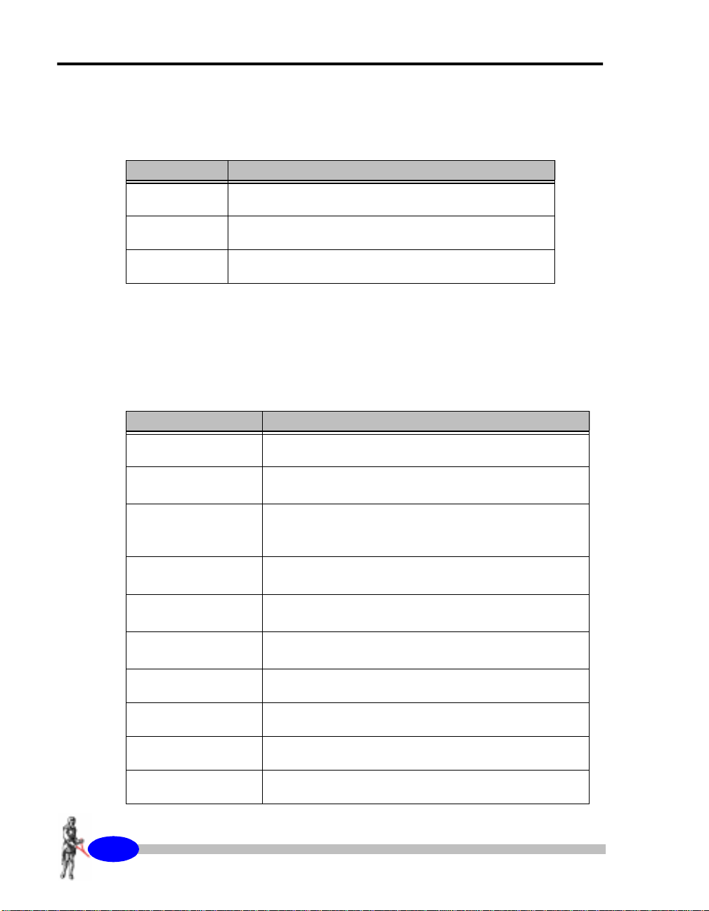
The following typeface conventions will be used throughout the manual.
Convention Use
Bold Italic
Indicates an action to be taken
Italic
ALL CAPS
Chapter layout
This manual i s divid ed into five chapt ers with the info rmation flow deta iled
in the following table.
Chapter Description
1. Getting Started
2. Setup
3. Operations
4.Maintenance
5.Reference
A.Offset Wenner
Technique
B.
Denotes a new term being introduced
Denotes the name of a method or mode
Gives an overview of the manual and the SARIS.
Describes how to setup your SARIS for a resistivity
survey.
Describes each step in a resistivity survey. Thorough
examples of a Schlumberger sounding and Wenner
profile are given
Describes basic maintenance, trouble-shooting and
basic repairs
Contains the technical specifications, instrument parts
list and warr anty information.
C.
D.
E.
405
SARIS Manual - part # 735700 Revision 1.1
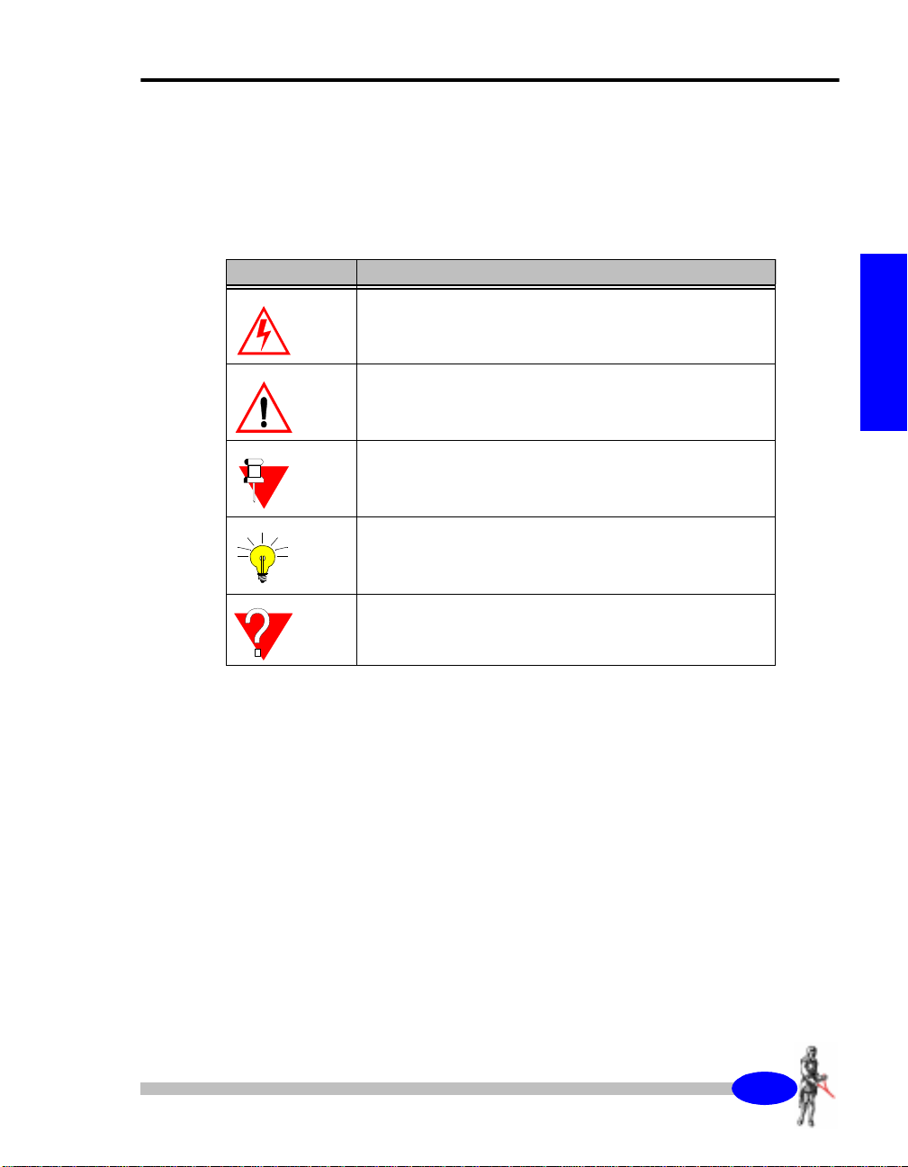
Symbols
The following symbols will be used to highlight specific sections of text
throughout the manual.
Symbol Meaning
About this manual
Warning:
Denotes an important point concerning safety
Important:
Indicates a important topic, particular attention should be
paid to this section
Note:
Denotes a point of interes t, or info rmatio n you s hould read
Tip:
Denotes an interesting hint for smoother operation
6WDUWXS
Question:
Indicates a relevant question concerning an important
topic
SARIS Manual - part # 735700 Revision 1.1
406
Getting Started
About the instrument
Important Safety Notice
Warning:
TX.
STOP
The SARIS can produce
touch current terminal A(C1) and B(C2) or any
NOT
bare wires or current electrodes while transmitting
current.
INJURIES.
Whereas Scintrex has taken reasonable precautions
in its design to minimize the possibility of personal
injury in its normal and proper use, Scintrex can
bear no responsibility in this regard.
All users are cautioned to establish and adhere
scrupulously to safe operating procedures in the
field, as well as safe practices in the maintenance
and repair of this unit.
It is recommended that all field operators be fully
advised of the potential hazard from these currents
and of the operating procedures necessary to avoid
accidents.
Positive communication between the operator and
all field personnel will help ensure that accidents do
not occur.
In case of an emergency, you can interrupt the
injection of current by pressing and holding the Tx
Stop key until an acknowledgement message
appears
THIS CAN RESULT IN SERIOUS
LETHAL
currents.
DO
407
SARIS Manual - part # 735700 Revision 1.1
This will shut down the transmitter and avoid
any further injuries.
Do not touch the electrodes or any section of bare
wire when the SARIS is injecting current.
Operation principles
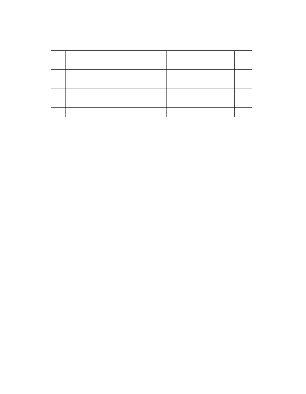
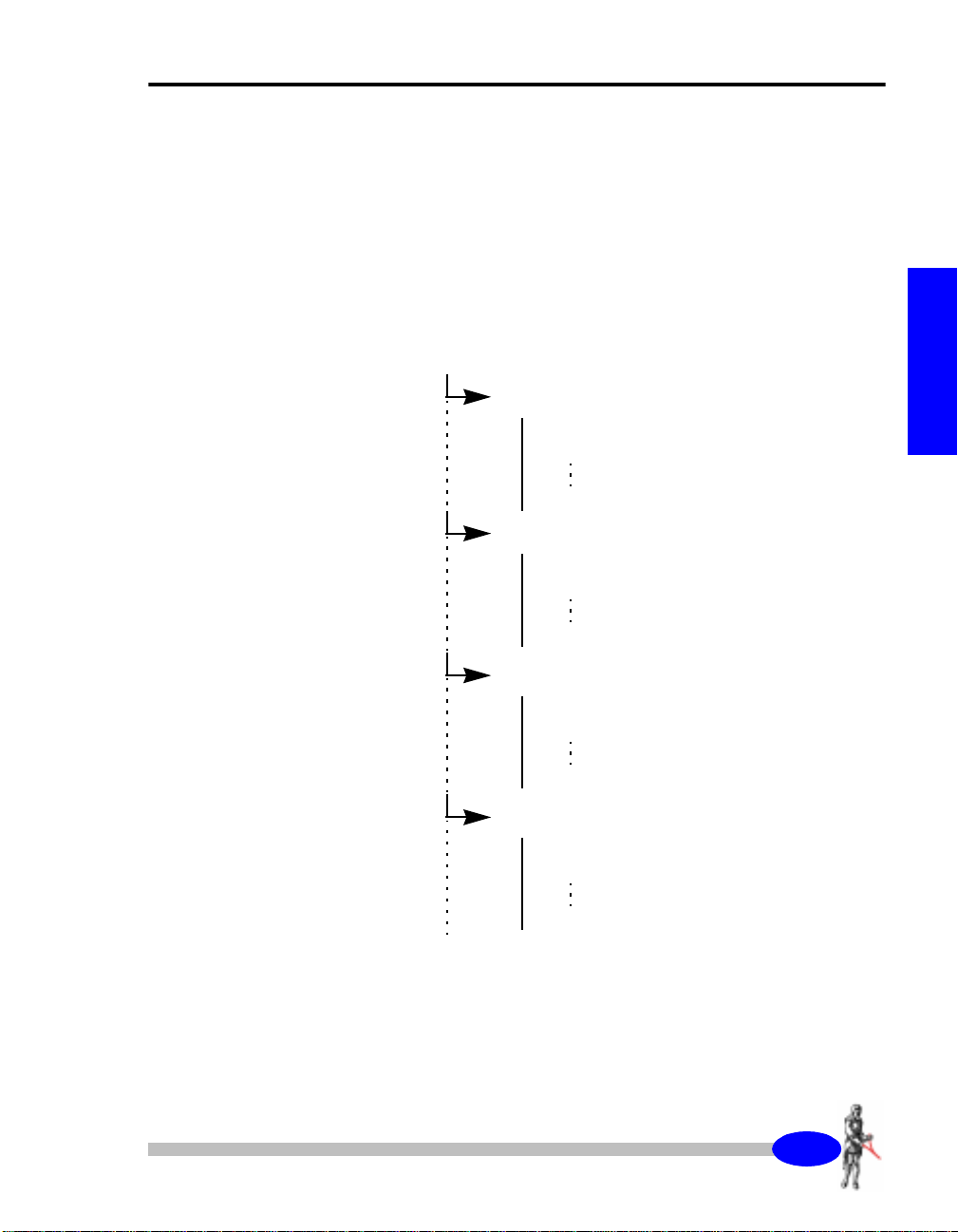
The SARIS has a structured database allowing you to enter as many surveys
as you want. You are only limited by the physical size of the memory, which
at 1008 Kilobytes will al low yo u to store more than a week’s worth of data in
your SARIS. Each survey is comprised of several soundings and/or profiles
that contain individual readings. The following flowchart illustrates how the
surveys ar e structure d in the memory.
Survey 1
About the instrument
6WDUWXS
Profile 1
readings
readings
readings
Profile 2
readings
readings
and so on.
readings
Sounding 1
readings
readings
readings
Profile 3
readings
readings
readings
408
SARIS Manual - part # 735700 Revision 1.1
Getting Started
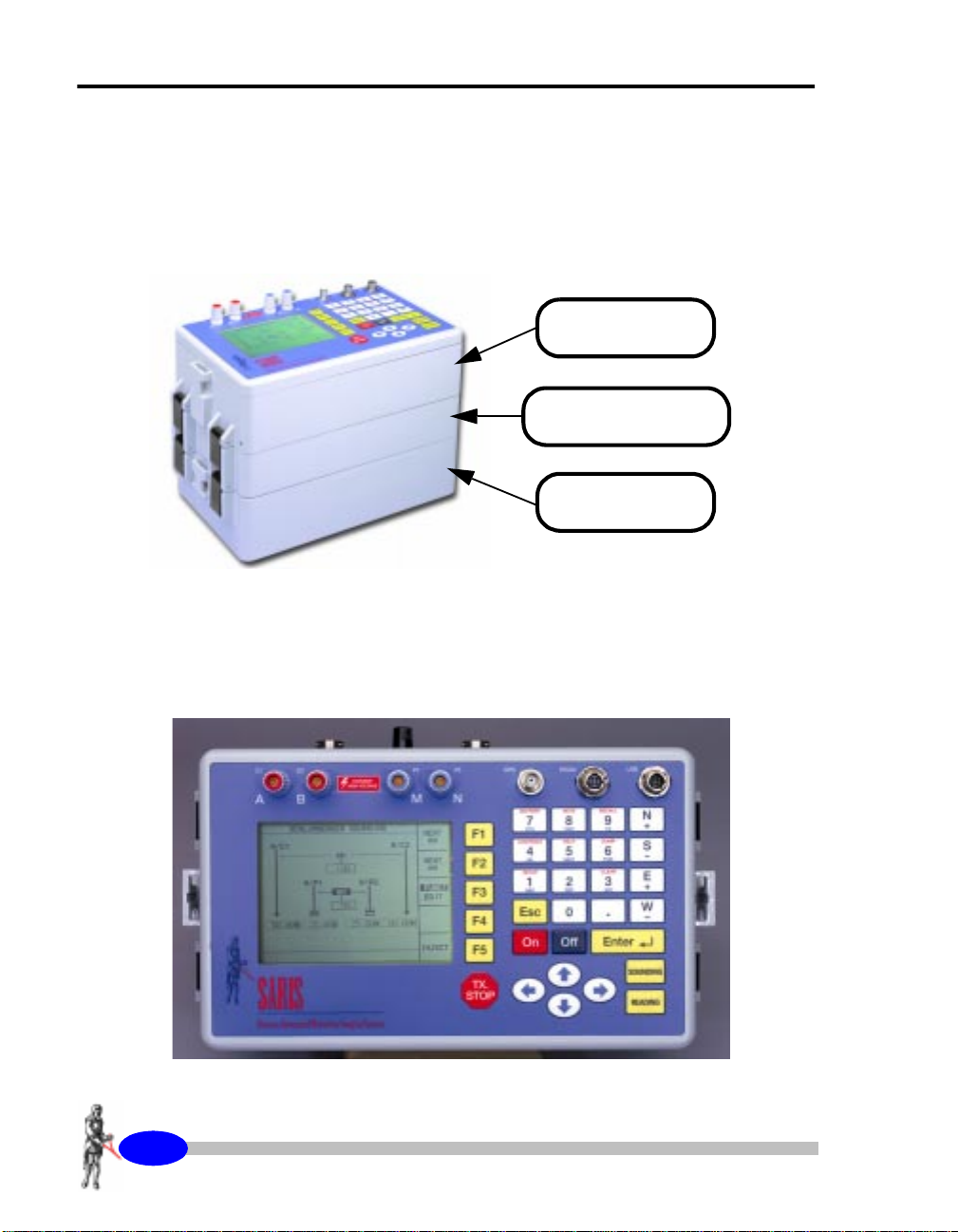
Instrument overview
The SARIS resistivity system consists of an electronics console, optional
multi-electrode or borehole interfaces which allow you to connect to
intelligent multi-electrode or borehole cables and a power supply module.
The following picture illustrates a SARIS system with a multi-electrode
interface.
Electronics
Console
Multi-Electrode
Cable Module
Power Supply
Module
Console and Keypad
The following picture shows the front panel of the console.
409
SARIS Manual - part # 735700 Revision 1.1
Keyboard description
About the instrument
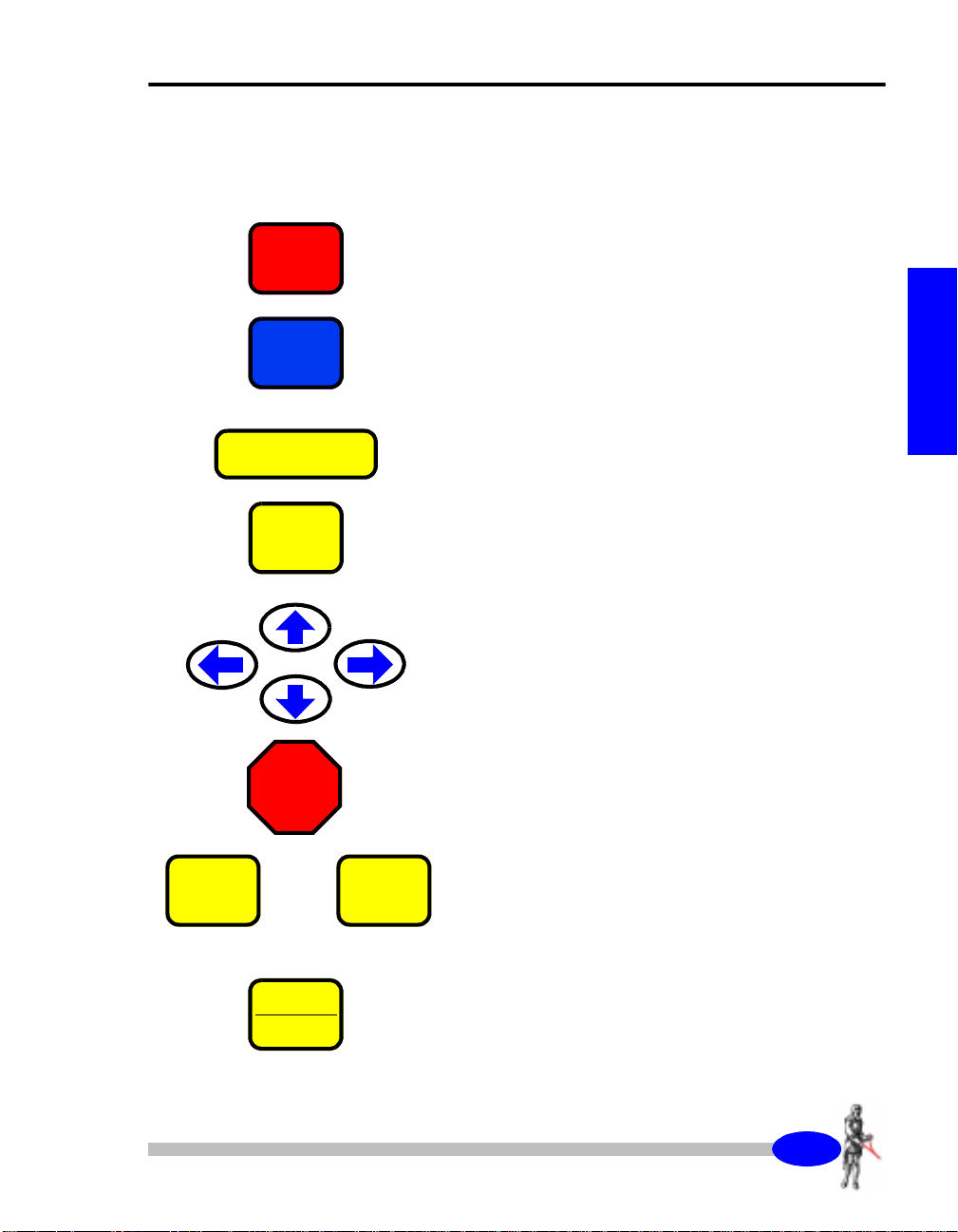
Function keys
On
Off
Enter
CXL
BKSP
TX.
STOP
↵↵↵↵
The On key turns the instrument on.
6WDUWXS
The Off key turns the instrumen t off.
The Enter key is used to acknowledge a particular
keystroke sequence. This is commonly used when
entering numeric parameters such as the value of the
AB spacing in a Schlumberger sounding.
The CANCEL key is used to either clear the data
field or to move the cursor back one space.
The arrow keys move the cursor either, right, left up
or down.
Emergency Stop:
Will immediately stop the injection of current.
F1
TO
SOUNDING
PROFILE
F5
The F1 to F5 function keys access the sub-menu
options. These options will vary according to the
current menu. For instance in the surveys screen the
F1 key allow you to access the parameters
sub-menu.
Press the Sounding/Profile key to begin a sounding
or a profile.
40:
SARIS Manual - part # 735700 Revision 1.1
Getting Started
READING
Starting a resistivity reading once a sounding or
profile has been properly set up.
Function/Alphanumeric keys
SETUP
1
ABC
SURVEY
2
DEF
MEMORY
3
GHI
CONTRAST
4
JKL
HELP
5
MNO
DUMP
6
PQR
INFO
7
STU
Keying in the number 1, letters a, b and c as well as
accessing the Setup screen.
Keying in the number 2, letters d, e and f as well as
accessing the Survey screen.
Keying in the number 3, letters g, h and i as well as
accessing the Memory screen.
Keying in the number 4, letters j, k and l as well as
accessing the Contrast Setting screen.
Keying in the number 5, letters m, n and o as well as
accessing the On-line help screen.
Keying in the number 6, letters p, q and r as well as
accessing the Dump screen.
Keying in the number 7, letters s, t and u as well as
accessing the Information screen.
NOTE
8
VWX
40;
SARIS Manual - part # 735700 Revision 1.1
Keying in the number 8, letters v, w and x as well as
accessing the Notes screen.
About the instrument
RECALL
9
YZ
N
.
S
0
E
.
W
0
Keying in the number 9, letters y and z as well as
accessing the Data Recall screen.
Direction/Sign keys
Keying in the nort h d ir ect io n, i n cr ea si ng t he contrast
and entering a + sign.
Keying in the south direction, decreasing the
contrast and entering a - sign.
Keying in the east direction, increasing the contrast
and entering a + sign.
Keying in the west direction, decreasing the contrast
and entering a - sign.
6WDUWXS
40<
SARIS Manual - part # 735700 Revision 1.1
Getting Started
Powering up the SARIS
PRESS
PRESS
On
CONTRAST
4
JKL
To turn your SARIS on,
Note:
If your SARIS does not turn on, or the screen is
either totall y blank o r dark, ple ase refer to “Trouble
shooting” on page 4-7.
press
the On key.
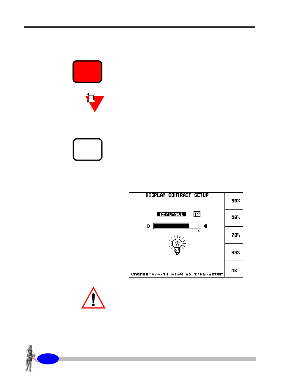
Adjusting the contrast
If the screen is either too dark or too light,
CONTRAST key.
The following screen will then appear.
press
the
4043
SARIS Manual - part # 735700 Revision 1.1
Important:
Polarizing sunglasses may prevent you from seeing
the screen, it will appear as all dark.
About the instrument
Preset contrast values
The preset contrast values are 30, 50 70 and 90%
contrast. The default value for the contrast is 50%.
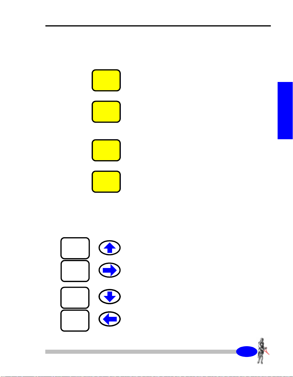
PRESS
PRESS
PRESS
PRESS
F1
F2
F3
F4
To set the contrast to 30%,
To set the contrast to 50%,
To set the contrast to 70%,
To set the contrast to 90%,
press
press
press
press
the F1 key.
the F2 key.
the F3 key.
the F4 key.
Manually set contrast values
The user can also manually set the contrast on a
scale of 1 to 16, from lighest to darkest.
6WDUWXS
N
.
E
.
S
0
W
0
To increase the contrast you can
keys illustrated on the left.
To decrease the contrast you can
keys illustrated on the left.
SARIS Manual - part # 735700 Revision 1.1
press
press
any of the
any of the
4044
Getting Started
PRESS
Press
the F5 key to exit the Contrast Adjustment
F5
screen.
4045
SARIS Manual - part # 735700 Revision 1.1
On-line display screens
In addition to the Contrast Screen previously described, there are two other
on-line display screens. These screens can be accessed at any time during the
operation of the SARIS.
About the instrument
PRESS
HELP
5
MNO
On-line help
The help key line allows you to access help topics
about the current screen being displayed.
To access the on-line Help screen,
key.
The screen that will then appear will depend on the
context in which the help key is pressed.
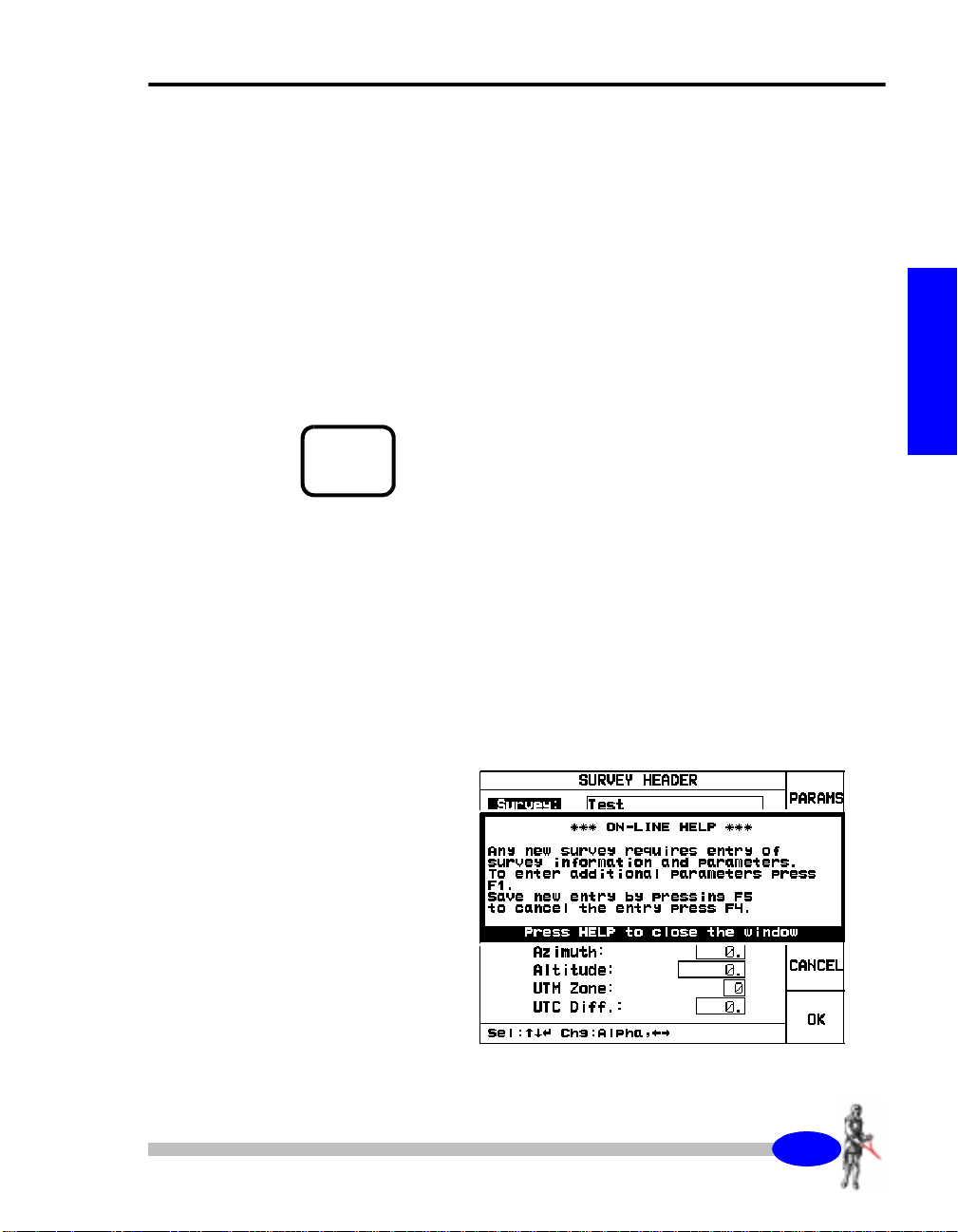
Example 1:
For instance, if the HELP key was pressed in the
Survey Screen (Survey key), the following screen
would appear as an overlay.
press
the HELP
6WDUWXS
4046
SARIS Manual - part # 735700 Revision 1.1
Getting Started
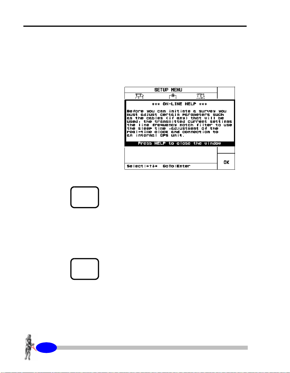
Example 2:
If the HELP key was pressed in the SetUp Screen
(SetUp key), the following screen would appear as
an overlay.
HELP
PRESS
PRESS
4047
SARIS Manual - part # 735700 Revision 1.1
5
MNO
INFO
7
STU
To exit the on-line help
press
the HELP/5/MNO key
to return to the previous screen.
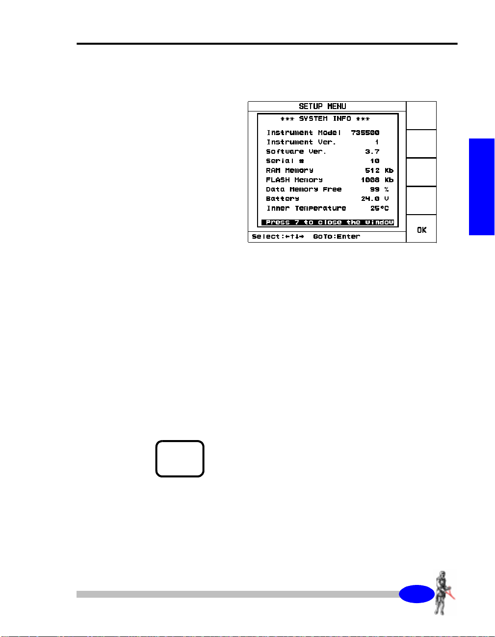
System information
The information on-line screen presents information
about your SARIS.
To show the on-line information screen,
INFO key.
press
the
About the instrument
The following screen will then appear as an overlay
to the screen being presently displayed.
The informat ion topics illustrat ed on the screen are
in order:
•
Instrument model number,
•
Instrument version,
•
Software version,
•
Serial number,
•
Quantity of RAM available,
•
Quantity of flash memory available
•
Percentage of free memory,
•
Battery voltage
•
Inner temperature of the unit.
6WDUWXS
PRESS
INFO
7
STU
Press
the INFO key to return t o the previous screen.
SARIS Manual - part # 735700 Revision 1.1
4048
Getting Started
Keyboard operations
There are several basic keyboard operations that will be repeated throughout
the manual. These operations are as follows:
For purposes of clarity and briefness, we shall enumerate these procedures
only once. Where in the manual these procedures are called upon, we shall
refer to the present sec tion.
Entering values in fields
There are two types of parameter fields:
•
Fields with preset values.
•
Fields with no preset values.
As a general example, let us consider a screen that has both types of fields.
In the Transmitter SetU p scree n, you can selec t the opera ting opt ions for the
transmitted current.
•
entering v alues in field,
•
editing fields,
•
entering alphanumeric values.
SETUP
PRESS
4049
SARIS Manual - part # 735700 Revision 1.1
1
ABC
With the SARIS turned on,
access the Set-Up screen.
press
the SETUP key to
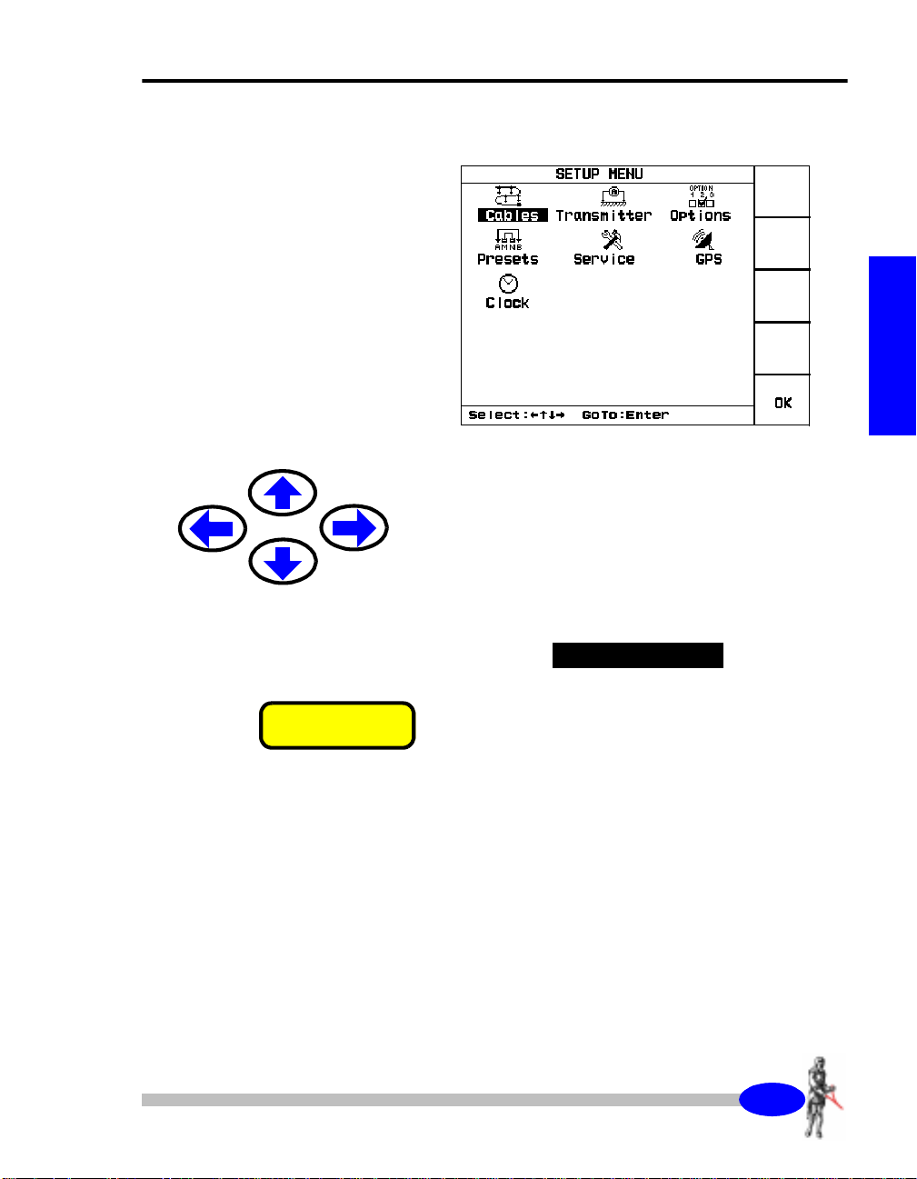
About the instrument
The following screen will then appear.
Press
the arrow keys to bring your cursor to the
transmitter icon.
6WDUWXS
PRESS
Enter
↵↵↵↵
The word Transmitter will then be highlighted, as
illustrated below.
7UDQVPLWWHU
Press
the Enter ke y.
404:
SARIS Manual - part # 735700 Revision 1.1
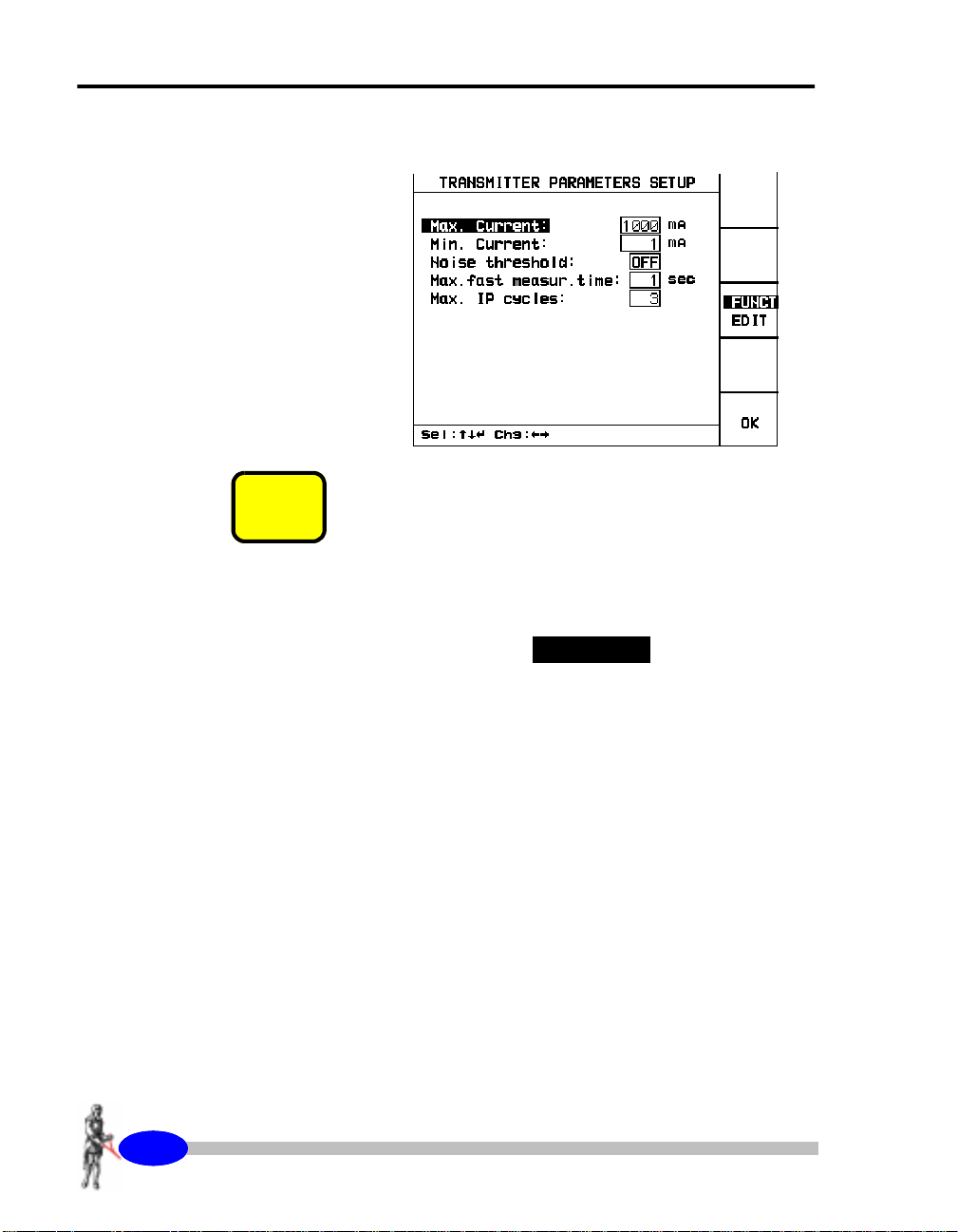
Getting Started
The following screen will then appear.
PRESS
F3
Press
the F3 key to toggle between the Function
mode and the edit mode.
When in the EDIT mode, the word EDIT will be
highlighted, as illustrated below.
(',7
404;
SARIS Manual - part # 735700 Revision 1.1

About the instrument
Fields with preset values
Press
the up or down arrow keys to bring your
cursor to the maximum current parameter.
PRESS
SURVEY
2
DEF
0D[1#&XUUHQW=
Press
the right o r left arrow key to set the value of
the maximum current. The preset values are 50, 100,
200, 500, 750 or 1000 mA.
Alphanumeric entry, example 1
The alphanumeric keys allow you to enter four
characters per key. The entered character depends
on the number of times the key is pressed. For
instance as you toggle the 2/DEF key you will
successively obtain 2, d, e or f
Press
the up or down arrow keys to bring your
cursor to the maximum measurement time
parameter.
0D[#0HDVXU1#WLPH=
Key in the value. For instance for 20
press
the 2 key,
6WDUWXS
PRESS
PRESS
0
Enter
↵↵↵↵
and then
Press
press
the 0 key.
the Enter key to acknowledge your choice.
SARIS Manual - part # 735700 Revision 1.1
404<

Getting Started
PRESS
Press
the F5 key to return to the SETUP screen.
F5
Alphanumeric entry, example 2
PRESS
SURVEY
2
DEF
With the SARIS turned on,
to access the Survey Header screen.
The following screen will then appear.
Press
the up or down arrow keys to bring your
cursor to the Survey parameter.
The Survey parameter will then be highlighted as
illustrated below.
press
the SURVEY key
6XUYH\=
PRESS
4053
SARIS Manual - part # 735700 Revision 1.1
F3
Press
the F3 key to toggle between the function
mode and edit mode.
When in the EDIT mode, the word EDIT will be
highlighted as illustrated below,
(',7

About the instrument
and the flashi ng c ur sor will mo ve into the data fie ld,
as illustrated below.
6XUYH\=
5
HG#5LYHU
PARAMETER DATA FIELDDATA FIELD
PRESS
PRESS
PRESS
PRESS
F2
F1
INFO
7
STU
F1
To enter a new survey name,
will clear the data field.
Key in the desired survey name, this can be any
alphanumeric value up to 19 characters long.
For instance, if you were to write Test as the survey
name, you would first
LOCK is on, in order to get uppercase characters, as
illustrated below.
press
press
the F2 key. This
the F1 key unt il CAPS
&$36
/2&.
RQ
press
Then
To return to lowercase,
toggle back to lowercase characters, CAPS LOCK
will then be set to off, as illustrated below.
the STU key until you obtai n th e l ett er T.
RII
press
the F1 key again to
&$36
/2&.
RQ
RII
6WDUWXS
PRESS
To advance your cursor,
SARIS Manual - part # 735700 Revision 1.1
press
the right arrow key.
4054

Getting Started
PRESS
SURVEY
Press
2
DEF
the 2/DEF key until you obtain the letter e.
PRESS
PRESS
PRESS
PRESS
PRESS
PRESS
INFO
7
STU
INFO
7
STU
Enter
F3
↵↵↵↵
Press
the right arrow key to advance your cursor.
Press
the 7/STU key until you obtain the letter s.
Press
the right arrow key to advance your cursor.
Press
the 7/STU key until you obtain the letter t.
Press
the ENTER key to acknowledge your choice.
When you are finished editing the parameter,
the F3 key to exit the EDIT mode.
press
4055
SARIS Manual - part # 735700 Revision 1.1

Your survey
The SARIS can be configured to suit your many needs. In order to optimize
your survey you must first determine if either a sounding or profile are the
appropriate survey methods to be used.
A sounding would be carried out if you would to get vertical resistivity
information at a giv en point, wher eas an i magi ng surve y would be c arried out
to get two-dimensional information of the sub-surface.
Furthermore, the SARIS can be configured to carry out soundings and
profiles automatically with the help of the Automated Sounding Cables, as
illustrated below.
Your survey
6WDUWXS
Sounding configuration
The following electrode arrays can be used for soundings:
•
•
•
•
Schlumberger
Wenner
Offset Wenner
Dipole-dipole
4056
SARIS Manual - part # 735700 Revision 1.1

Getting Started
A
.
I
V
na
M
N
na
B
a
The Schlumberger electrode array
I
V
A
M
a
N
a
a
The Wenner electrode array
1. For a complete description of the Offset Wenner Array, see Appendix A,
4057
SARIS Manual - part # 735700 Revision 1.1
B
1
“Offset Wenner Sounding”
.

Your survey
V
NP1P2
a
M
The dipole-dipole electrode array
Profiling configuration
The following electrode arrays can be used for profiling:
•
•
•
•
•
•
•
A
na
C1
Schlumberger
Wenner
Dipole-dipole
Pole-dipole
Axial Pole-pole
Lateral Pole -pole
Gradient
I
C2
a
B
6WDUWXS
4058
SARIS Manual - part # 735700 Revision 1.1

Getting Started
∞
N
NP1P2
P2
V
a
M
The Pole-dipole electrode array
na
A
C1
V
M
P1
The Axial Pole-pole electrode array
na
A
C1
B
∞
I
C2
a
B
∞
I
C2
4059
SARIS Manual - part # 735700 Revision 1.1

Your survey
∞
N
P2
P1
V
M
A
C1
P1
V
The lateral P ole-pole electrode array
P2
N
M
C1
A
∞
6WDUWXS
B
∞
I
C2
∞
B
C2
I
The Gradient electrode array
SARIS Manual - part # 735700 Revision 1.1
405:

Getting Started
Automated soundings and profiles
As mentioned previously, resistivity surveys can be fully automated with the
use of the intelligent cables.
The survey cables which are commonly available are the following:
SCS-64 Wenner Sounding
SCS-128 Wenner Sounding
SCS-256 Wenner Sounding
SCS-96 Wenner & Schlumberger Sounding
SCS-192 Wenner & Schlumberger Sounding
SCS-384 Wenner & Schlumberger Sounding
ICS-1 Imaging/Profiling
ICS-2 Imaging/Profiling
ICS-3 Imaging/Profiling
ICS-5 Imaging/Profiling
ICS-10 Imaging/Profiling
ICS-12.5 Imaging/Profiling
ICS-15 Imaging/Profiling
ICS-20 Imaging/Profiling
Furthermore, Scintrex can custom build and type of cable to fit your own
specific requirements.
405;
SARIS Manual - part # 735700 Revision 1.1

Dumping data
Important:
The SCTUTIL Scintrex Utilities program that is
supplied along with your SARIS must be installed t o
allow you to transfer data from your SARIS. Please
refer to “Installing SCTUTIL” on page C-2 for
further instructions.
Dumping data in USB
Important:
In order for you to transfer data from your SARIS
using the USB mode, you have the following in your
PC:
Dumping data
6WDUWXS
•
USB Port
•
USB Host Driver
Mimimum system requirements
Important:
The SCTUTIL Scintrex Utilities program
function in a Windows 3.x environment
The Minimum requirements for your PC are as
follows:
•
WINDOWS 95 or better
•
8 MB of RAM
•
3 MB of Hard Disk space
SARIS Manual - part # 735700 Revision 1.1
will not
.
405<

Getting Started
Resetting the SARIS
Important:
Should your SARIS lock-up, i.e. that it does not
respond to any keystroke,
PRESS
Off
press
the OFF key
hold
and
The instrument will then reset itself. However, your
data
for approximately five seconds.
will not
be lost.
Resetting the default parameters
Important:
In the extremely rare event that your database
becomes corrupted, ( also see “Trouble shooting” on
page 4-7), you will have to reset your SARIS to the
PRESS
TX.
STOP
default parameters.
entirely your data, list of cables and presets .
To reset the SARIS to the default paramete rs:
First, shut the SARIS off by pressing the Off key
press
the Tx Stop
However, this will erase
AND
PRESS
4063
SARIS Manual - part # 735700 Revision 1.1
On
and
On keys together. The unit will then reset itself to
the default parameter setting and all data, list of
cables and presets will be erased.

4
2
Set-up screen
Before you can initiate a resistivity survey, you must adjust certain
parameters such as the cables (if any) that will be used, the transmitted
current settings, the line frequency notch filter to use, the sleep time,
adjustment of the real-time clock, and connection to an internal GPS unit.
SETUP
PRESS
1
ABC
Instrument Setup
Press
the SETUP key to access the Setup screen.
6HWXS
50
4
SARIS Manual - part # 735700 Revision 1.1

Instrument Setup
Cable setup
The Cable screen allows you t o choo se which imaging or sounding cable that
you want to use.
The following screen will then appear.
PRESS
505
SARIS Manual - part # 735700 Revision 1.1
Enter
↵↵↵↵
In the Setup screen,
press
the arrow keys to bring
your cursor to the cables icon.
The word Cables will then be highlighted, as
illustrated below.
&DEOHV
Press
the Enter key to access the cables screen.

Set-up screen
The following screen will then appear.
You have then the choice to either select a cable, read a new cable, delete an
existing cable from the list of available cables or copy an existing cable for
editing.
6HWXS
506
SARIS Manual - part # 735700 Revision 1.1

Instrument Setup
Selecting a cable
When your power up your SARIS and if you have a
multi-electrode cable module in place, it will
automatically recognize the cable connected to it
and enter th e cable and its pa rameters in the li st of
available cables . I f your cable is not con nected to the
module you can also detect this cable (see
“Detecting a new cable” on page 2-7).
PRESS
Enter
↵↵↵↵
In the Cable Setup screen,
press
the arrow keys to
bring your cursor to the Select icon.
The word Select will then be highlighted, as
illustrated below.
6HOHFW
Press
the Enter key to access the cable list screen.
The following screen will then appear.
507
SARIS Manual - part # 735700 Revision 1.1

Set-up screen
Press
the up or down arrow keys to bring the cursor
to the chosen cable.
The cable will then be highlighted as illustrated
below.
,&604#,PDJLQJ
PRESS
PRESS
F4
F3
To select this cable,
The cable will then be selected as illustrated below.
press
the F4(SELECT) key.
,&604#,PDJLQJ
To show the parameters of this cable,
F3(SHOW) key.
The following screen will then appear.
press
the
6HWXS
508
SARIS Manual - part # 735700 Revision 1.1

Instrument Setup
Important:
You cannot edit cable parameters, these are
illustrated for information purposes only.
PRESS
F5
To exit the Cable Parameters screen,
F5(OK) key to return to the Cable List screen.
Once the selection is acceptable,
key to return to the Cable screen.
press
press
the F5(OK)
the
509
SARIS Manual - part # 735700 Revision 1.1

Set-up screen
Detecting a new cable
During the course of your survey, you may want to
add a new cable to the list of available cables.
Note:
If you turn your SARIS on and a cable is already
connected to your multi-electrode cable module, the
SARIS will automatically recognize this cable and
its parameters in the list of available cables.
PRESS
PRESS
Enter
Enter
↵↵↵↵
↵↵↵↵
In the Cable screen,
your cursor to the New icon.
The word New will then be highlighted, as
illustrated below.
press
the arrow keys to bring
'HWHFW
Connect
module.
Press
You wi ll th en be w arn e d th at th e c a bl e w as ad de d to
the list of available cables. To view the list of
available cables, see “Selecting a cable” on
page 2-4.
Press
to the Cable screen.
your new cable to the multi-electrode cable
the Enter key to access the new cable screen.
the Enter key to close this window and return
6HWXS
50:
SARIS Manual - part # 735700 Revision 1.1

Instrument Setup
Deleting a cable
PRESS
Enter
↵↵↵↵
In the Cable screen,
press
the arrow keys to bring
your cursor to the Delete icon.
The word Delete will then be highlighted, as
illustrated below.
'HOHWH
Press
the Enter key to access the cable del ete scree n.
The following screen will then appear.
50;
SARIS Manual - part # 735700 Revision 1.1
Press
the up or down arrow keys to bring the cursor
to the chosen cable.

Set-up screen
The cable will then be highlighted as illustrated
below.
,&604#,PDJLQJ
PRESS
F4
To select this cable,
The cable will then be selected as illustrated below.
And the following screen will then appear.
Note:
press
the F4(SELECT) key.
,&604#,PDJLQJ
6HWXS
PRESS
PRESS
F4
F5
If you marked the wrong cable by mistake, you can
always unmark a cable by pressing the F3(MARK)
key again.
To delete this cable,
Once the selection is acceptable,
key to return to the Cable screen.
press
the F4(DELETE) key.
press
the F5(OK)
50<
SARIS Manual - part # 735700 Revision 1.1

Instrument Setup
Copying a cable
When you are daisy-chaining imaging cables, i.e.
connecting several imaging cables end to end, you
will find it much more practical to create a new
virtual cable comprising the totality of all the
electrodes on the daisy-chained cables.
What is a virtual cable?
A virtual cable is a list of electrode positions. A
virtual cable is treated like a real cable in the sense,
but does not exist in a physical sense. For a detailed
example on how to create a virtual cable, see
“Creating a virtual cable, example 1” on page 2-15.
Hint:
When you are modifying your cable separation, i.e.
using a smaller separation than the standard
separation of your standard imaging cable, you will
find it much more practical to create a new virtual
cable indicating the new electrode separation.
PRESS
5043
SARIS Manual - part # 735700 Revision 1.1
Enter
↵↵↵↵
In the Cable screen,
press
the arrow keys to bring
your cursor to the Copy icon.
The word Copy will then be highlighted, as
illustrated below.
&RS\
Press
the Enter ke y.

Set-up screen
The following screen will then appear.
Press
the up or down arrow keys to bring the cursor
to the chosen cable.
The cable will then be highlighted as illustrated
below.
,&604#,PDJLQJ
6HWXS
PRESS
F4
To copy this cable,
The following screen will then appear.
press
the F4(COPY) key.
SARIS Manual - part # 735700 Revision 1.1
5044

Instrument Setup
Press
the up or down arrow keys to bring the cursor
to the chosen parameter you wan t to edit.
PRESS
PRESS
F3
F2
Press
the F3(FUNCT/EDIT) key to choose the
EDIT mode.
1DPH=
Press
the F2(CLEAR ALL) key to clear the name
field.
Enter
the cable name as an alphanumeric value; this
can be up to 19 characters long.
Please refer to “Alphanumeric entry, example 2” on
page 1-20 if you are unsure of the procedure.
7\SH=
You can choose either Imaging or Sounding as your
cable type.
Press
the right or left arrow key to toggle between
sounding and imaging.
5045
SARIS Manual - part # 735700 Revision 1.1
Important:
You cannot edit your type of cable. This is indicated
for information purposes only. All other cable
parameters are fully editable.

Set-up screen
1R1HOHFWURGHV=
The number of electrodes a cable has refers to the
number of takeouts on the cable. In the case of two
25 takeout cable which are dai sy-ch ained e nd to e nd,
the total number of electrodes will then be 50
electrodes.
Enter
the number of electrodes as a numeric
parameter. Please refer to “Alphanumeric entry,
example 1” on page 1-19, if you are unsure of the
procedure.
6HFWLRQ=
The number of sections usually depends on the type
of cable: for instance a sounding will always need
two cable sections because the sounding point is
always in the center of the array. For imaging, the
user can employ either one or two cables.
6HWXS
Important:
For the time being, only one-section imaging is
supported.
Press
the right or left arrow key to toggle between
one or two sections.
You will also notice the following icons appearing
besides the number of sections:
For one section.
5046
SARIS Manual - part # 735700 Revision 1.1

Instrument Setup
For two sections.
6SDFLQJ=
The base spacing between the electrodes can be set
to any number as long as it is compatible with your
cable. This value can be set from 0.1 to 10000.
Hint:
You can use a smaller spacing with any imaging
cable. Remember, however, to measure your
electrode spacing precisely, otherwise your apparent
resistivities could be erroneous.
Enter
the electrode spacing as a numeric parameter.
Please refer to “Alphanumeric entry, example 1” on
page 1-19, if you are unsure of the procedure.
PRESS
PRESS
PRESS
5047
SARIS Manual - part # 735700 Revision 1.1
F3
F5
F5
8QLWV=
The units will be either in metres or in feet.
Press
the right or left arrow key to toggle between
meter and feet.
Press
the F3(FUNCT/EDIT) key to exit the EDIT
mode.
Once the cable parameter values are acceptable,
press
the F5(SAVE) key to accept them, save the
new cable and to return to the cable list screen.
Press
the F5(CANCEL) key to exit to cable screen.

PRESS
SETUP
1
ABC
Set-up screen
Press
the SETUP key to return to the Set-Up screen.
Creating a virtual cable, example 1
As mentioned earlier, when you are daisy-chaining
imaging cables, i.e. connecting several imaging
cables end to end, you will find it much more
practical to create a new virt ual cab le compri sing t he
totality of all the electrodes on the daisy-chained
cables.
The following example illustrates a typical example
of a virtual cable. Where a two standard ICS-1
cables with 25 takeout s e ach are daisy-chained and a
virtual cable containing 50 electrodes is created.
6HWXS
PRESS
Enter
↵↵↵↵
In the Cable screen,
your cursor to the Copy icon.
The word Copy will then be highlighted, as
illustrated below.
press
the arrow keys to bring
&RS\
Press
the Enter ke y.
5048
SARIS Manual - part # 735700 Revision 1.1

Instrument Setup
The following screen will then appear.
Press
the up or down arrow keys to bring the cursor
to the chosen cable.
The cable will then be highlighted as illustrated
below.
,&604#,PDJLQJ
PRESS
5049
SARIS Manual - part # 735700 Revision 1.1
F4
To copy this cable,
press
the F4(COPY) key.

Set-up screen
The following screen will then appear.
Press
the up or down arrow keys to bring the cursor
to the chosen parameter you want to edit.
6HWXS
PRESS
PRESS
F3
F2
Press
the F3(FUNCT/EDIT) key to choose the
EDIT mode.
1DPH=
Press
the F2(CLEAR ALL) key to clear the name
field.
Enter
the cable name “ICS-1 50 electrodes” as an
alphanumeric value.
Please refer to “Alphanumeric entry, example 2” on
page 1-20 if you are unsure of the procedure.
504:
SARIS Manual - part # 735700 Revision 1.1

Instrument Setup
7\SH=
You will not change the type, it will remain as an
imaging cable.
Press
the right or left arrow key to toggle between
sounding and imaging.
Important:
You cannot edit your type of cable. This is indicated
for information purposes only. All other cable
parameters are fully editable.
1R1HOHFWURGHV=
The number of electrodes a cable has refers to the
number of takeouts on the cable. In the case of two
25 takeout cable which a re dai sy-cha ined e nd to en d,
the total number of electrodes will then be 50
electrodes.
504;
SARIS Manual - part # 735700 Revision 1.1
Enter
the number of electrodes (50) as a numeric
parameter. Please refer to “Alphanumeric entry,
example 1” on page 1-19, if you are unsure of the
procedure.
6HFWLRQ=
The number of sections usually depends on the type
of cable: for instance a sounding will always need
two cable sections because the sounding point is
always in the center of the array. In this case you
will be using one section of cables.
Important:
For the time being, only one-section imaging is
supported.

Set-up screen
Press
the right or left arrow key to toggle between
one or two sections.
You will also notice the following icons appearing
besides the number of sections:
For one section.
For two sections.
6SDFLQJ=
The base spacing between the electrodes can be set
to any number as long as it is compatible with your
cable. This value can be set from 0.1 to 10000.
6HWXS
Hint:
You can use a smaller spacing with any imaging
cable. Remember, however, to measure your
electrode spacing precisely, otherwise your apparent
resistivities could be erroneous.
Enter
the electrode spacing as a numeric parameter.
Please refer to “Alphanumeric entry, example 1” on
page 1-19, if you are unsure of the procedure.
8QLWV=
The units will remain as metres.
Press
the right or left arrow key to toggle between
meter and feet.
504<
SARIS Manual - part # 735700 Revision 1.1

Instrument Setup
PRESS
F3
Press
the F3(FUNCT/EDIT) key to exit the EDIT
mode.
Your edit cable screen should resemble the
following.
PRESS
5053
SARIS Manual - part # 735700 Revision 1.1
F5
Once the cable parameter values are acceptable,
press
the F5(SAVE) key to accept them, save the
new virtual cable and to return to the cable list
screen.

Set-up screen
When you return to the Cable Select menu (see
“Selecting a cable” on page 2-4), you will notice
that your virtual cable is in the list of available
cables, as illustrated below.
You can now select it as any other cable.
6HWXS
5054
SARIS Manual - part # 735700 Revision 1.1

Instrument Setup
Transmitter screen
The transmitter screen allows the user to select the operating options for the
transmitted current.
PRESS
Enter
↵↵↵↵
In the Setup screen,
press
the arrow keys to bring
your cursor to the transmitter icon.
The word Transmitter will then be highlighted, as
illustrated below.
7UDQVPLWWHU
Press
the Enter ke y.
The following screen will then appear.
5055
SARIS Manual - part # 735700 Revision 1.1

Set-up screen
Press
the up or down arrow keys to bring the cursor
to the chosen parameter you want to edit.
PRESS
F3
Press
the F3(FUNCT/EDIT) key to choose the
EDIT mode.
0D[1#&XUUHQW=
0D[1#&XUUHQW=
The approximate maximum current value that you
will be able to inject can be set to values of 50, 100,
200, 500, 750 and 1000mA.
Press
the right o r left arrow key to set the value of
the maximum current.
0LQ1#&XUUHQW=
In all instances, the SARIS will inject the minimum
current possible, while still preserving the utmost
data quality, in order to preserve battery power. You
can also override this feature by setting a minimum
current value which is higher than the SARIS would
normally inject.
The approximate minimum current value that you
will be able to inject can be set to values of 1, 2, 5,
10, 20, 50, 100, 200, 500, 750 and 900 mA.
6HWXS
Press
the right o r left arrow key to set the value of
the minimum current.
SARIS Manual - part # 735700 Revision 1.1
5056

Instrument Setup
Note:
The SARIS will use approximate values for the
current. You may very well have a current value
slightly under the selected minimum.
1RLVH#WKUHVKROG=
The noise threshold is understood as the maximum
variance of signal. The number of cycles that the
measurement will take wil l depe nd on th is thr eshol d.
The lower the threshold and higher the ambient
electrical noise, the longer the measurement will
take until it is acceptable.
The threshold can be set to OFF, LOW, M ED or HI.
These thresholds respectively correspond to
maximum variance values of 0, 0.01, 0.1 and 0.5.
Press
the right o r left arrow key to set the value of
the noise threshold.
5057
SARIS Manual - part # 735700 Revision 1.1
0D[1#IDVW#PHDVXU1#WLPH=
The maximum fast measurement time parameter
determines what maximum length of time the unit
will carry out a resistivity measurement for each
reading.
Enter
the maximum m easurement time as a numeric
parameter. Please refer to “Alphanumeric entry,
example 1” on page 1-19, if you are unsure of the
procedure.

Set-up screen
0D[1#,3#F\FOHV=
The maximum number of IP cycles determines what
maximum number of full cycles (ex. 8 seconds for a
2 sec cycle) the unit will carry out a resistivity/IP
measurement for each reading.
Enter
the maximum number of IP cycles as a
numeric parameter. The maximum number of IP
cycles can be set from 3 to 100. Please refer to
“Alphanumeric entry, example 1” on page 1-19, if
you are unsure of the procedure.
Note:
The noise threshold always has precedence over any
other setting, either the maximum fast measurement
time or the maximum number of IP cycles.
Therefore, the measurement will stop when the
noise threshold is attained before either the
maximum fast measurement time or the maximum
number of IP cycles.
6HWXS
PRESS
PRESS
F3
F5
Hint:
If you want your SARIS to carry out the maximum
number of IP cycles without stopping because of the
noise threshold, set this threshold to 0.
Press
the F3(FUNCT/EDIT) key to exit the EDIT
mode.
After you are satified with the chosen transmitter
parameter values,
them and to return to the Setup menu.
press
the F5(OK) key to accept
5058
SARIS Manual - part # 735700 Revision 1.1

Instrument Setup
Options screen
The options screen allows you t o selec t four opt ions: the lin e frequ ency notc h
filter, the sleep time , whether to fla g the warnings.
PRESS
Enter
↵↵↵↵
In the setup screen,
press
the arrow keys to bring the
cursor to the options icon.
The word Options will then be highlighted, as
illustrated below.
2SWLRQV
Press
the Enter ke y.
The following screen will then appear.
5059
SARIS Manual - part # 735700 Revision 1.1

PRESS
F3
Set-up screen
Press
the F3(FUNCT/EDIT) key to choose the
EDIT mode.
/LQH+PDLQV,#IUT=
You have the choice between 60 and 50 Hz notch
filters.
Press
the right or left arrow key to select the power
line frequency of the area in which your SARIS is
being used.
6OHHS#DIWHU=
You can choose to have the unit turn itself off if no
keys are pressed after 1, 2, 5, 10, 20 or 30 minutes.
Furthermore, if you choose NO, the unit will not
turn itself off unless you do so by pressing the OFF
key.
6HWXS
Press
the right or left arrow key to toggle between
values.
6FDQ#:DUQLQJV=
You can have your SARIS warn you if there are bad
contacts or open loops when using intelligent
electrode cables. The unit wi ll the automat ically s top
to allow you to verify the contacts or connect the
appropriate electrode.
Press
the right or left arrow key to toggle between
YES and NO.
505:
SARIS Manual - part # 735700 Revision 1.1

Instrument Setup
2II:HQQHU#LQWHUSRO1=
You can have your SARIS calculate the Wenner
intermediary points when you are performing Offset
Wenner Soundings. For more information, see
Appendix A "Offset Wenner Sounding".
Press
the right or left arrow key to toggle between
YES and NO.
PRESS
F5
Press
the F5(OK) key to return to the SETUP menu.
505;
SARIS Manual - part # 735700 Revision 1.1

Presets setup
The presets menu allows you to choose a preset list of electrode positions.
This is most convenient in the sounding mode, when you are not using a
sounding cable. Thus, the preset positions can be thought of as a virtual
sounding cable. Furthermore, the presets are applicable while performing
Wenner and Schlumberger soundings.
Set-up screen
Note:
Presets have no use in imaging. An imaging cable
has takeouts at constant intervals, therefore using a
preset list of positions in imaging is redundant; the
next position is attained simply by incrementing
from the keypad.
6HWXS
PRESS
Enter
↵↵↵↵
In the Setup screen,
your cursor to the presets icon.
The word Presets will then be highlighted, as
illustrated below.
press
the arrow keys to bring
3UHVHWV
Press
the Enter key to access the presets menu.
505<
SARIS Manual - part # 735700 Revision 1.1

Instrument Setup
You have then the choice to either select a preset already created, create a
new preset, delete an existing preset from the list of available presets or copy
an existing p reset for edit ing.
The following screen will then appear.
5063
SARIS Manual - part # 735700 Revision 1.1

Set-up screen
Creating a new preset
During the course of your survey, you may want to
create a new preset list of electrode positions.
PRESS
Enter
↵↵↵↵
In the Preset screen,
your cursor to the New icon.
The word New will then be highlighted, as
illustrated below.
press
the arrow ke ys to bring
1HZ
Press
the Enter ke y.
The following screen will then appear.
6HWXS
5064
SARIS Manual - part # 735700 Revision 1.1

Instrument Setup
You will then be prompted to enter the name of your
new preset list of positions, its type and the number
of points in the preset list.
Note:
You will already be in the edit mode, therefore there
will be no need to press the F3(FUNCT/EDIT) key
to access the edit mode.
Press
the up or down arrow keys to bring the cursor
to the chosen parameter you wan t to edit.
1DPH=
PRESS
5065
SARIS Manual - part # 735700 Revision 1.1
F2
Press
the F2(CLEAR ALL) key to clear the name
field.
Enter
the preset name as an alphanumeric value;
this can be up to 19 characters long.
Please refer to “Alphanumeric entry, example 2” on
page 1-20 if you are unsure of the procedure.
7\SH=
You can choose either Wenner or Schlumberger as
your sounding type.
Press
the right or left arrow key to toggle between
:(11(5 and 6&+/80.

PRESS
F1
Set-up screen
1R1SRLQWV=
The number of points on a preset refers to the
number of electrode positions in the preset list.
Enter
the number of electrode positions as a
numeric parameter. Please refer to “Alphanumeric
entry, example 1” on page 1-19, if you are unsure of
the procedure.
Press
the F1(POSITS) key to access the position
table.
Press
the arrow keys to bring your cursor to selected
location in t he table.
Enter
the electrode posit i ons as numeric parameters.
Please refer to “Alphanumeric entry, example 1” on
page 1-19, if you are unsure of the procedure.
As an example, a completed Schlumberger 10
position preset table would resemble the following.
6HWXS
5066
SARIS Manual - part # 735700 Revision 1.1

Instrument Setup
PRESS
PRESS
F5
F5
Note:
If your table contains more than 10 electrode
positions, you will be able to scroll through the
pages by using either the F2(NEXT PAGE) or
F1(PREV PAGE) keys.
Press
the F5(OK) key to return to the New Preset
screen.
Press
the F5(SAVE) key to save the new preset
table of positions and return to the Preset screen.
5067
SARIS Manual - part # 735700 Revision 1.1

Set-up screen
Selecting a preset
If you have already entered and saved a preset list of
electrode positions , you can now use it as you would
a cable.
PRESS
Enter
↵↵↵↵
In the Preset screen,
your cursor to the Select icon.
The word Select will then be highlighted, as
illustrated below.
press
the arrow ke ys to bring
6HOHFW
Press
the Enter key to access the list of available
presets.
A list of available presets will then appear, similar to
the following screen.
6HWXS
5068
SARIS Manual - part # 735700 Revision 1.1

Instrument Setup
Press
the up or down arrow keys to bring the cursor
to the chosen preset.
The preset will then be highlighted as illustrated
below.
0*6
PRESS
PRESS
F4
F3
To select this preset,
The preset will then be selected as illustrated below.
press
the F4(SELECT) key.
0*6
To show the positions of this preset,
F3(SHOW) key.
The following screen will then appear.
press
the
5069
SARIS Manual - part # 735700 Revision 1.1

PRESS
F3
Set-up screen
Note:
You cannot edit preset parameters, these are
illustrated for information purposes only.
Press
the F3(POSITS) key to access the position
table.
As an example, a completed Schlumberger 10
position preset table would resemble the following.
6HWXS
PRESS
PRESS
F5
F5
Note:
If your table contains more than 10 electrode
positions, you will be able to scroll through the
pages by using either the F2(NEXT PAGE) or
F1(PREV PAGE) keys.
Press
the F5(OK) key to return to the Preset
Parameters screen.
To exit the Preset Parameters screen,
F5(OK) key to return to the Preset List screen.
SARIS Manual - part # 735700 Revision 1.1
press
506:
the

Instrument Setup
PRESS
F5
After having selected an acceptable preset table,
press
the F5(OK) key to return to the Preset screen.
506;
SARIS Manual - part # 735700 Revision 1.1

Copying a preset
Set-up screen
PRESS
Enter
↵↵↵↵
In the Cable screen,
your cursor to the Copy icon.
The word Copy will then be highlighted, as
illustrated below.
press
the arrow keys to bring
&RS\
Press
the Enter key to access the preset copy menu.
The following screen will then appear.
6HWXS
Press
the up or down arrow keys to bring the cursor
to the chosen preset.
The preset will then be highlighted as illustrated
below.
0*6
506<
SARIS Manual - part # 735700 Revision 1.1

Instrument Setup
PRESS
F4
To copy this preset,
The following screen will then appear.
Press
the up or down arrow keys to bring the cursor
to the chosen parameter you wan t to edit.
press
the F4(COPY) key.
PRESS
5073
SARIS Manual - part # 735700 Revision 1.1
F2
1DPH=
Press
the F2(CLEAR ALL) key to clear the name
field.
Enter
the cable name as an alphanumeric value; this
can be up to 19 characters long.
Please refer to “Alphanumeric entry, example 2” on
page 1-20 if you are unsure of the procedure.
7\SH=

PRESS
F1
Set-up screen
You can choose either Wenner or Schlumberger as
your sounding type.
Press
the right or left arrow key to toggle between
:(11(5 and 6&+/80.
1R1SRLQWV=
The number of points on a preset refers to the
number of electrode positions in the preset list.
Enter
the number of electrode positions as a
numeric parameter. Please refer to “Alphanumeric
entry, example 1” on page 1-19, if you are unsure of
the procedure.
Press
the F1(POSITS) key to access the position
table.
6HWXS
Press
the arrow keys to bring your cursor to selected
location in t he table.
Enter
the electrode posit i ons as numeric parameters.
Please refer to “Alphanumeric entry, example 1” on
page 1-19, if you are unsure of the procedure.
5074
SARIS Manual - part # 735700 Revision 1.1

Instrument Setup
As an example, a completed Schlumberger 10
position preset table would resemble the following.
Note:
If your table contains more than 10 electrode
positions, you will be able to scroll through the
pages by using either the F2(NEXT PAGE) or
F1(PREV PAGE) keys.
PRESS
PRESS
5075
SARIS Manual - part # 735700 Revision 1.1
F5
F5
Press
the F5(OK) key to return to the Edit Preset
screen.
Press
the F5(SAVE) key to save the new preset
table of positions and return to the Preset screen.

Deleting a preset
Set-up screen
PRESS
Enter
↵↵↵↵
In the Preset screen,
your cursor to the Delete icon.
The word Delete will then be highlighted, as
illustrated below.
press
the arrow ke ys to bring
'HOHWH
Press
the Enter key to access the preset delete
screen.
A list of available presets will then appear, similar to
the following screen.
6HWXS
Press
the up or down arrow keys to bring the cursor
to the chosen preset. For instance the copy of the
preset you had defined in the New Pres et sec tion an d
copied in the Copy Preset section.
5076
SARIS Manual - part # 735700 Revision 1.1

Instrument Setup
The preset will then be highlighted as illustrated
below.
0*6#&RS\
PRESS
PRESS
PRESS
F3
F4
F5
To select this cable,
The cable will then be selected as illustrated below.
[
Note:
If you marked the wrong preset by mistake, you can
always unmark a preset by pressing the F3(MARK)
key again.
To delete this preset,
Once the selection is acceptable,
key to return to the Preset screen.
press
the F3(MARK) key.
0*6#&RS\
press
the F4(DELETE) key.
press
the F5(OK)
SETUP
PRESS
5077
SARIS Manual - part # 735700 Revision 1.1
1
ABC
Press
the SETUP key to return to the Set-Up screen.

Service screen
The service screen allows you to view the adresses of the Scintrex offices
throughout the world, upgrade your current software version, and run a
diagnostic program to detect and correct data base errors.
Set-up screen
PRESS
Enter
↵↵↵↵
In the set-up screen,
the cursor to the service icon.
The word Service will then be highlighted, as
illustrated below.
press
the arrow ke ys to bring
6HUYLFH#
Press
the ENTER key.
The following screen will appear.
6HWXS
Press
the up or down arrow keys to toggle between
the available options.
SARIS Manual - part # 735700 Revision 1.1
5078

Instrument Setup
PRESS
Enter
↵↵↵↵
Press
the ENTER when you have chosen which
operation you want to perform.
Service and support
The service and support menu lists the locations of
our offices worldwide.
Press
the arrow keys to bring the cursor to the
service and support menu.
The phrase “service and support” will then be
highlighted, as illustrated below.
6HUYLFH#DQG#6XSSRUW
PRESS
5079
SARIS Manual - part # 735700 Revision 1.1
Enter
↵↵↵↵
Press
the ENTER key.
The following screen will then appear.

Set-up screen
Canada
To find contact information about the Canadian
office, use the right or left arrows to toggle to the
word Canada.
The word Canada will then be highlighted, as
illustrated below.
&DQDGD
PRESS
PRESS
F3
F3
Press
the F3(SHOW INFO) key to show the
information about this office.
The following screen will appear.
Press
the F3(SHOW INFO) key to close this
window.
You can repeat the above-mentioned steps for our
USA, and Australia offices.
6HWXS
507:
SARIS Manual - part # 735700 Revision 1.1

Instrument Setup
Software upgrade
The software upgrade selection allows you to
upgrade your SARIS to th e c urrent software version.
For a complete description of the upgrade
procedure, refer to “Reprogramming your SARIS”
on page C-9.
Database errors
The SARIS detects and corrects data base errors.
Under most circumstances, a database error will not
affect the integrity of your data. Furthermore, the
SARIS is programmed to normally detect and
correct database errors on its own, without user
intervention. The database error detection feature
provides a detailed list of the detected errors which
is mainly for the use of customer service personnel.
As a user , yo u nee d not be concerned by this feature .
Press
the arrow keys to bring the cursor to the data
base errors menu.
PRESS
507;
SARIS Manual - part # 735700 Revision 1.1
Enter
↵↵↵↵
The phrase “data base errors” will then be
highlighted, as illustrated below.
'DWD#EDVH#HUURUV
Press
the ENTER key.

Set-up screen
If no errors are detected, the following screen will
then appear.
If database errors are detected, they will be listed.
These may be required by Customer Service
personnel when you contact your nearest Scintrex
Service & Support office. See “Service and support”
on page 2-46.
6HWXS
PRESS
F5
Press
the F5(OK) key to return to the SETUP menu.
Note:
You cannot access the Enable factory tests menu;
this is reserved for Scintrex Customer Service
personnel only.
507<
SARIS Manual - part # 735700 Revision 1.1

Instrument Setup
GPS screen
The GPS menu allows you to control an internal GPS receiver.
PRESS
Enter
↵↵↵↵
In the SetUp screen,
press
the arrow keys to bring
the cursor to GPS icon.
The word GPS will then be highlighted, as
illustrated below.
*36
Press
the ENTER key.
The following screen will then appear.
5083
SARIS Manual - part # 735700 Revision 1.1
Important:
If your antenna is not connected or the line of sight
to the satel lites is blocked, th e number of satell ites
will be zero.

Set-up screen
If no GPS unit is detected, the following message
will appear at the bottom of the screen.
(UURU+1R#&RPP1#ZLWK#*36#+WPRXW,
If there is miscommunication between the GPS
antenna and the internal GPS board, the follwoing
message will appear at the bottom of the screen.
&KHFN#6XP#(UURU
GPS setup
The GPS setup screen, as its name indicates allows
the user to choose the appropriate datum and set the
GPS mode to either single of differential.
6HWXS
PRESS
F3
In the GPS screen,
SETUP) key,, the following screen will then appear.
press
the F3(GPS OPTION
5084
SARIS Manual - part # 735700 Revision 1.1

Instrument Setup
Choosing your map datum
Press
the up or down arrow keys to bring your
cursor to the map datum parameter.
The selected parameter will then be highlighted as
illustrated below.
0DS#'DWXP=
PRESS
PRESS
F3
F3
Press
the F3(FUNCT/EDIT) key to choose the
EDIT mode.
Enter
the datum number as a numeric parameter.
Please refer to “Alphanumeric entry, example 1” on
page 1-19, if you are unsure of the procedure.
Note:
Please refer to Appendix E "SARIS GPS Datums"
for a complete li st of d atu ms av ai lab le in th e S AR IS
and their corresponding datum numbers.
Choosing differential mode
Important:
The differential mode is not yet supported in the
SARIS.
When you have completed your GPS setup,
the F3(FUNCT/EDIT) key to exit the EDIT mode.
press
PRESS
5085
SARIS Manual - part # 735700 Revision 1.1
F1
Press
the F1(SEND TO GPS) key to return to the
GPS screen to take a GPS measurement.

Clock screen
The clock screen allows you to adjust the internal real-time clock.
Set-up screen
Note:
Time and date as determined by this clock will be
included in the data files.
PRESS
Enter
↵↵↵↵
In the Setup scre en,
cursor to th e clock icon.
The word Clock will then be highlighted, as
illustrated below.
press
the arrow keys to br ing the
&ORFN
Press
the ENTER key
6HWXS
5086
SARIS Manual - part # 735700 Revision 1.1

Instrument Setup
The following screen will then appear.
Press
the up or down arrow keys to move between
the time and th e date.
PRESS
PRESS
5087
SARIS Manual - part # 735700 Revision 1.1
F3
F5
Press
the right or left arrows to move between either
of the three parameters ex. Hours, minutes or
seconds.
Press
the F3(FUNCT/EDIT) key to choose the
EDIT mode.
Enter
the time as a numeric parameter. Please refer
to “Alphanumeric entry, example 1” on page 1-19, if
you are unsure of the procedure.
Repeat the previous procedure for the minutes and
seconds values.
When you are finished editing the parameters,
the F5(OK) key to return to the SETUP menu.
press

Survey screen
The survey screen allows you to create the survey heade r i ncl uded in the data
file. This will include the survey name, the name of the client, the name of
the operator, the grid reference point as well the survey parameters such as
the units, electrode array, cable used and the waveform.
Survey screen
PRESS
SURVEY
2
DEF
To access the Survey screen,
key.
The following screen will then appear.
Press
the up or down arrow keys to bring your
cursor to the parameter you want to modify.
The selected parameter will then be highlighted as
illustrated below.
press
the SURVEY
6XUYH\=
6HWXS
PRESS
F3
Press
the F3(FUNCT/EDIT) key to choose the
EDIT mode.
SARIS Manual - part # 735700 Revision 1.1
5088

Instrument Setup
PRESS
PRESS
F2
Enter
↵↵↵↵
Optional parameters
To enter a new survey name,
ALL) key . This will cle ar the data fi el d.
Enter
the survey name as an alphanumeric value;
this can be up to 19 characters long.
Please refer to “Alphanumeric entry, example 2” on
page 1-20 if you are unsure of the procedure.
Important:
The Survey name is required for any data file.
Moreover no duplicate names will be accepted.
When the survey name is correct,
key to acknowledge your choice.
press
the F2(CLEAR
press
the ENTER
The remaining parameters in this screen, i.e. client name, operator and the
grid reference point parameters are optional, i.e. you can choose to not enter
any value for these paramet ers.
Should you wish to enter values follow the same steps as mentioned for the
survey name.
Press
the up or down arrow keys to bring your
cursor to the next parameter you want to modify.
5089
SARIS Manual - part # 735700 Revision 1.1

Survey screen
Optional header parameters
&OLHQW=
The client name can be any alphanumeric value up
to 19 characters long.
2SHUDWRU=
The operator name can be any alphanumeric value
up to 19 characters long.
Optional survey reference point parameters
(DVWLQJ=
The easting is the east coordinate of your grid
reference point. This number can be set to any value
from -9999999 to 9999999 (or E/W).
6HWXS
1RUWKLQJ=
The northing is the north coordinate of your grid
reference point. This number can be set to any value
from -9999999 to 9999999 (or N/S).
$]LPXWK=
The azimuth value is the direction, clockwise from
true North, of your grid system.
$OWLWXGH=
The altitude is the val ue o f t he e lev at ion of your grid
reference point, either above mean sea level or
relative to any particular point. This number can be
set to any value from -9999999 to 9999999.
508:
SARIS Manual - part # 735700 Revision 1.1

Instrument Setup
870#=RQH=
The UTM zone of your grid reference point. Consult
the topographic map of your sector.
87&#'LII1=
The difference between your time zone and UTC
time (Coordina ted Universal Time).
PRESS
PRESS
F3
F2
When you are finished editing the parameters,
the F3(FUNCT/EDIT) key to exit the EDIT mode.
Note:
The reference point parameters can also be filled in
by the internal GPS if it is installed.
press
Reading coordinates with the GPS module
If a GPS module is installed,
antenna to the coaxial connector located on the top
of your SARIS console.
Press
the F2(READ GPS) key.
Once the number of satellites is sufficient and the
antenna has cl ear l i ne of s igh t t o t he s at el lites , a GPS
reading will be acquired. A GPS icon as illustrated
below,
connect
your GPS
508;
SARIS Manual - part # 735700 Revision 1.1
will appear beside the Easting and Northing
coordinates, and the following message will appear
at the bottom of the screen.
*36#UHDGLQJ#DFTXLUHG
 Loading...