


ENVI PRO
OPERATION MANUAL

Rev.
0 Initial Release 4933 May 2009 AM
Description of
Change
ECO Date of Issue App
2
P/N 788715 Rev. 0

SCINTREX LIMITED
222 Snidercroft Road
Concord, ON, Canada
L4K 2K1
Telephone: +1 905 669 2280
Fax: +1 905 669 6403
e-mail: scintrex@scintrexltd.com
www.scintrex.com
Copyright@SCINTREX Limited 2009. All rights reserved.
No part of this publication may be reproduced, stored in a retrieval system or
transmitted, in any form, or by any means, electronic, mechanical, photo-copying,
recording, or otherwise without prior consent from SCINTREX Limited.
ENVI MAG and WALKMAG are trademarks of SCINTREX Limited.
P/N 788715 Rev. 0 ECO 4933
3
P/N 788715 Rev. 0

Table of Contents
Chapter 1 Preface.................................................................................................1—2
Features ............................................................................................................. 1—2
Upgrades and Options .......................................................................................1—2
Chapter 2 Introduction.........................................................................................2—1
Cold Boot ...........................................................................................................2—1
Instrument Overview ..........................................................................................2—1
Chapter 3 Preparing the ENVI PRO....................................................................3—1
Unpacking ..........................................................................................................3—2
Repacking ..........................................................................................................3—2
Assembly............................................................................................................ 3—2
Connecting the magnetic sensor(s) to the cable............................................3—2
Total-field sensor............................................................................................ 3—2
Installing the terminal protective cover...........................................................3—4
Assembling the sensor / GPS staff................................................................3—5
Staff Mounted Installation............................................................................... 3—5
Back-pack Installation .................................................................................... 3—8
Battery Installation/Exchange....................................................................... 3—10
Using the external battery pack.................................................................... 3—11
Using an external power supply ................................................................... 3—12
Chapter 4 The Instrument....................................................................................4—1
Console Description ........................................................................................... 4—2
Keypad Description ............................................................................................ 4—2
Key Functions ....................................................................................................4—3
Display Screens .................................................................................................4—5
Cursor ............................................................................................................4—6
Display Blocks................................................................................................4—6
Pop-Up Windows ...........................................................................................4—7
Help Screens.................................................................................................. 4—7
Chapter 5 Operating Displays............................................................................. 5—1
Main Operating display ..................................................................................5—1
Instrument setup display ................................................................................5—3
Magnetometer setup display .......................................................................... 5—4
Data Displays ..................................................................................................... 5—8
Numeric data display...................................................................................... 5—8
Graphic data display ....................................................................................5—11
Recall Displays............................................................................................. 5—13
Recall Setup display.................................................................................. 5—13
RECALL DATA display ................................................................................5—14
Modifying the display window....................................................................... 5—15
Auxiliary Functions display ........................................................................... 5—16
Data Output Display ..................................................................................... 5—17
Data output formats...................................................................................... 5—19
NOTES display............................................................................................. 5—19
Information / GPS Setup Display..................................................................5—20
Chapter 6 Setting Up the ENVI MAG ..................................................................6—1
First Time Operation ..........................................................................................6—1
Cold Boot .......................................................................................................6—1
Configuration Menu........................................................................................6—2
HOW TO: ...........................................................................................................6—3

Access the Main Operating Display ............................................................... 6—3
Access Display Sub-Panels/Blocks................................................................ 6—3
Access the Parameter Fields ......................................................................... 6—3
Change Parameters ....................................................................................... 6—3
Select and Enter............................................................................................. 6—4
Line and Station Setup.......................................................................................6—5
Entering the Starting Station .......................................................................... 6—6
Entering the Starting Line............................................................................... 6—6
Instrument Setup............................................................................................6—7
Sample Total-Field Setup (Walkmag or Walkgrad)........................................6—8
Sample Stop-and-Go Gradiometer Setup .................................................... 6—11
Sample Base-Station Setup ......................................................................... 6—14
Information Display ......................................................................................6—17
Note Entry .................................................................................................... 6—19
Display Intensity Control .............................................................................. 6—21
Parameter Lock............................................................................................6—21
Chapter 7 Operating the ENVI PRO....................................................................7—1
Accurate and Meaningful Measurements........................................................... 7—1
Orientation...................................................................................................... 7—1
Effects of gradient .......................................................................................... 7—1
Other sources of noise ................................................................................... 7—2
On the staff..................................................................................................... 7—2
Base-station ................................................................................................... 7—2
Repeated Surveys Lines ................................................................................ 7—3
Magnetometer Operation ................................................................................... 7—4
Walkmag Total-Field/Gradiometer Automatic Mode ......................................7—4
WALKGRAD Gradiometer Survey..................................................................7—7
Manual Mode – Total-Field/Gradiometer (Semi-Automatic)...........................7—7
Automating your measurements .................................................................. 7—11
Base Station Operation .................................................................................... 7—11
Check your setup ......................................................................................... 7—12
Survey Data Correction Procedures ................................................................7—13
Using Base-Station Data..............................................................................7—13
Tie-Point (TIE-PT) Mode .............................................................................. 7—15
Loop type – collecting data ..........................................................................7—15
Line type – collecting data............................................................................ 7—16
Tie-Point Correction Procedure....................................................................7—18
Chapter 8 Data Output.........................................................................................8—1
Output Formats ..................................................................................................8—1
Notes..............................................................................................................8—4
Operation Mode .............................................................................................8—5
Dumping Data ................................................................................................ 8—6
All data ........................................................................................................8—6
Specific data................................................................................................ 8—7
Line by Line.................................................................................................8—7
Erasing data from memory .............................................................................8—8
Operation mode...........................................................................................8—9
Chapter 9 Maintenance and Repair....................................................................9—1
Battery Charging ................................................................................................9—1
One Battery ................................................................................................. 9—1
Two Batteries ..............................................................................................9—2
Periodic Maintenance......................................................................................... 9—3
Cleaning the Sensors.....................................................................................9—3
Desiccant Exchange ......................................................................................9—3
Fuse Replacement ......................................................................................... 9—4
2
P/N 788715 Rev. 0

Console Disassembly/Assembly .................................................................... 9—4
Cable Repair .................................................................................................. 9—4
Trouble Shooting................................................................................................9—5
Chapter 10 Reference Information ...................................................................10—1
Envi Pro Technical Specifications .................................................................... 10—1
Dimensions & Weight...................................................................................10—2
Warranty & Repair............................................................................................ 10—3
Warranty....................................................................................................... 10—3
Repair........................................................................................................... 10—3
When to ship the unit................................................................................. 10—3
Description of the problem ........................................................................10—3
Shipping Instructions....................................................................................10—3
Chapter 11 Applications for the ENVI PRO......................................................11—1
Magnetic Surveying Overview.......................................................................... 11—1
Introduction ......................................................................................................11—1
Basic magnetic theory......................................................................................11—1
What is being measured? ............................................................................11—1
Anomalies ....................................................................................................11—3
Shape........................................................................................................11—4
Amplitude ..................................................................................................11—6
Variations in the Earth’s magnetic field ............................................................ 11—7
Diurnal variation ........................................................................................11—7
Micro-pulsations ........................................................................................ 11—8
Magnetic storms ........................................................................................ 11—8
Removing magnetic variations .................................................................. 11—9
Magnetic targets............................................................................................. 11—10
Induced and Remanent magnetism ........................................................... 11—10
Survey Planning ............................................................................................. 11—12
Introduction ................................................................................................11—12
Sampling intervals......................................................................................11—12
Line and Station spacing vs. Anomaly width ........................................... 11—12
Precision and Accuracy of Surveys............................................................ 11—13
Noise ....................................................................................................... 11—13
Tuning .....................................................................................................11—14
Survey mode ........................................................................................... 11—14
Field Observations .................................................................................. 11—16
Grid layout and orientation ......................................................................... 11—16
Survey procedures and a sample survey.......................................................11—17
Introduction ................................................................................................11—17
Survey do’s and don’ts...............................................................................11—17
Laying out the grid................................................................................... 11—17
Diurnal corrections vs. Survey pattern ....................................................11—19
Search mode...........................................................................................11—21
Note taking .............................................................................................. 11—21
Surveying in the WALKMAG mode .........................................................11—21
Surveying in the Stop-and-Go mode ....................................................... 11—23
Magnetic cleanliness ............................................................................... 11—23
Monitoring your data................................................................................11—24
Post-survey procedures .............................................................................11—24
Clean-up site if required .......................................................................... 11—24
Data correction ........................................................................................11—24
Data transfer............................................................................................11—24
Processing data.......................................................................................11—24
Field example.............................................................................................11—25
Columbia test site — Waterloo, Ontario .................................................. 11—25
3
P/N 788715 Rev. 0

Bibliography .............................................................................................................1
INDEX ......................................................................................................................2
4
P/N 788715 Rev. 0

Chapter 1 Preface
Congratulations on purchasing the ENVI PRO environmental
magnetometer/gradiometer from Scintrex Limited. You are in possession of one of the
most advanced magnetometers for environmental, geotechnical, archaeological and
mineral exploration uses of today.
The ENVI PRO is a portable, proton-precession magnetometer that also is inexpensive,
lightweight and rugged. In its trademarked WALKMAG mode it is ideal for applications
where high productions, fast reading and high sensitivity are required. It is quite
versatile and can be optionally configured as a total-field magnetometer, a gradiometer
or as a base-station.
Features
The main features of the ENVI PRO include:
• Interactive menus for easy operator use
• Selectable sampling rates as fast as 2 times per second
• WALKMAG mode for rapid data acquisition
• True simultaneous gradiometer option with the WALKGRAD mode for rapid
data acquisition
• Single-frequency GPS antenna allowing the user to acquire non-differential
positional data along with the magnetometer data
• Large internal memory, expandable to 188,000 readings
• Easy to read, large LCD screen that displays data both graphically and
numerically
• Easy review of the data and Datacheck quality control
The complete ENVI PRO consists of several basic modules:
• Lightweight console with a large screen alphanumeric display and high
capacity memory
• GPS receiver antenna
• Staff or back-pack mounted sensor and sensor cable
• Rechargeable lead-acid battery and battery charger
• RS-232 cable for downloading data
Upgrades and Options
There are optional upgrade kits available for the ENVI PRO to provide the following:
1. True simultaneous gradiometer – An additional processor module is installed in
the console, a second sensor with a staff extender and a ruggedized backpack
for the WALKGRAD mode are provided in this kit.
2. Base-station applications – An accessory kit allows the sensor and staff to be
converted into a base-station sensor and the cabling allows a field ENVI PRO
or ENVI MAG to be connected for automatic magnetic operations down to
minus 40°C.
1—2
P/N 788715 Rev. 0

3. Low temperature operations – An external battery pouch along with a
thermostatically controlled display heater will permit field operations down to
minus 40°C.
4. External trigger interface – This kit provides a tool for acquiring evenly spaced
data when no survey grid has been established in advance. The kit is an
interface between the ENVI PRO and a triggering device (such as a measuring
wheel or a hip-chain that you supply). It works by triggering a station increment
at intervals in the WALKMAG mode. Detailed instructions for installation,
interfacing and usage are provided with the kit.
1—3
P/N 788715 Rev. 0

Chapter 2 Introduction
This section is the reference for the ENVI PRO instrument itself. You will find all the
information you need to know about setting up the unit for field use, its operation,
maintenance and trouble-shooting. It is divided into eleven chapters with the
information flow from chapter to chapter following a natural progression, as shown
in the following table:
Chapter Description
1. Preface Features, upgrades and options.
2. Introduction Outlines what the instrument can do.
3. Preparing Describes the assembly of the system for use.
4. The
Instrument
5. Operating
Displays
6. Setting Up
7. Operating
8. Date Output
9. Maintenance
10. Reference
11. Applications Magnetic Surveying Overview and basic magnetic theory
This chapter is about the instrument itself.
Describes the various display screens.
Describes how to initialize the ENVI PRO and program it for
different modes of operation.
Guides you through typical instrument operation using basic,
search and advanced configurations in a WALKMAG and a Stopand-go type of survey.
Shows examples of data output formats and explains how to dump
the acquired data.
Describes basic maintenance, trouble-shooting and repair.
Contains the technical specifications, instrument parts list and
warranty information.
Cold Boot
Please read the section “First time operation” on page 6—1 so that you will know
how to do a cold boot of the instrument. This is needed the first time you use it,
whenever you wish to change operating configurations or after the batteries have
been removed for more than 10 minutes.
Instrument Overview
The SCINTREX ENVI PRO is an easy-to-use, lightweight, battery-powered,
portable magnetometer. The magnetometer is a total field instrument using the
proton-precession technique to measure the local magnetic field. Optional
magnetometer upgrade kits allow the instrument to be used as a gradiometer or as
a base-station. The standard configuration has the sensor mounted in a backpack
mode permitting rapid data acquisition in the trademarked WALKMAG mode.
Measured data is stored in the ENVI PRO console memory along with the
coordinates where the measurement took place. You can
2—1
P/N 788715 Rev. 0

Introduction
also enter descriptive notes of up to 32 characters at any station. The data can be
displayed either numerically or graphically for quick inspection of the data quality
and spotting of anomalies. Data can also be recalled from memory for visual
inspection, dumped either to the serial port (RS-232) of a computer or directly to a
printer. You can also automatically correct your magnetic data for diurnal variations
when another ENVI PRO is used as a base-station or when you conduct your
survey in the TIE mode.
The operating modes of the ENVI PRO can be manual, semi-automatic or fully
automatic. In the WALKMAG (walking magnetometer) mode, data are acquired and
recorded at rates of up to two readings per second, as you walk at a steady pace
along the survey line. At desired intervals, you trigger a station marker by pressing a
single button and the co-ordinates are automatically assigned to the recorded data.
You can even introduce delays in the automatic recording to compensate for
walking over rugged terrain.
The ENVI PRO comes with a Single-frequency GPS antenna allowing the user to
acquire non-differential positional data along with the magnetometer data. Being a
non-differential receiver, the positional accuracy is of the order of a few meters,
which is sufficiently accurate for most magnetometer surveys. Should you require
more accurate position and sensitivity, you should consider our NAVMAG cesium
vapor magnetometer.
2—2
P/N 788715 Rev. 0
Chapter 3 Preparing the ENVI PRO
This chapter describes:
How the ENVI PRO is packaged, how to connect the components to get an
operational unit, the various options you may have for powering the unit
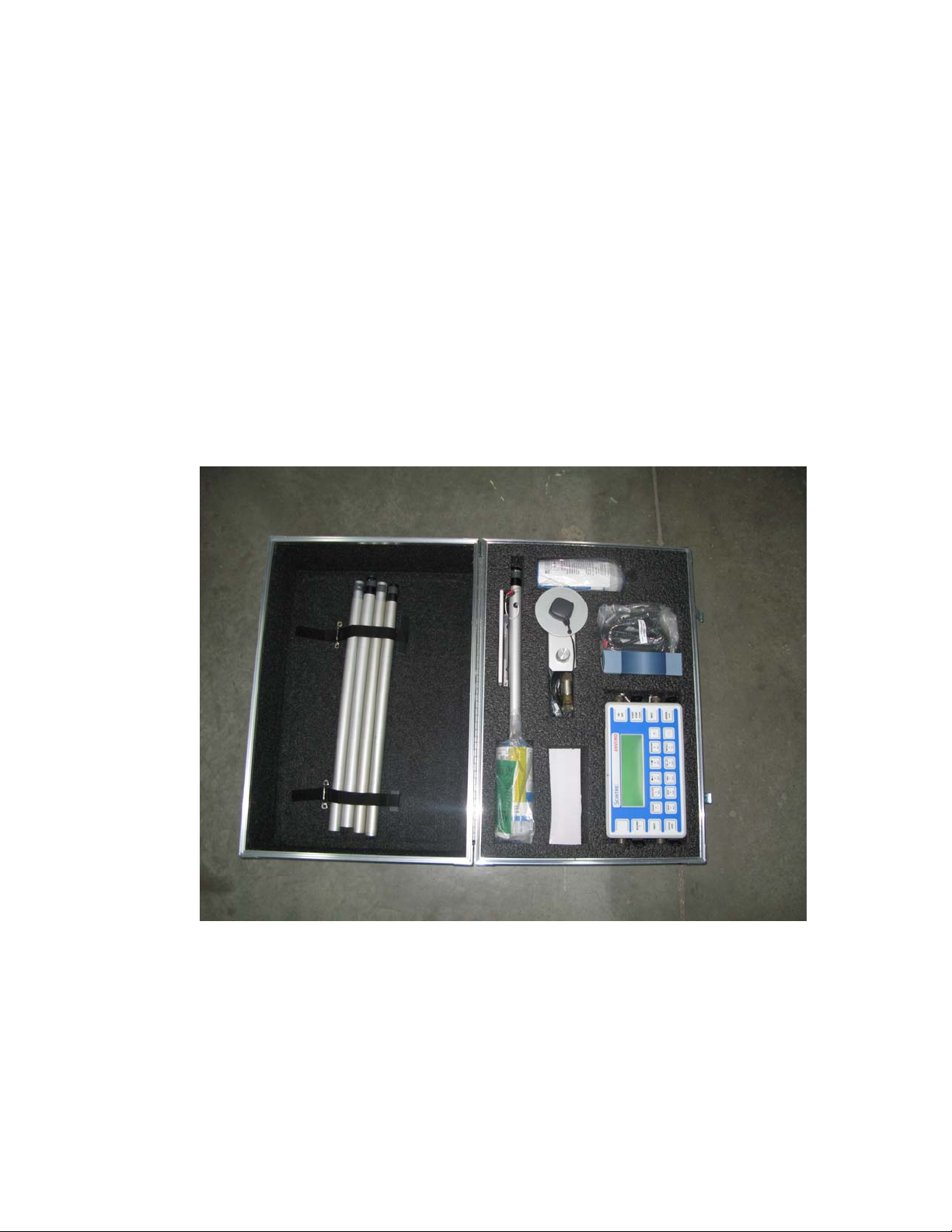
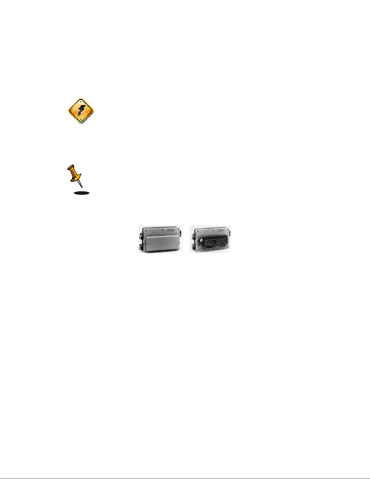
The following photographs show the basic components (less packing materials) of
the standard ENVI PRO.
3—1
The basic ENVI PRO kit
P/N 788715 Rev. 0
Unpacking
The standard ENVI PRO is shipped in a carrying/shipping case The ENVI PRO with
its accessories is packaged in cut-out sections in the case. This provides a proper
place for every item when you repack your instrument for shipping or storage. These
foam layers are disassembled in the following order, starting at the top:
Repacking
Warning: The batteries must be removed from the ENVI PRO
console prior to shipping or storage. Failure to do so
may result in damage.
Assembly
In order to make the system as compact as possible for shipment and
storage, and considering the various sensor configurations available, the
ENVI PRO requires you to connect up the external components. This
section will describe the steps required to completely assemble your
instrument.
Connecting the magnetic sensor(s) to the cable
The following illustrations show the proper cable connections for each of
the different magnetic sensor configurations. The sensors are shown being
viewed from their bottoms looking at the screw terminals.
Important: All parts near the sensor are non-magnetic. It is highly
recommended that you use only the brass screws and
wire connectors supplied by Scintrex. There are
additional screws for the terminals and cable hold-down
in the minor spare parts kit (Scintrex p/n 788030). If
you ever need to replace any of these parts under field
conditions please ensure that they are made of non magnetic materials.
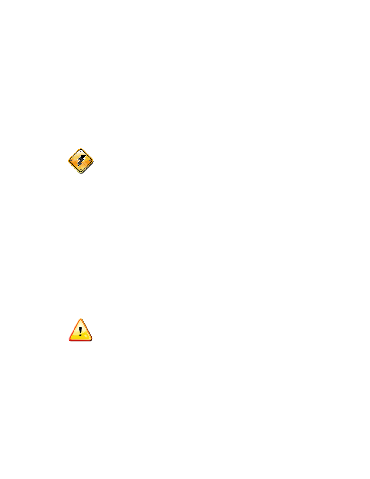
Total-field senso r
1. Orient the sensor so that as you look at the bottom of the sensor (the end with the
terminals), the large square plug is at the 9 o’clock position.
3—2
P/N 788715 Rev. 0
Preparing
2. Use either Scintrex cable number 780547 (the shorter one) for the backpack
configurations or cable number 780550 for the staff configuration.
3. Remove the cable hold-down plate by unscrewing the screws at the 2 o’clock and
4 o’clock positions.
4. Connect the black spade-lug on the bare wire of the cable to the terminal at the 11
o’clock position.
5. Connect the red spade-lug on the white wire of the cable to the terminal at the 11
o’clock position.
6. Place the cable in the smaller slot just below the 3 o’clock position.
7. Re-attach the cable hold down plate.
Total Field Sensor Cabling
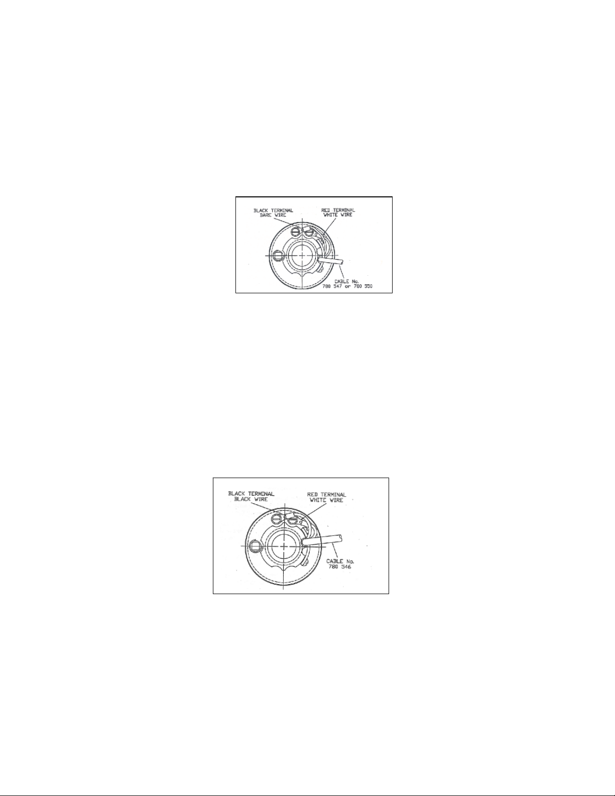
Base-station sensor
1. Orient the sensor so that as you look at the bottom of the sensor (the end with the
terminals), the large square plug is at the 9 o’clock position.
2. Use Scintrex cable number 780546.
3. Remove the cable hold-down plate by unscrewing the screws at the 2 o’clock and
4 o’clock positions.
4. Connect the black spade-lug on the black wire of the cable to the terminal at the
11 o’clock position.
5. Connect the red spade-lug on the white wire to the terminal at the 1 o’clock
position.
6. Place the cable in the larger slot just above the 3 o’clock position.
7. Re-attach the cable hold down plate.
Base-Station Sensor Cabling
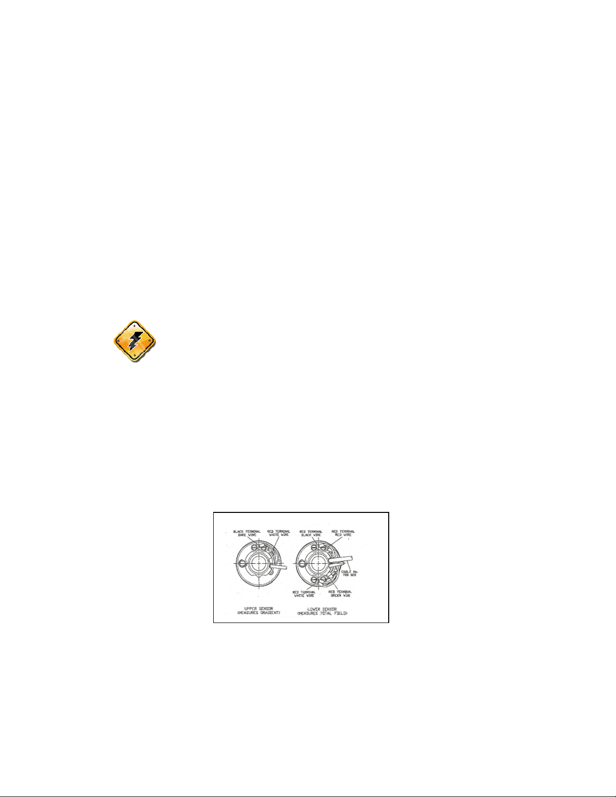
Gradiometer Sensors - Lower Sensor
1. Orient both the sensors so that as you look at the bottom of the sensors (the end
with the terminals), the large square plug is at the 9 o’clock position.
2. Use Scintrex cable number 788028 - it has four conductors.
3. Select the lower sensor - it has pairs of terminals at the 12 o’clock and 6 o’clock
positions, as well as an attached cable to the terminals at the 6 o’clock position. See
Gradiometer sensor cabling on page 3—4.
3—3
P/N 788715 Rev. 0
Preparing
4. Remove the cable hold-down plate by unscrewing the screws at the 2 o’clock and
4 o’clock positions.
5. Connect the red wire of the cable to the terminal at the 1 o’clock position.
6. Connect the black wire of the cable to the terminal at the 11 o’clock position.
7. Connect the green wire of the cable to the terminal at the 5 o’clock position.
Please ensure that the already attached bare wire of the smaller two-conductor cable
remains attached.
8. Connect the white wire of the cable to the terminal at the 7 o’clock position. Please
ensure that the already attached white wire of the smaller two-conductor cable
remains attached.
9. Place the smaller two-conductor cable into the smaller slot just below the 3 o’clock
position.
10. Place the larger four-conductor cable into the larger slot just above the 3 o’clock
position.
11. Re-attach the cable hold-down plate.
Gradiometer Sensors - Upper Sensor
12. Select the upper sensor - it only has a pair of terminals at the 12 o’clock position.
See Gradiometer sensor cabling on page 3—4.
13. Attach the upper sensor to the lower one by placing the shaft of the lower sensor
into the socket of the upper one while rotating slightly counter-clockwise. When they
are fully engaged, firmly twist them clockwise against each other.
Warning: Both sensors must have their directional marks aligned
in the same manner, i.e. the N on the top sensor must
be in-line with the N on the bottom sensor.
14. Remove the cable hold-down plate of the upper sensor by unscrewing the screws
at the 2 o’clock and 4 o’clock positions.
15. Connect the white wire of the two-conductor cable coming from the lower sensor
to the terminal at the 1 o’clock position.
16. Connect the black wire of the two-conductor cable coming from the lower sensor
to the terminal at the 11 o’clock position.
17. Re-attach the cable hold down plate.
Gradiometer sensor cabling
Installing the terminal protective cover
A plastic cup-like assembly is included to slide over the base of the sensor(s) to
protect the terminal connections from the elements.
3—4
P/N 788715 Rev. 0

Preparing
To install the cover:
1. Slide it over the sensor shaft with the widest end pointing towards the sensor.
2. Slide the supplied O-ring into the grove on the shaft to lock it into place.
To remove the cover, just reverse the above procedure. First remove the O-ring and
slide the cup away from the sensor.
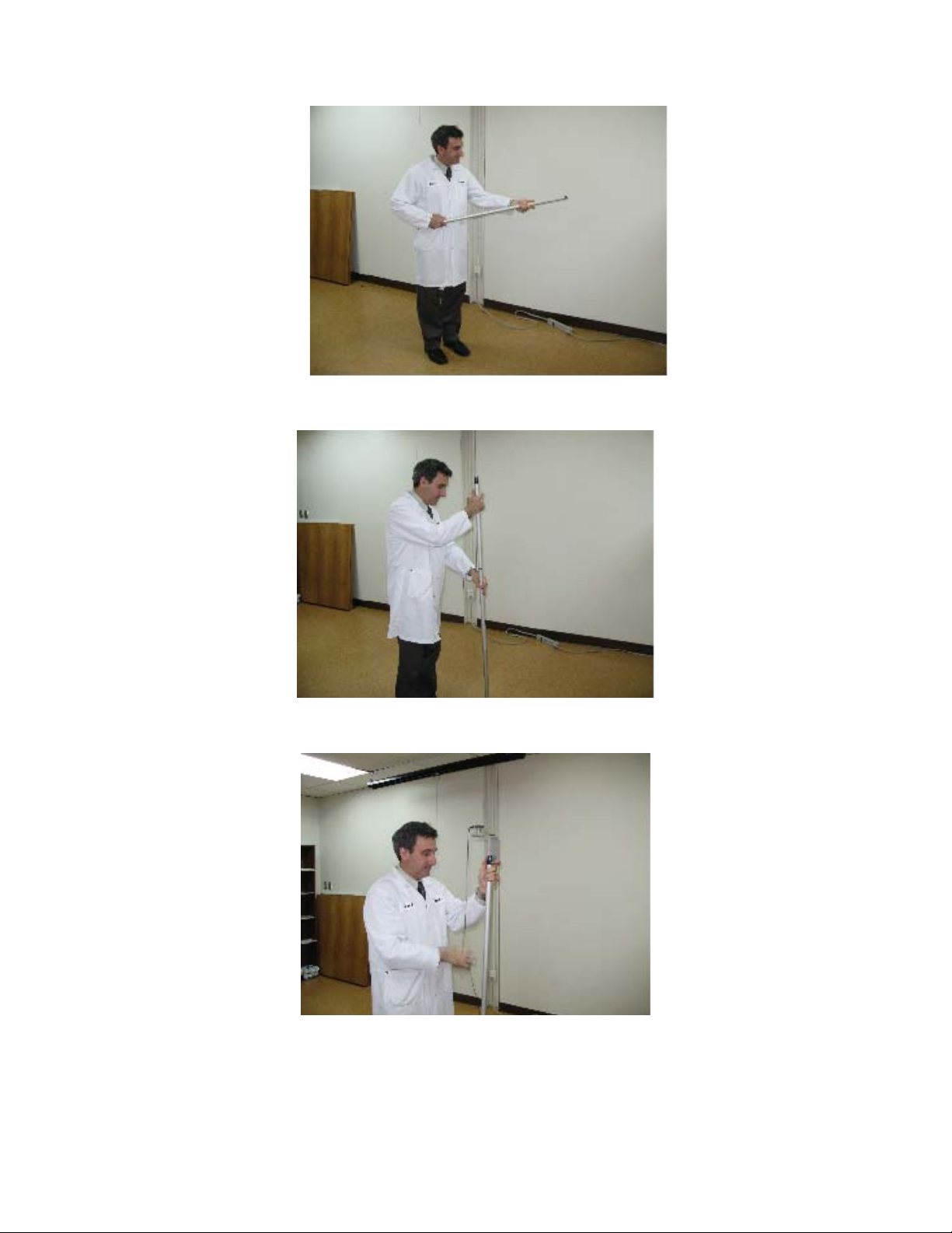
Assembling the sensor / GPS staff
Note: You can disregard this section if you are going to be using the
ENVI PRO in the backpack mode.
The sensor staff is shipped in four sections. These sections are located in the
shipping case slot labeled Sensor and Staff. You should note that one of the sections
has a sealed bottom, and you should start assembling the staff with this section.
Staff sections are assembled individually and connected to the sensors as follows:
1. Insert the male end partially into the female end and rotate counter-clockwise while
gently pushing the two parts together.
2. When they are fully engaged firmly twist them clockwise against each other.
Staff Mounted Installation
A staff mounted configuration is the most convenient when carrying out a
magnetometer survey in the stop-and-go mode.
The following steps are required to properly assemble the ENVI PRO sensor and
GPS antenna in the staff mounted configuration.
1. Assemble the staff sections as illustrated.
3—5
P/N 788715 Rev. 0
Preparing
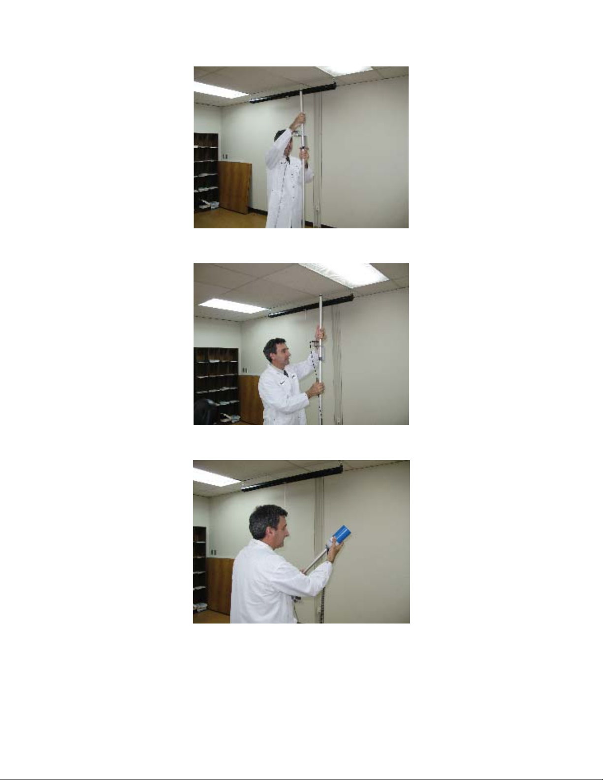
2. Insert the GPS antenna mount as illustrated.
3. Insert another staff section in order to clamp the GPS antenna mount between two
staff sections as illustrated.
3—6
P/N 788715 Rev. 0
Preparing
4. Insert the magnetometer sensor on the top section as illustrated.
3—7
P/N 788715 Rev. 0
Preparing
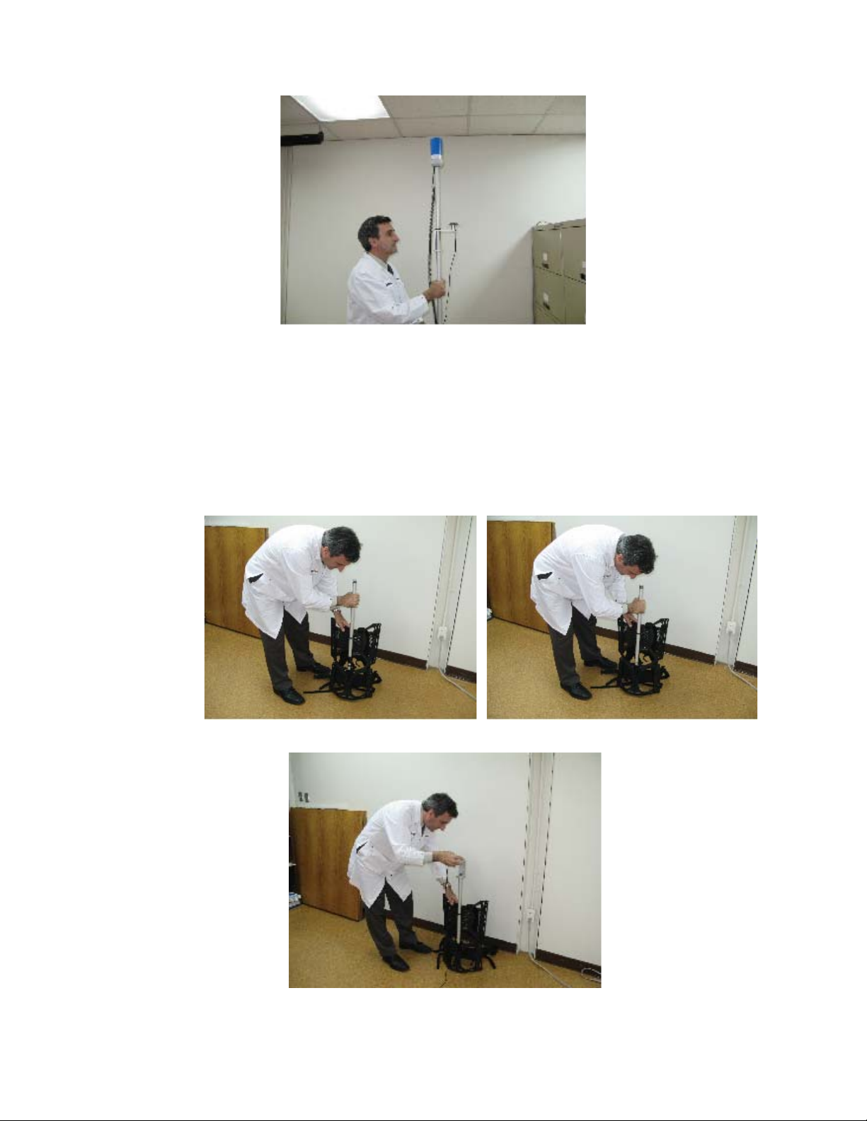
Back-pack Installation
A back-pack mounted configuration is the most convenient; providing a hands-free
operation for the ENVI PRO.
The following steps are required to properly assemble the ENVI PRO sensor and
GPS antenna in the back-pack configuration.
1. Insert a staff section in the staff mounting insert located on the back-pack as
illustrated.
2. If you are using the GPS antenna, insert the GPS antenna mount on top of
the previous staff section, as illustrated.
3. Insert a second staff section, as illustrated. The GPS antenna mount will thus
be lodged between two staff sections.
3—8
P/N 788715 Rev. 0

Preparing
4. Insert the magnetometer sensor at the top of the second staff section, as
illustrated.
3—9
P/N 788715 Rev. 0
Preparing
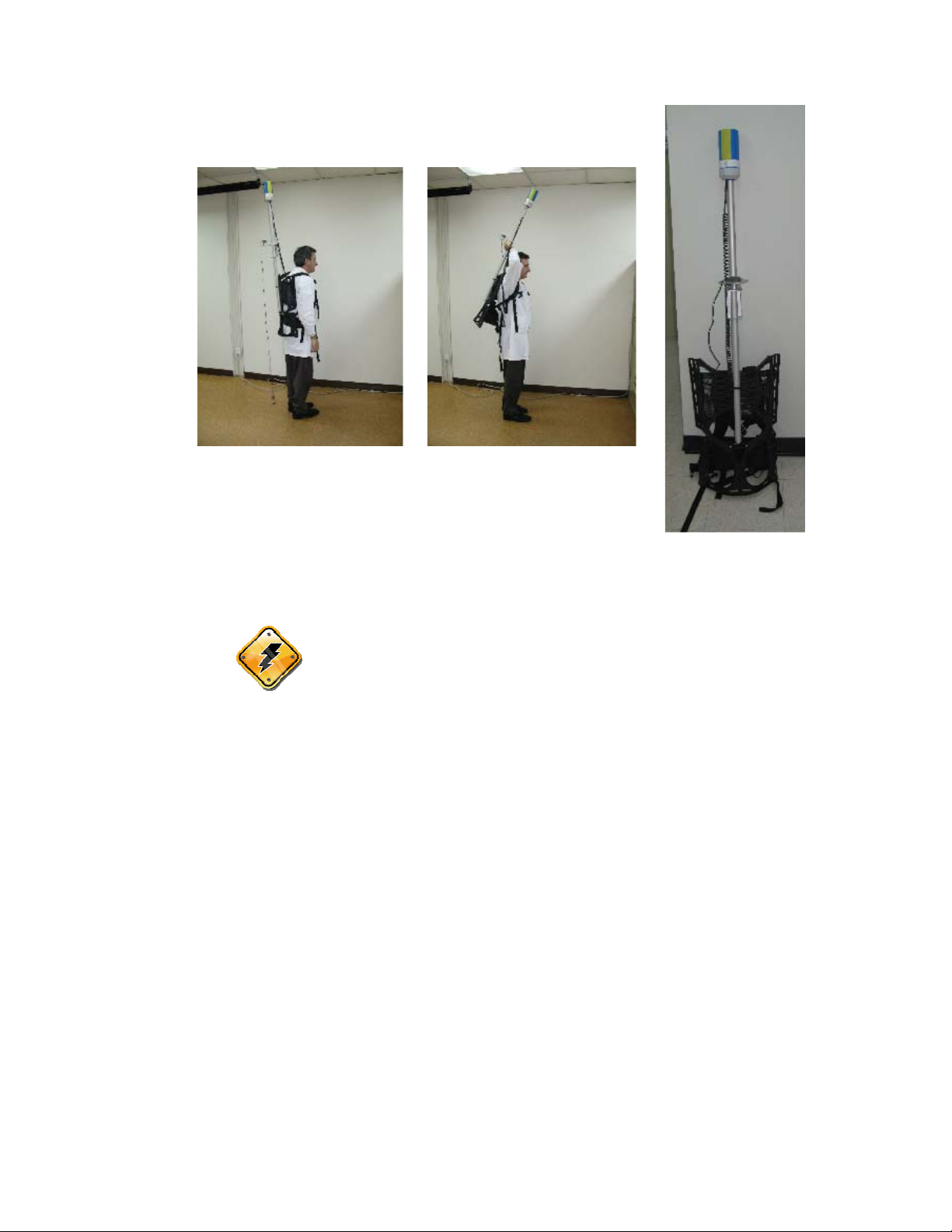
Complete Assembly
Warning: You need to consider your travel direction wile
surveying when you attach the sensor. The
magnetometer’s performance is a function of the
sensor’s orientation with respect to the earth’s
magnetic field. Therefore you must ensure that the N
mark on the sensor faces either magnetic north (or
south – either is allowed due to symmetry). Please
see Orientation on page 7-1.
Battery Installation/Exchange
The ENVI PRO is shipped without the battery installed. This is the proper procedure,
while shipping and storing the instrument, to prevent deep discharge of the battery.
Deep discharge can possibly cause permanent damage to the battery and will always
shorten the battery life. This situation will occur because a small current is being
drawn even if the instrument is turned off.
The following steps outline the battery installation:
1. Turn the instrument face down on a clean and even surface.
2. Unscrew both knurled screws on either side of the battery cover and lift the cover
off.
3. Place the battery into the recess in the rear panel of the instrument.
3—10
P/N 788715 Rev. 0
Preparing
4. Connect it carefully to the MAIN BATTERY connector. It is not important which
side of the plug is up, as long as the connector pins are properly aligned.
5. Replace the cover and tighten both knurled screws.
6. If this is the first time installation proceed with battery charging.
The small size and low cost of the battery makes it convenient to carry an additional
battery along as a spare.
Warning: An internal battery keeps the memory and the internal
clock alive for about 10 minutes. It is strongly advised
that the switching to the spare battery be done quickly,
to prevent the loss of your data.
Note: You need not worry about a low battery causing data loss,
since the memory power requirements are much less than
those needed to make a valid reading of the magnetic field.
ENVI PRO battery pack
Using the external battery pack
Cold weather use and extended WALKMAG surveys may require more power than
the standard battery together with a spare can provide. To satisfy this additional
requirement, the External Heavy Duty Battery Pack (Scintrex p/n 788026) is
available. It provides about three times as much power as the standard battery. This
battery pack can be carried by the strap or attached to a belt.
To connect the external battery you must proceed as follows:
1. Turn the instrument face down on a clean and even surface.
2. Unscrew both knurled screws on either side of the battery cover.
3. Lift off the cover and store it somewhere convenient for future use with the
standard battery configuration.
4. Remove the ENVI PRO STANDARD battery.
5. Connect the connector in the dummy battery cover carefully to the MAIN
BATTERY connector. It is not important which side of the plug is up as long as the
connector pins are properly aligned.
6. Place the new cover on to the console by gently pushing it into place and tighten
the knurled screws on the both sides.
3—11
P/N 788715 Rev. 0

Preparing
7. Please check the battery voltage condition at this stage and charge the battery, if
required.
External Heavy Duty Battery Connection
Using an external power supply
More demanding applications, such as an extended base-station operation, may
require more power than can be provided with either of the Scintrex supplied battery
packs. In this case you have two options:
a) AC Power
If a source of AC power is available, the instrument can be run while the charger is
connected to it. You will also be charging the standard internal battery, if it is
installed, at the same time.
Note: Please be aware of possible magnetic noise from generators,
and ensure that all cabling and sensors are as far away as
possible from the generator.
b) 12 volt battery (car or marine)
A 12 volt car battery may be more appropriate for other applications. The special
External Power Cable (Scintrex p/n 788029) should be used for this purpose.
1. The standard internal battery may be left in place.
2. Plug in the end of the cable with the single plug into the Charger Connector at the
right-rear side of the ENVI PRO console. See item 6 in the figure on page 4—2.
3. Connect the end with the clips to the battery terminals. The red cable-clip goes to
the positive battery terminal. The black cable-clip goes to the negative battery
terminal.
3—12
P/N 788715 Rev. 0

Preparing
Important: The correct polarity must be used for the instrument to
operate properly.
3—13
P/N 788715 Rev. 0
Chapter 4 The Instrument
This chapter is about the instrument itself and fully describes:
• The ENVI PRO console
• The keypad functions
• The various display menus
• The display formats that you will encounter
4—1
P/N 788715 Rev. 0

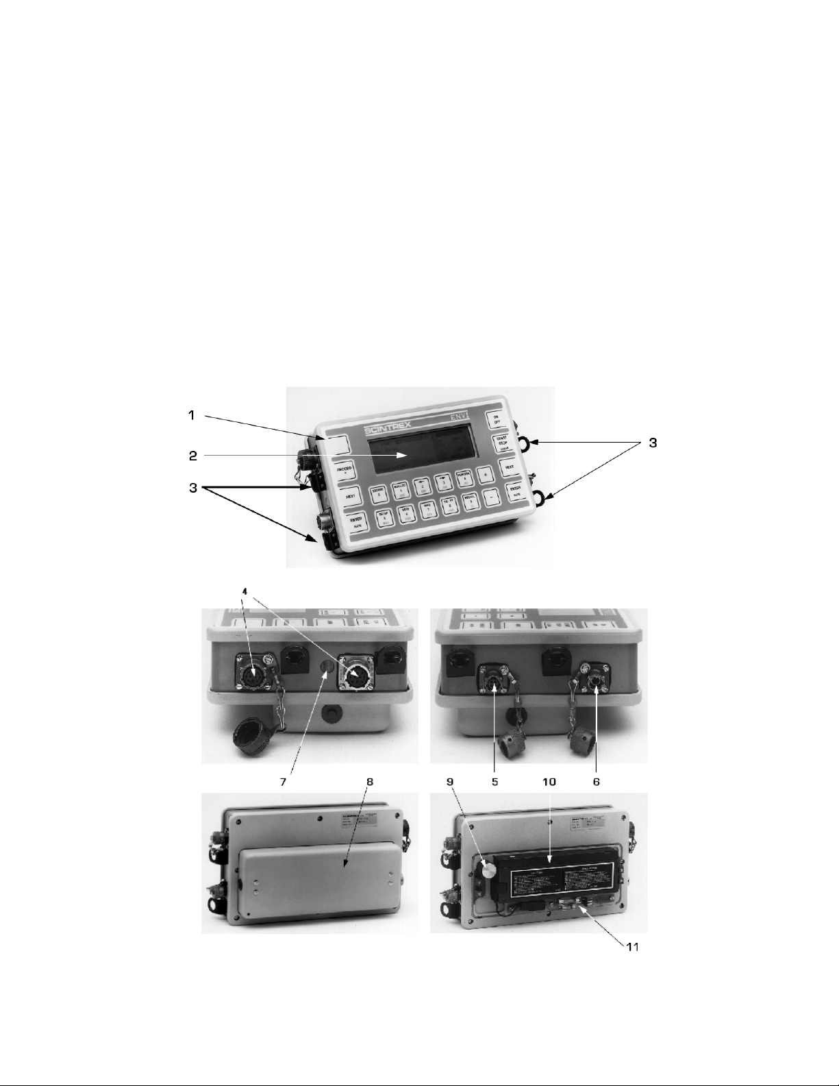
Console
Console Description
# Item Description
1 Keypad The fully sealed Keypad has 19 keys and a sound port.
Liquid Crystal
2
Display (LCD)
Carrying Strap
3
Attachment
4 Sensor Connector
Data Output
5.
Connector
Charger/External
6
Power Connector
The large 8 line by 40 character (64 x 240 dots)
Supertwist LCD (with a wide temperature range) presents
status and data in a numeric or graphic format.
Four rings at the side of the console that allow attachment
of the carrying harness.
Up to two sensor connectors may be present at the left
hand side of the console. The nearer one J102, 10 Pin
connector, is reserved for the magnetometer sensor.
The J101, 8 Pin connector is reserved for the GPS
antenna.
The data output connector carries RS-232 data dump
signals, as well as the analog signal for a strip chart
recorder and is located at the right hand side of the
console.
It has the following pin assignments:
A – common (ground) B – RS-232 receive data
C – RS-232 transmit data C – analog out 0-1 Volt
This connector accepts the charger to recharge either the
standard battery or the external heavy-duty battery pack.
It also accepts external, well filtered, 11 to 16 Volt DC
input.
The center pin is negative (-)
The shell is positive (+)
7 Charging Light
Battery
8
Compartment
9 Desiccant Cartridge
10 Battery
11 Fuse The standard 1.5A fuse to use with the standard battery.
The charging light (visible through a window on the left
side) indicates that the battery is charging at a high rate.
The battery compartment is located at the back of the
console and contains one rechargeable lead-acid battery,
the desiccant cartridge and the fuse. The battery cover is
replaced with another cover with a cable attached when
the external battery is used.
The desiccant cartridge is a cylindrical re-usable capsule
filled with a drying agent. It absorbs any moisture that
my get inside the instrument.
A rechargeable lead-acid battery in the standard ENVI –
MAG configuration.
Keypad Description
4—2
P/N 788715 Rev. 0
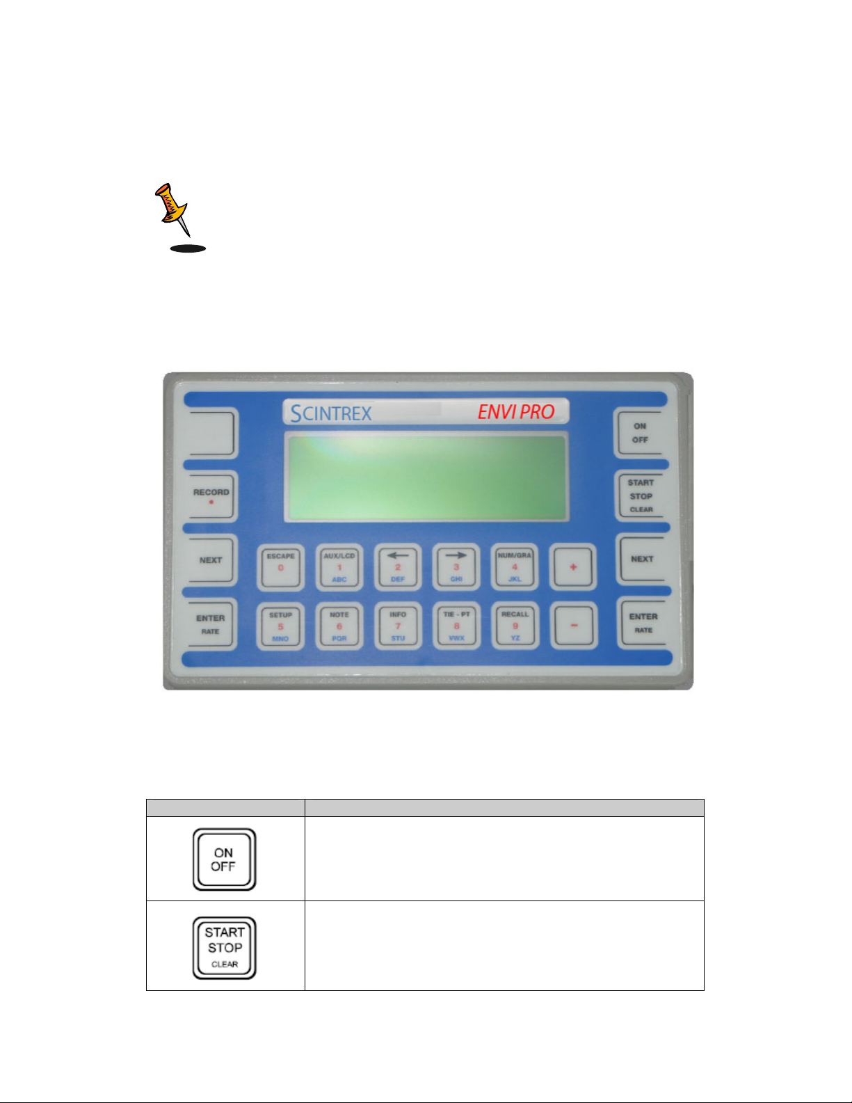
Console
The keypad has 19 keys. Two of the most used keys are duplicated on the right and
left sides of the console for easy access. Some keys have up to three separate
functions assigned to them. The response of these multifunctional keys depends
upon the operation in progress.
Note: The function mode of the keys has precedence over the alpha-
numeric mode of the keys.
Key Functions
Key Description
4—3
The ENVI PRO keypad
Turns the instrument on and off. Turning the instrument off
during a reading abruptly terminates a reading with the loss
of the current data.
Starts or stops an operation, such as data acquisition, data
dumping, data recall, etc.
*When the instrument is in the Notes operation, this button
acts as a “backspace” key to delete entries.
P/N 788715 Rev. 0
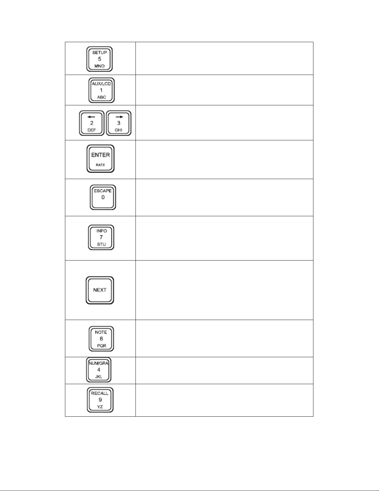
Console
*Accesses the various setup displays. The actual setup
menu that will be displayed depends upon the display
screen in which this key is pressed.
*Accesses the Auxiliary Functions display allowing:
- setting of the LCD intensity
- data output
- locking of the setup parameters
Moves the cursor to the left or up; to the right or down.
2 identical keys:
- opens and closes the parameter fields during setups
- opens and closes the scaling option field for the graphics
display
- toggles the sample rate in the walking type survey.
Allows escape from a deeper level in a program to a higher
level, ultimately to the top level, which is signified by the
Main operating display.
Aborts a data dump.
*Accesses the Info. Display, which allows:
- setting of data and time
- enabling and selecting GPS coordinates
- entering of serial and job numbers, and operator
identification
- observation of memory availability.
2 identical keys:
- scrolls sequentially through numeric data display pages
- scrolls sequentially through graphic data display pages
- moves the cursor from one sub-page to the next sub-page
- moves the cursor to the next character location during note
entry
- advances the station number by station separation in the
walking mode.
*Accesses the Note Entry display, which allows:
- the entry of five common notes (macros) to be recorded
repeatedly with selected readings
- the entry of unique notes to be recorded with a particular
reading.
4—4
Toggles the data display between numerical and graphic
data presentation during data acquisition only.
*Presents the Recall display for selection of:
- data item to be recalled
- setting of the starting location or time of the recall.
P/N 788715 Rev. 0
Console
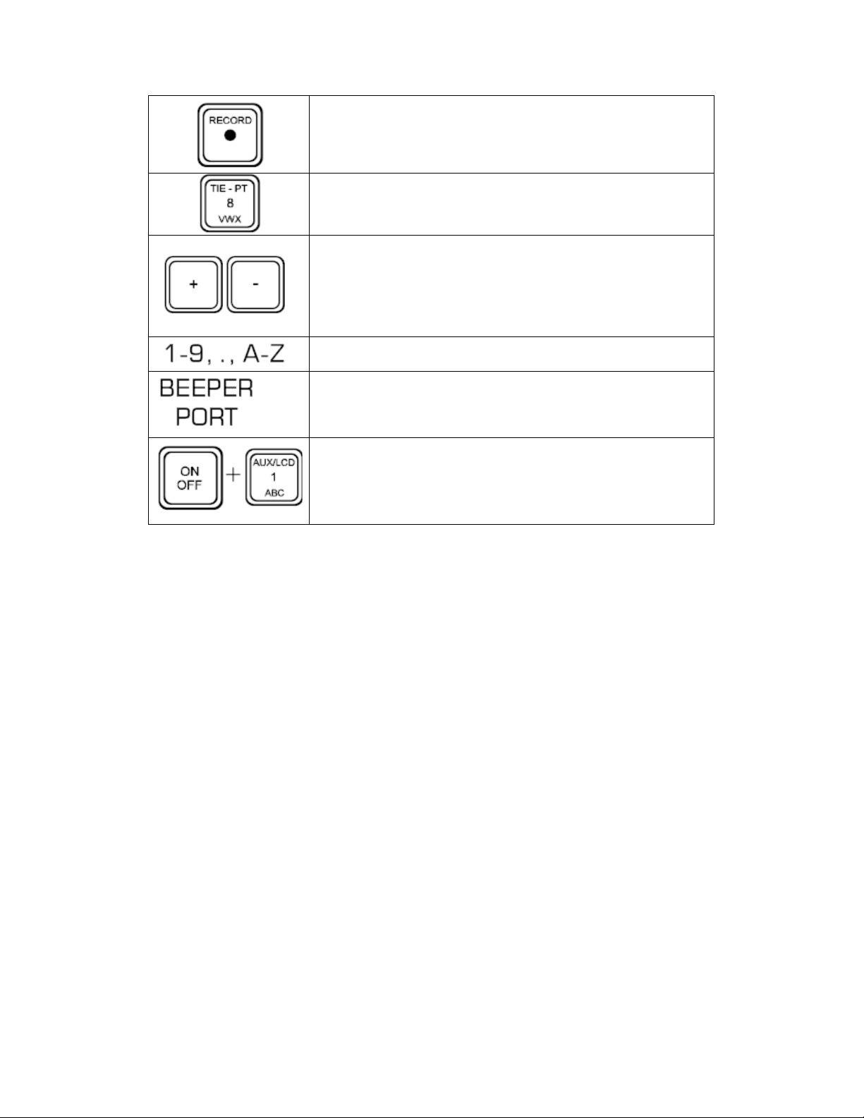
*Manually records measured data and notes in internal
memory.
Acts as the START key at a Tie-point. This is used for the
Tie-point line and loop mode corrections.
Facilitates the scrolling forward or backward through a list of
items:
- allows sign entry to numbers
- allows panning along a line of data during recall
- increments or decrements the line and station number in
the Stop-and-Go mode.
*Allows alpha-numeric entry for setups and notes.
This blank “key” in the upper left corner of the console is not
actually a key, but a flexible membrane to enhance the
* These items/key functions are only operational when you select the advanced
operating modes (options 5 to 7) from the initial configuration menu.
loudness of the beeper.
Pressing the “ON” and “AUX/LCD” keys simultaneously
performs the COLD BOOT operation, resetting the
instrument to factory defaults.
Display Screens
The ENVI PRO currently has the following types of displays:
• Help screens
• Confirmation screens
• Parameter selections screens
• Note entry screens
• Numeric data displays
• Graphical data displays
• Pop-up options and confirmations
General Information
Most of the screens consist of three bands of information as shown below:
4—5
P/N 788715 Rev. 0
Console
General display information bands
The Title Line at the top indicates the current operating functions.
The middle six lines contain specific display information consisting of either
instrument and survey parameters or data.
1. The bottom line usually contains prompts for actions, such as pressing the
key required to start an operation. Miscellaneous messages may also appear
here. The battery voltage (values between 100 and 140) is also shown on the
right-side of this line.
Note: The instrument automatically turns off (blank display) to
conserve battery power, if there is no reading or key stroke
detected for 30 minutes.
Cursor
A large, blinking cursor indicates the specific parameter that
can be altered to change setups, starting station value, station or line spacing, and so
on. The cursor is moved from parameter to parameter or line to line by pressing the
arrow keys to move in the desired direction. The prompt on the bottom line will let
you know which key to press to make any changes.
Display Blocks
Some displays are divided into two or more blocks or sub-panels. The blocks are
separated by solid partition lines as shown in the following figure.
4—6
P/N 788715 Rev. 0

Console
Instrument display showing information blocks (sub-panels)
To move the cursor from one block to another, press the “NEXT” key.
Some measured data is displayed on more than one page (display screen).
Switching between pages is also done by pressing the “NEXT” key. The display
screens are designed so that these multi-page displays do not have separate subblocks. All of this is discussed in detail under “Advanced mode data displays” on
page 5—8.
Pop-Up Windows
Some displays will have pop-up windows (either on the right or left side of the main
display) that will contain:
• Prompts for selecting or changing parameters
• Confirmations and warnings of impending operations requiring a Y(yes) or N
(no) entry from the keypad
• Status indication of an operation under way, such as data output
• Synchronization of the Real Time Clock of the ENVI PRO console with the
GPS time signal
Sample pop-up windows
Help Screens
4—7
P/N 788715 Rev. 0

Console
On line help is also available. There are three screens of information providing a
quick reference on how to do most operations and which buttons to push. The
screens are as follows:
4—8
Help screens available
The help screens are displayed when you press the
“INFO” button. Whenever you see the text “help: INFO” in
the bottom prompt line of a display, you can activate the
help screens.
To toggle to another help screen, press the “+” or “–“ key.
The screens change in a cyclical manner.
To return to the MAIN OPERATING menu, press the
“ESC” key.
P/N 788715 Rev. 0

Operating Displays
4—0
P/N 788715 Rev. 0

Operating Displays
Chapter 5 Operating Displays
The various display screens with and without GPS will be discussed in this chapter.
Main Operating display
MAIN OPERATING display with and without GPS appears as follows:
Main operating display without GPS
Main operating display with GPS in Lat/Lon coordinate
5—1
Main operating display with GPS in UTM coordinate
P/N 788715 Rev. 0

Operating Displays
The configurable parameters of the MAIN OPERATING display are:
Parameter Description
MAG
ST
SEP
DIVBY
LN
LON
LAT
EASTING
mmm shows which type of magnetometer measurement is
currently enabled, and therefore ready to be started.
The station number for this measurement.
It consists of the numeric part (ssss.s) and the directional part (d).
The range is from 0 to 99999 with a decimal point as required.
The direction allows the entry of the geographical direction or the
Cartesian co-ordinates. The allowed entries are N,E,S,W, + or -.
The line or station separation.
The range is from 0 to 99999 with a decimal point, as required,
and can either be positive (+) or negative (-). It may not
necessarily represent the reading separation.
See the “NEXT” key and AUTO. St. INC. for more information.
When the separation is positive, the station number gets
incremented by the separation.
When the separation is negative, the station number gets
decremented by the separation.
NOTE: a negative (W,S,-) station, when incremented, becomes
less negative, and vice versa.
Trigger switch closure counter.
The line number, along which the measurements take place.
It consists of the numeric part (1111.1) and the directional part (d).
The range is from 0 to 99999 with a decimal point as required.
The direction allows you to enter the geographical direction or the
Cartesian co-ordinates as one of: N,E,S,W, + or -.
The GPS longitude of this measurement in lat_lon coordinate.
It consists of the positive numeric part (ll.llllll) and the directional
part (W or E).
The GPS latitude of this measurement in lat_lon coordinate.
It consists of the positive numeric part (ll.llllll) and the directional
part (N or S).
The GPS easting of this measurement in UTM coordinate.
It consists of the positive numeric part (eeeeeee.e).
5—2
P/N 788715 Rev. 0

Operating Displays
The GPS easting of this measurement in UTM coordinate.
NORTHING
It consists of the positive numeric part (nnnnnnn.n).
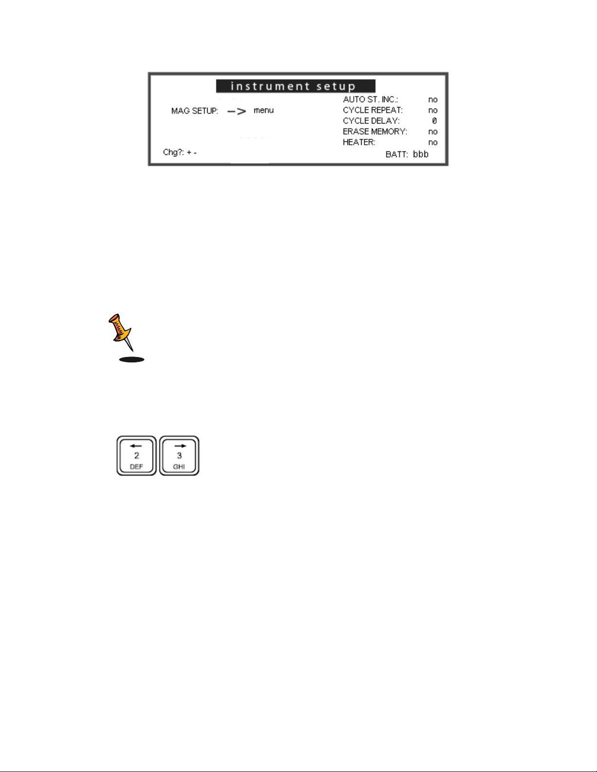
Instrument setup display
This display enables you to configure the basic data acquisition
portion of the ENVI PRO and is accessible with the “SETUP” key.
ENVI PRO instrument setup display
Parameter Description Default
Displays the magnetometer specific
MAG
SETUP
AUTO
ST. INC.
CYCLE
REPEAT
setup menu.
Pressing the “ENTER” key gets the
next menu.
A “yes/no” toggle that controls the
automatic station increment
(decrement).
no - for the base station, walking or
manual type of operation.
yes – for semi-automatic operation.
Determines whether the
magnetometer will take one reading
only, or will continuously take
readings at the time interval specified
by the DURATION parameter I the
Mag. Setup.
This is not applicable for Base
Station operation, which is set in the
Mag Setup.
No
No
5—3
P/N 788715 Rev. 0

Operating Displays
The delay between readings when
the cycle repeat feature is enabled.
CYCLE
DELAY
ERASE
MEMORY
HEATER
It affects the total-field magnetometer
or gradiometer only.
The base-station repetition rate is
controlled in the Mag. Setup under
Cycle Time.
Allows clearing of the data memory.
A request for confirmation will be
displayed before the actual erasure
takes place.
NOTE: The setup parameters remain
intact.
Enables or disables the LCD display
heater.
If the temperature is above – 15° C,
enabling this parameter has no
effect.
0
No
No
Magnetometer setup display
This display is different depending on if GPS is enabled or
not.
This display provides access to the parameters affecting
the operation of the magnetometer portion of the ENVI.
This display is accessible from either the Instrument setup display, or
from the Main operating display (by using the short-cut, i.e. pressing
the “ENTER” key).
5—4
P/N 788715 Rev. 0

Operating Displays
Magnetometer setup display with GPS disabled
Magnetometer setup display with GPS enabled
Parameter Description Default
Allows the selection of:
- Total Field
Magnetometer
MODE:
DURATION
(default)
- Gradiometer
- Base Station
- Off (will disable the
ENVI PRO)
The measurement duration.
A choice of 0.5, 1 or 2 seconds is
available.
The correct selection depends on the
desired measurement accuracy and
the spacing of the stations when
using the WALKMAG mode of
operation.
The duration also controls the
repetition rate if CYCLE REPEAT
with a CYCLE DELAY of 0 (zero) was
chosen in the ENVI instrument setup.
The longest duration results in the
highest precision.
Tfld
0.5
5—5
P/N 788715 Rev. 0

Operating Displays
The value of the Earth’s ambient
magnetic field in the survey area.
For best performance, the tuning field
should match the ambient field as
closely as possible, at least to within
+/- 1000 nT.
TUNE
FIELD
BASE
CORRECT
TIE
CORRECT
CYCLE
TIME
A map showing the approximate field
intensity on the Earth’s surface can
be found in Section B: Applications.
The values shown can be used as a
starting point, and applied equally to
the Total-field sensor or the
Gradiometer sensor.
See also AUTO TUNE.
A “yes/no” toggle that applies a
BASE-STATION correction using
data supplied from a base-station
ENVI PRO.
You must press the “+” key to toggle
the YES on.
You need to have the base-station
connected as described in “Using
base-station data”.
A request for confirmation will be
displayed in a pop-up window before
your data is corrected. You must
press the “9/YZ” (Yes) key to begin or
the “5/MNO” (No) key to abort.
NOTE: The original raw data is
changed.
A “yes/no” toggle that applies a tiepoint correction using data collected
in the TIE mode.
Selecting this opens a window
indicating which tie-point (loop or
line) correction mode is in effect. You
must enter “Y” to start the correction.
NOTE: The original raw data is
changed.
The reading interval of the base
station.
The allowable range is 0 to 99999
seconds.
0
No
No
0
5—6
P/N 788715 Rev. 0

Operating Displays
Entering 0 (zero) results in a reading
interval equal to the reading time.
The instrument goes to “sleep”
between readings, for 4 seconds and
up.
The sensitivity for the analog output
CHART
SCALE
AUTO
TUNE
BASEFIELD
for the strip chart recorder.
The following choices are available:
1, 10, 100, 1000, 10000 nT.
A “yes/no” toggle that controls the
automatic tuning function.
It is independent for the Total-field
sensor and the Gradiometer sensor.
The tuning value is updated after
each reading in preparation for the
next one.
Auto tuning is particularly applicable
if large variations of the ambient field
are encountered over longer
distances.
Fixed tuning may be more
appropriate in areas of large cultural
electrical noise or very narrow, large
amplitude anomalies. These may
pull the tuning away from the desired
frequency to that of the interfering
frequency or to tuning field values
greatly different from the background.
As the setting of this parameter
depends upon your particular survey
conditions, it is not possible to
suggest the best setting. The mode
should therefore be established by
experimenting. In general it is more
applicable to use fixed tuning for the
site characterization and drum
location modes.
The base field is used in conjunction
with the base-station correction
procedure.
The base-station correction
technique removes variation in the
ambient field during the time that the
base station is running. However,
variations taking place from day to
day are not corrected. The base field
1
No
0
5—7
P/N 788715 Rev. 0

Operating Displays
value is used for this purpose.
The actual value is not critical, as
long as it is the same for all
instruments in the survey. It is
important that this value not be
changed during the entire survey. A
logical value is the first reading of the
base-station on the first survey day.
Allows you to select either the Line or
Loop type of tie-line correction.
TIE MODE
AUTO
RECORD
NOTE: The Tie-line correction
method is substantially less precise
than the base-station correction
method.
A “yes/no” toggle.
This function is used in the semiautomatic mode to save you from
having to press another key.
Auto Record is always in effect in the
base-station operation or if the Cycle
Repeat function is selected in the
ENVI PRO Instrument Setup.
Line
No
Data Displays
Data is displayed on a page by page basis in either numeric or
graphic form. There are up to two pages each. The “NUM/GRA”
key toggles between the two display forms. This display is different
depending on if GPS is enabled or not.
Numeric data display
Numeric displays are only available when the instrument is recording data, i.e. you
cannot “recall” the data in a tabular format as shown in the figure below.
The displays shown in the examples that follow are Pages 1 and 2 of the numeric
data display for the gradiometer. The difference between the two display pages is
that Page 2 shows the signal precession as a bar graph. This allows you to monitor
the quality of each reading.
The total-field and the base-station displays differ in that the gradient column is
absent.
5—8
P/N 788715 Rev. 0

Operating Displays
The following table shows the availability of a numeric display after pressing the
“NEXT” key.
* You will have to use the “RECALL” function, if you have pushed the
“ESCAPE” key.
Page 1 of the numeric data display with GPS disabled
5—9
Page 2 of the numeric data display with GPS disabled – signal strength
P/N 788715 Rev. 0

Operating Displays
Page 1 of the numeric data display with GPS enabled
in lat_lon coordinate
Page 2 of the numeric data display with GPS enabled
in lat_lon coordinate – signal strength
Page 1 of the numeric data display with GPS enabled
in UTM coordinate
Page 2 of the numeric data display with GPS enabled
in UTM coordinate – signal strength
Display Item Description
The magnitude measured by the lower total-field sensor in
nanoTeslas (nT).
TOTAL
5—10
The most current reading is the top most followed by preceding
readings.
P/N 788715 Rev. 0

Operating Displays
NOISE
GRADIENT
TIME
LN
ST
LON
LAT
EASTING
NORTHING
A number indicating the quality of the reading.
It is based on the noisiness of the individual periods of the
precession signal. The smaller the value the better the quality of
the reading.
The magnetic gradient between the two sensors.
Expressed in nT/m.
The current time in hours: minutes:seconds.
It is used to time stamp each reading.
The line number on which this measurement took place.
The value consists of the numeric and directional parts.
The station number to which the respective magnetic data applies.
The value consists of the numeric and directional parts.
GPS longitude in lat-lon coordinate on which this measurement
took place.
The value consists of the numeric and directional parts
GPS latitude in lat-lon coordinate on which this measurement took
place.
The value consists of the numeric and directional parts.
GPS easting in UTM coordinate on which this measurement took
place.
The value consists of the numeric only.
GPS northing in UTM coordinate on which this measurement took
place.
The value consists of the numeric only.
Graphic data display
The display shown below is page two of the graphic data for the gradiometer. Page
one appears identical, except that the word ‘GRADIENT” is changed to “TOTAL” and
a plot of the total field is shown. This display is different depending on if the GPS is
enabled or not.
The following table shows the availability of graphic displays after pressing the
“NEXT” keys.
5—11
P/N 788715 Rev. 0

Operating Displays
* You will have to use the “RECALL” function, if you have pushed the
“ESCAPE” key.
** Depends upon the status before “STOP” was pressed.
Graphic data display of Page 2 – without GPS
5—12
Graphic data display of Page 2 – GPS Lat/Lon
Graphic data display of Page 2 – GPS UTM
P/N 788715 Rev. 0

Operating Displays
Display Item Description
The display title indicating the data shown by the graph.
GRADIENT
LN
ST
LON
LAT
EASTING
NORTHING
The numeric value indicated by ggg.g is the respective gradient, at
the indicated Line and Station number
The line number along which this measurement took place,
consisting of the numeric and directional parts.
The station number, at the cursor position, to which the respective
magnetic data applies (consisting of the numeric and directional
parts).
GPS longitude in lat-lon coordinate on which this measurement
took place.
The value consists of the numeric and directional parts
GPS latitude in lat-lon coordinate on which this measurement took
place.
The value consists of the numeric and directional parts.
GPS easting in UTM coordinate on which this measurement took
place.
The value consists of the numeric only.
GPS northing in UTM coordinate on which this measurement took
place.
The value consists of the numeric only.
Recall Displays
The “RECALL” function is useful to view the collected and stored data. But the
RECALL function is disabled when GPS enabled.
Recall Setup display
This display allows you to select the type, location or time and date
of the data when GPS is disabled. This display is accessed by
pressing the “RECALL” key.
The RECALL SETUP display with GPS disabled
5—13
P/N 788715 Rev. 0

Operating Displays
The RECALL SETUP display with GPS enabled
Display Item Description
MAG
LN
ST
TM
DT
Warning: GPS must be disabled in order to recall t-fld and grad. data.
The station number is the starting location for the recall, consisting
This parameter is only present when the Base Station is selected.
This parameter is only present when the Base Station is selected.
Either one of Total Field, Gradient or Base Station.
The line number whose data is to be recalled, consisting of the
Not only the Time and Date, but the Line and Station numbers
must also be correct to successfully recall Base Station data.
The mode of the data collected.
numeric and directional parts.
of the numeric and directional parts.
The starting time of the recall.
The data of the data to be recalled.
RECALL DATA display
Note: Only Data collected and saved with GPS disabled can
5—14
be recalled, but only in graphic form and with GPS
disabled. Up to 178 readings can be shown at one
time. The display window can be moved sideways
(called panning) in steps of one half of its width (i.e. up
to 89 readings) to view adjacent data with the aid of the
P/N 788715 Rev. 0

Operating Displays
“+” or “-“keys. It is also possible to adjust the vertical
scale and bring any point to the vertical center of the
window.
Exact values can be read off the numerical section at the left hand side of the
display.
The Total Field display is shown and explained. The Gradient display differs in title
only. The Base Station display shows Time and Date instead of Line and Station.
Note that there are two pages of data for the gradiometer.
These displays are accessible with the “START” key when in the
RECALL SETUP display.
The RECALL DATA display
Display Item Description
The title of the display indicating the data shown by the graph.
TOTAL
LN
ST
The numeric value indicated by MMMMM.M is the respective totalfield value, at the indicated line and station number.
The line number along which this measurement took place,
consisting of the numeric and directional parts.
The station number to which the respective magnetic data applies,
consisting of the numeric and directional parts, at the cursor
position.
Modifying the display window
The graph can be altered by changing the vertical scale or by centering any point
vertically in the window. A smaller window can be opened up using the “ENTER”
key to allow changes. The changes take effect after you press “ENTER”.
5—15
P/N 788715 Rev. 0

Operating Displays
The RECALL Display ready for customizing
Display Item Description
Shown after the “ENTER” key is pressed.
SCL
It indicates the vertical full scale.
Scrolling using the +/- keys allows the full scale values of 1, 10,
100, 1000, 10000 nT.
This is the cursor, which is normally at the left edge of the window.
It can be moved with the aid of the ← and → cursor keys.
Numerical data at the left hand side of the display represents the
data at the cursor position.
Pressing the “0” key adjusts the display such that the point at the
cursor position becomes the center value of the graph.
Auxiliary Functions display
The Auxiliary Functions display is accessible by pressing the
“AUX/LCD” key. It provides additional functions which are not
directly accessible from the keyboard. You will need to press the
appropriate key to get to the function.
5—16
P/N 788715 Rev. 0

Operating Displays
The auxiliary functions display
Key Pressed
These keys allow you to adjust the intensity of the
LCD screen for better viewing under a variety of
lighting conditions.
This option allows you to access the Data Output
menu to transfer information to you computer or
printer.
This function is reserved for production and service
tests. It has no functions for you to use.
The lock option allows you to lock the ENVI PRO
setup parameters so that they are not accidentally
changed. To make any changes, you will have to
toggle this option first.
Action under
Auxiliary functions
Data Output Display
This display allows the selection of:
• Communication parameters between the ENVI console and the output device
such as a computer or printer.
• The data format of the output
• And possibly the Line number, if a line by line data dump is desired.
Data can be dumped in its entirety at once, or selectively on a mode basis.
This display is accessible from the AUXILIARY FUNCTIONS display. Depending on if
GPS is enabled or not, the display is different.
The data output display with GPS disabled
5—17
P/N 788715 Rev. 0

Operating Displays
The data output display with GPS enabled
Parameter Description Default
With the cursor placed after the
: all data
recorded
MAG
BY LN
LN
BAUD
DL
colon, all the data in the instrument
would be dumped sequentially into
one, possibly very large, file.
Lists the modes available for the
ENV-MAG. As shown, only the
gradiometer data would be dumped
as indicated by the cursor position.
yes/no
Directs the instrument to dump the
data on a line by line basis, in
addition to a method by method
basis.
This is usually left at no.
The line number whose data has to
be dumped, consisting of the numeric
and directional parts.
The Baud rate of communication with
the output device.
The following choices are available
by scrolling: 600, 1200, 2400, 4800,
9600, 19200, 38400, 57600 Baud.
A delay which may be added after
each carriage return/linefeed (CR/LF)
to accommodate slow peripherals
such as some printers.
The range is 0 to 999 ms.
This value is normally left at 0 for
dump to computers.
The proper setting has to be
established experimentally for other
equipment. Problems usually are
indicated by the loss of a few
characters.
No
9600
0
5—18
P/N 788715 Rev. 0

Operating Displays
The number of data bits.
The default value is 8 bits, which
usually works properly.
BIT
FMT
The proper setting has to be
established experimentally. For
example, on some printers, 7 or 8 bits
results in either normal or italic print.
The output data format.
8
Data output formats
The following table shows the available output formats for dumping the data to a
computer or printer.
Data output
format
XYZ
XYZ+
XYZ++
PRN
NOTES
XYZ is the simplest format.
It contains no heading or comments.
The individual data items are separated by a single space
character.
X and Y represent the Cartesian coordinates (N and E are positive
while S and W are negative).
Z is one or more items of magnetic data.
There is one set of data per printed line, including the time of the
measurement.
CAUTION: Due to the lack of header information, you should label
the files clearly.
XYZ+ is identical to XYZ but a header and user entered NOTES
are added.
XYZ++ is identical to XYZ+ but the data is now placed into
columns.
PRN is a format used with software for the Scintrex MP-3/4
Magnetometer.
NOTES outputs a report of all user entered NOTES, crossreferenced with the Line and Station number, or GPS coordinate
value.
Description
NOTES display
The notes display is useful for the entry of comments, which are stored with the data
at the particular Line and Station number.
5—19
P/N 788715 Rev. 0

Operating Displays
Macros (pre-recorded messages) provide a quick entry for repetitive notes which can
be entered while measuring. This display is accessible with the “NOTE” key.
The NOTES display
Parameter Description
Alpha-numeric characters, including “+”, “.” and “-“ up to 32
characters.
NOTES
MACROS
1:
…
5:
A note can be saved as one of five macros in a separate memory
for re-use.
MACROS are pre-recorded messages of up to 15 characters.
These are used to speed up note entry.
It is most advantageous to enter frequently encountered items,
such as road, fence, and so on.
Information / GPS Setup Display
This display screen is used for the entry of ancillary information and
GPS setup. You can also see how much free memory is available.
This screen is accessed from the main display by pressing the “INFO”
key. Fig. 1 shows the default display or with GPS disabled. In order to
enable or disable GPS, move the cursor to GPS and press “+” or “-“, a pop-up
window comes out as shown in Fig. 2. By selecting 2 or 3 to enable GPS and
configure it to either Lat/Lon or UTM coordinate. At this point, the real time clock
(RTM) is synchronizing with GPS time, as shown in Fig. 3. Fig. 4 and 5 show the
INFO screen with GPS lat/lon and UTM coordinate, respectively.
5—20
P/N 788715 Rev. 0

Operating Displays
Fig. 1 The default INFO display
Fig. 2 GPS setup display
Fig. 3 RTC synchronizing display
5—21
Fig. 4 The INFO display with GPS enabled (LAT/LON)
P/N 788715 Rev. 0

Operating Displays
Fig. 5 The INFO display with GPS enable (UTM)
Parameter Description
Vx.x The version number of the ENVI PRO internal software.
TIME The current time of day.
DATE The present data.
GPS
GPS
INTERVAL
SER.*
JOB *
OPERATOR This is the operator’s name or number.
MEMF The percentage of free memory available for further use.
HDOP This is the qualities of GPS reading.
SAT. This is the number of satellites.
LON. This is the GPS longitude value.
LAT. This is the GPS latitude value.
EAST. This is the GPS UTM easting value.
NORT. This is the GPS UTM northing value.
Enable or disable of GPS.
Configure GPS to LAT/LON coordinate or UTM coordinate.
This is the GPS reading intervals when taking measurement.
This is usually the serial number of the instrument.
No use is made of this number by the instrument, therefore it also
could represent the users inventory number.
Up to 8 digits are accepted.
This may be the survey project number.
Up to 6 digits are accepted.
Warning: The TIME and DATE must
match between the base-station and the portable
magnetometer(s) for the base-station style of
correction to work properly.
5—22
P/N 788715 Rev. 0

Operating Displays
5—23
P/N 788715 Rev. 0

Chapter 6 Setting Up the ENVI MAG
This chapter describes the process of how to:
• Initialize the ENVI PRO for first time operation
• Program it for the different modes of operation
• Enter line and station numbers
Step by step procedures are given in Chapter 7 on how to perform:
• A total-field survey in the WALKMAG mode
• A gradiometer survey in the stop-and-go mode
• Base-station operation
First Time Operation
A special procedure has to be followed to get the ENVI-PRO software set up
properly. This procedure is called a cold boot. This assures that all setup
parameters are initialized properly and that the memory is cleared.
Warning: First time operation procedures (cold boot) have to be
carried out every time the instrument has had its
battery disconnected for more than 10 minutes. You
may also need to cold boot if the screen stays blank or
is scrambled.
Cold Boot
To perform a cold boot, proceed as follows:
Press the “ON/OFF” key repeatedly and listen
carefully to the beeper. Stop pressing this key
after the display goes blank, or after the unit stops
beeping. This is to ensure that the ENVI PRO is
truly in the OFF state.
Press and hold the “AUX/LCD” key. Then press
the “ON” key. Release both keys after the beep.
The following message should appear:
6—1
P/N 788715 Rev. 0

Setting Up
Press the “9/YZ” key containing “Y” for yes to
confirm the cold boot operation.
You are now ready to setup your ENVI PRO for
surveying.
Configuration Menu
Main operating displays for all modes with GPS disabled
6—2
Main operating displays for all modes with GPS Lat/Lon
P/N 788715 Rev. 0

Setting Up
Main operating displays for all modes with GPS UTM
HOW TO:
Access the Main Operating Display
The Main Operating display can be called up by
simply pressing the “ON” key or by pressing the
“ESCAPE” key one or more times.
Access Display Sub-Panels/Blocks
Some display screens have sub-panels or blocks
that are separated by a vertical and/or horizontal
line. These represent different logical sub-groups
of information. To move the cursor into another
block you will have to press the “NEXT” key.
Access the Parameter Fields
To access a particular parameter field, move the
cursor by repeatedly pressing either of the cursor
(←→) keys until the cursor is on the desired field.
Change Parameters
There are two types of parameters – those that are selected from a list and those that
you must fill-in a value. The proper method for changing a particular item is indicated
by the prompt at the left-hand, bottom corner of the display.
Changing the parameters requires you to either:
Select from a list when the prompt is
Chg?+-, by pressing either the “+” or ““ keys.
6—3
P/N 788715 Rev. 0

Setting Up
OR
Fill in the parameter fields via the
keypad when the prompt is Chg?ENT,
by first pressing the “ENTER” key. You
will then need to follow the procedures
as described for “Enter” in the next item.
Select and Enter
To simplify the detailed descriptions that will be presented next, the key-words Select
and Enter will be used to represent a series of actions that you will be required to do.
These are defined as follows:
Select
When the prompt Chg?:+- appears in the bottom left corner of the display, you have
a pre-defined list of values to choose from. You will be required to make a selection
as follows:
Press either the “+” or “-“ key to scroll through two or
more parameters.
Enter
When the prompt Chg?:ENT. Appears in the bottom left corner, the parameter field
requires you to enter a specific value. The enter values, you will be required to do
the following:
Step Press Action
6—4
1
This opens the field for data entry as
indicated by a new prompt (>) at the
start of the field.
P/N 788715 Rev. 0

Setting Up
2
3
Key in the desired value.
If the field requires a numeric input, just
Press the appropriate keys in
sequence.
If the field requires alphanumeric input,
you may need to Press the same key
several times to get the proper
character to appear (similar to spelling
on a telephone keypad).
If you enter an incorrect value, use the
“CLEAR” key to delete the incorrect
character(s).
Pressing the “ENTER” key again stores
the value in memory and the prompt (>)
disappears.
Line and Station Setup
Except for the Search mode magnetometer configuration, you will need to enter into
the ENVI PRO the information about your survey grid. This includes:
• Your starting points on each line
• How far apart each line is
• How far apart each station on the survey line is
Note: In considering the co-ordinate system shorthand you will be
using for a survey grid, you should be aware that the units of
measure are not important, as no calculations are made by the
console with respect to distance. Consequently, you can use
single digits to represent values that may actually be in
hundreds.
To show you the steps required to set the line station values, the following example
will:
• Set the Line Number (LN) to Line 16 East (sometimes marked on the grid
survey pickets as 16+00E) with a Line separation (SEP) of 2
• Set the Station Number (ST) to 50 North (sometimes marked on the grid
survey pickets as 50+00N), with a Station separation (SEP) of minus 10.
The minus indicates that the walking direction is to the south.
6—5
P/N 788715 Rev. 0

Setting Up
Press the “NEXT” key to move the cursor to the
right hand block/subpage of the display. If the
cursor is already in the locations block, go on to
the next step.
Entering the Starting Station
Move the cursor to ST:
Enter 50
Move the cursor one step forward
Enter n (for north)
Move the cursor to SEP:
Enter -10
Note: The “-“ causes the station number to
decrement. This indicates that you will be
traveling south and that stations are spaced 10
units apart.
Entering the Starting Line
Move the cursor to LN:
Enter 16
Move the cursor one step forward.
6—6
P/N 788715 Rev. 0

Setting Up
Enter e (for east)
Move the cursor to SEP:
To set your required starting point and separations, just substitute your specific
values in the previous steps. Also, keep in mind that entering negative values for the
separation parameters causes the respective line or station values to decrement.
Enter 2 (This indicates that you will be surveying
successive lines 2 units apart and you will be
moving in a easterly direction)
Instrument Setup
The following setup prepares the instrument for a total-field or gradient survey in the
WALKMAG or WALKGRAD modes respectively. This mode uses the cycle repeat
feature of the measurement. A cycle delay can also be entered, so that the
repetition rate is adjusted while walking uphill or downhill.
From the MAIN OPERATING display proceed as follows:
Press the “SETUP” key. The INSTRUMENT
SETUP display appears:
6—7
Move the cursor to AUTO ST. INC: (automatic
station increment).
P/N 788715 Rev. 0

Setting Up
Select No (Since the ENVI PRO is reading
continuously, you want the station value to change
only when you reach a station – not with every
reading.
Move the cursor to CYCLE REPEAT:
Select Yes (You want the instrument to
continuously take readings at the rate specified by
the DURATION parameter)
Move the cursor to CYCLE DELAY:
Enter 250 (This value is in milliseconds, and
pauses the reading cycling by 250 ms. This is
useful when you are traversing uneven ground
where your speed may vary. You should enter
what ever is appropriate for the type of terrain you
are traversing).
Ignore ERASE MEMORY:
Move the cursor to HEATER:
Select No (Unless you are doing a winter survey
and the ambient temperature is below -15° C)
Press ‘ESCAPE” to return to the MAIN
OPERATING display.
Sample Total-Field Setup (Walkmag or Walkgrad)
The following steps prepare the ENVI PRO for:
• A total-field survey in the WALKMAG or WALKGRAD modes
• With a 0.5 second reading period (though 1 or 2 seconds can also be used)
• Automatic tuning
• Manual station increment
From the MAIN OPERATING display proceed as follows:
6—8
P/N 788715 Rev. 0

Setting Up
Press the “SETUP” key and the INSTRUMENT
SETUP display appears:
Carry out steps 2 through 9 for setting up the
instrument on page 6—14, if you have not already
done so.
Move the cursor to MAG SETUP.
Press “ENTER” and the MAG SETUP display
appears:
Mag Setup Display with GPS Disabled
6—9
P/N 788715 Rev. 0

Setting Up
Mag Setup Display with GPS Enabled
Move the cursor to MODE:
Select t-fld or grad from the following list:
Off ,t-fld,grad,base
Move the cursor to DURATION:
Select 0.5 sec from the following list:
0.5 sec, 1 sec, 2 sec
Move the cursor to TUNE FIELD:
Enter the ambient magnetic field value of your
survey area.
6—10
Ignore BASE CORRECT:
Ignore TIE CORRECT (GPS disabled):
Move the cursor to CYCLE TIME:
Enter 0 (This parameter is used in the base-station
mode only and should be 0 for all other modes)
P/N 788715 Rev. 0

Setting Up
Move the cursor to CHART SCALE:
Select 10 from the following list: 1, 10, 100, 1000,
10000 (This is the range in nT scale)
Move the cursor to AUTO TUNE:
Select yes (This assumes that you will encounter
large variations in the ambient field, without strong
gradients. If you encounter strong cultural
electrical noise or large variations in the ambient
field, with very strong gradients, you may want to
turn the automatic tuning off)
Move the cursor to BASE FIELD:
Enter the ambient magnetic field value, if known,
of your survey area.
Move the cursor to AUTO RECORD:
Select no
Ignore TIE-MODE (GPS disabled):
Press “ESCAPE” to return to the MAIN
OPERATING display.
Sample Stop-and-Go Gradiometer Setup
The following steps prepare the ENVI PRO for a:
• Gradient survey
• In the Stop-in-Go mode
• With a 2 second reading period
• And fixed tuning in the fully manual mode
From the MAIN OPERATING display proceed as follows:
6—11
P/N 788715 Rev. 0

Setting Up
Press the “SETUP” key and the INSTRUMENT
SETUP display appears:
Follow the instructions for the INSTRUMENT
Select no
Enter 0
SETUP on page 6—14, but substitute the
following:
Move the cursor CYCLE REPEAT:
Move the cursor to CYCLE DELAY:
Move the cursor to MAG SETUP:
Press “ENTER”. The MAG SETUP display now
appears.
6—12
P/N 788715 Rev. 0

Setting Up
Move the cursor to MODE:
Select grad from the following list: off, t-fld, grad,
base
Move the cursor to DURATION:
Select 2 sec from the following list: 0.5 sec, 1 sec,
2 sec
Move the cursor to TUNE FIELD:
Enter the ambient magnetic field value of the
survey area.
Ignore BASE CORRECT:
Ignore TIE CORRECT (GPS disabled):
Select No (Please refer to “Remote operation” for
more information on this feature)
Move the cursor to CYCLE TIME:
Enter 0
Move the cursor to CHART SCALE:
Select 10 from the following list: 1, 10, 100, 1000,
10000. (This is the range in nT full scale)
Move the cursor to AUTO TUNE:
Select no
6—13
P/N 788715 Rev. 0

Setting Up
Move the cursor to BASE FIELD:
Enter the ambient magnetic field value of the
survey area, if known.
Move the cursor to AUTO RECORD:
Select no
Ignore TIE-MODE:
Press “ESCAPE” to return to the MAIN
OPERATING display.
Sample Base-Station Setup
The following steps prepare the ENVI PRO as a:
• Magnetic base-station
• With a 2 second reading period
• And fixed tuning
From the MAIN OPERATING display proceed as follows:
6—14
Press the “SETUP” key and the INSTRUMENT
SETUP display appears:
P/N 788715 Rev. 0

Setting Up
Select no
Enter 0
Follow the instructions for the INSTRUMENT
SETUP, but substitute the following:
Move the cursor CYCLE REPEAT:
Move the cursor to CYCLE DELAY:
Move the cursor to MAG SETUP:
Press “ENTER”. The MAG SETUP display now
appears.
6—15
Move the cursor to MODE:
Select base from the following list: off, t-fld, grad,
base
P/N 788715 Rev. 0

Setting Up
Move the cursor to DURATION:
Select 2 sec from the following list: 0.5 sec, 1 sec,
2 sec
Move the cursor to TUNE FIELD:
Enter the ambient magnetic field value of the
survey area.
Ignore BASE CORRECT:
Ignore TIE CORRECT (GPS disabled):
Select no (please refer to “Remote operation” for
more information on this feature)
Move the cursor to CYCLE TIME:
Enter 0
Move the cursor to CHART SCALE:
Select 10 from the following list: 1, 10, 100, 1000,
10000. (This is the range in nT full scale)
Move the cursor to AUTO TUNE:
Select no
Move the cursor to BASE FIELD:
Enter the ambient magnetic field value of the
survey area, if known.
6—16
P/N 788715 Rev. 0

Setting Up
Move the cursor to AUTO RECORD:
Select no
Ignore TIE-MODE (GPS disabled):
Press “ESCAPE” to return to the MAIN
OPERATING display.
Information Display
The steps described below are used to set:
• The date
• Time
• Job number
• Serial number
• Operator identification
• GPS
From the MAIN OPERATING display proceed as follows:
Press the “INFO” key and the INFORMATION
display appears:
NOTE: if GPS is used, TIME and DATE can not be
entered manually. GPS is able to automatically
setup the GMT time and date.
Move the cursor to TIME:
6—17
P/N 788715 Rev. 0

Setting Up
Enter the current hour
Move the cursor one step →
Enter the current minute
Move the cursor one step →
Enter the current seconds or set to zero
Move the cursor to DATE:
Enter the current year
Move the cursor one step →
Enter the current month (numeric entry 1 to 12)
Move the cursor one step →
Enter current day (numeric entry 1 to 31)
Move the cursor to GPS:
Press “+” or “-“, then select “2” or “3” to select
GPS coordinate.
At this point, GPS is enabled and time, data and
GPS information show automatically
Move the cursor to GPS INTERVAL:
Enter GPS reading intervals
Move the cursor to SER.*:
Enter the instrument serial number or other
6—18
P/N 788715 Rev. 0

Setting Up
permanent identification
Move the cursor to JOB *:
Enter a job number or other unique identifier for
the survey
Move the cursor to OPERATOR:
Note Entry
This section describes the steps needed to:
• Enter unique text to be recorded with the present measurement
• Or how to enter text to be used as macros for use as quick-entry notes
Identical keystrokes are also used to enter the operator’s name in the previous
paragraph.
Notes, or macros, may contain all letters and number sas well as +, ., -. Entry
procedures are similar to the Enter procedure for entering numbers only, as
discussed in the previous sections. The Number keys now offer also three letters,
which can be accessed by subsequent keystrokes, such as 1 A B C 1…
The “CLEAR” key allows deletion of erroneous
entries, whereas the “NEXT” key allows spaces
between words. New macros can be entered by
simply over-writing the previous ones.
The following steps enter the macro “fence 1” as
Note 1. Other macros would be entered similarly,
except that they would be saved with Note 2, Note
3, etc.
From the MAIN OPERATING display proceed as
follows:
Press “NOTE” and the NOTE display appears:
6—19
P/N 788715 Rev. 0

Setting Up
Press the “ENTER” key.
Press the “2” key repeatedly until f appears.
Press the “NEXT” key. If the following character is
on a different key, there is no need to Press the
“NEXT” key.
Press the “2” key again until e appears.
Continue entering in the same way until “fence” is
completed.
Press the “NEXT” key twice.
Press the “1” key.
Press “ENTER”.
Press the “NOTE” key, followed by the “1” key.
You should now see fence 1 appear further down,
under MACRO: 1.
Unique notes, belonging to one reading only, are
entered in the same way, with the exception that
the final step is omitted. The note will then be
recorded along with the data. The note entry field
is then cleared.
6—20
P/N 788715 Rev. 0

Setting Up
Display Intensity Control
The display intensity gets pre-set at each cold boot and seldom needs to be
adjusted. If it does, proceed as follows:
From the MAIN OPERATING display:
Press the “AUX/LCD” key, and the AUXILIARY
FUNCTION display appears.
Press the “+” or “-“ key to adjust the intensity of
the display to your satisfaction.
Press “ESCAPE” twice to return to the MAIN
OPERATING display.
Parameter Lock
The ENVI PRO instrument setup and mag setup parameters can be locked to
prevent accidental change. To do so, proceed as follows:
From the MAIN OPERATING display:
Press the “AUX/LCD” key to get the AUXILIARY
FUNCTIONS display.
6—21
P/N 788715 Rev. 0

Setting Up
Press the “3” key to toggle the locking feature ON.
Do your work….
To unlock the instrument repeat steps 1 and 2,
except that now the locking is toggled to OFF.
Press “ESCAPE” to return to the MAIN
OPERATING display.
6—22
P/N 788715 Rev. 0

Setting Up
6—23
P/N 788715 Rev. 0

Chapter 7 Operating the ENVI PRO
The information in this chapter is not intended to be a complete tutorial on magnetic
surveying, rather it highlights the unique features of the ENVI PRO. Chapter 11 –
Applications of this manual covers the subject in more detail. This chapter will cover
the following:
• Guidelines for obtaining accurate, meaningful measurements
• Tips on field procedures with the ENVI PRO
• A sample WALKMAG (automatic) mode of survey (basic mode)
• A sample Stop-and-Go (semi-automatic) mode of survey (advanced)
• Base-station magnetometer operation (advanced)
• Search-mode magnetic surveys
• Data correction procedures using the base-station, tie-line or loop survey
modes
• Operating the ENVI PRO under the control of another host computer (remote
operation)
Accurate and Meaningful Measurements
The quality of your measurements are greatly affected by the sensor orientation,
magnetic gradients and any other source of noise near the sensor. Accurate,
meaningful measurements can only be made by observing some simple guidelines
as discussed in the following sections.
Orientation
Optimum performance can be achieved with proton magnetometers when the axis of
the sensor coils (not the sensor itself) are aligned perpendicular with the Earth’s
magnetic field. Proper orientation is of utmost importance at the magnetic equator,
where the field is horizontal. In polar regions, the field is vertical and orientation is not
as critical.
The sensors have orientation marks. Care should be taken when assembling the
gradiometer sensor to align both sensors with each other, such that the whole
assembly can be oriented in both the vertical and horizontal modes.
If the sensor is properly oriented, the sensor coil axis points east-west. This also
occurs if the sensor is mis-oriented by 180 degrees; that is the N mark points to the
south etc. This means that a properly oriented sensor, when mounted fixed onto
the Back Plate, is suitable for surveying while walking up or down a survey line.
Effects of gradient
Many small items carried by the operator in addition to the magnetometer may
magnetic and therefore upset, locally, the magnetic field to be measured.
items are notebooks, pencils, cigarette lighters, eye-glasses, dentures etc., just to
mention a few.
The higher the magnetic gradient is at the sensor, the poorer the proton
magnetometers operate, since the precession signal decays more
abrupt signal decay at very high gradients, measurements are impossible to obtain.
precession
rapidly. With an
be
Such
7—1
P/N 788715 Rev. 0

Operating
Also, the closer a sensor is to a highly magnetic object, the higher the gradient the
higher the gradient that will be present at the sensor.
Display page 2 of the Numeric Data display (page 5—12) shows a bar graph
indicating the decay and the average signal amplitude. It is good practice to get
familiar with this feature as it is a useful tool in diagnosing difficulties.
Take the MEMF: nn% out from the display
Other sources of noise
Other sources of noise can be objects (such as belt-buckles, branches, etc.) striking
the sensor, staff, or console while walking. These can introduce microphonic noise
that typically appears as spikes in your data. It is a good practice to secure the
sensor cable as much as possible to prevent this microphonic noise.
On the staff
Detectability of anomalies depends on its magnetic moment, the size and the
distance from the sensor. The stop-and-go mode of operation, with the sensor on
top of four staff sections, is usually used for large low intensity anomalies. Small
anomalies are easiest detected using the search mode, with the staff held upside
down, with the sensor near the ground.
Note: The sensor has to be oriented for each reading.
Base-station
The Base-station is normally installed as close to the actual survey area as practical
to minimize spatial differences in the magnetic field.
The base-station sensor is supported by the staff and secured with the aid of three
cords and tent pegs as shown in the figure below. In some situations, it may be more
convenient to lash the sensor to a tree. You can also use the standard total-field
sensor (page 3—3) instead of the base-station sensor (page 3—3) to operate in the
base-station mode, depending upon your particular circumstances.
7—2
P/N 788715 Rev. 0

Operating
Note: The long sensor cable is particularly susceptible to
interference. You should ensure that the sensor cable is kept
away from other cables and electrical equipment, especially
electrical generators.
Typical base-station sensor setup
Repeated Surveys Lines
If it is necessary to repeat a set of measurements on a survey line, you should take
certain precautions to ensure data handling is done in the most effective manner.
The ENVI recalls or outputs repeated data sequentially by time at the same locations,
resulting in unsightly (or unintelligible) recall displays. You will also have to
substantially edit your data files to properly use them with your software.
Hint: It is recommended that you assign a minor increment to the
survey line number prior to re-surveying to avoid problems.
For example, if you are about to re-survey line 40N, enter the
line number as 40.1N instead.
7—3
P/N 788715 Rev. 0

Operating
Magnetometer Operation
Walkmag Total-Field/Gradiometer Automatic Mode
The following sets of instructions will lead you step by step through the first three
survey lines of an imaginary total-field survey looking for buried drums. This should
give you a better understanding of what you will be required to do when doing your
ENVI survey.
• It is assumed that the lines are marked and pegged intervals of 10 units
• The most suitable configuration for such a survey is with the sensor
mounted (and properly oriented) onto the back place or optional backpack
• Ensure that the sensor orientation is such that when you are walking
along the survey line, the N mark on the sensor is facing magnetic North
(or South)
7—4
Typical configuration
P/N 788715 Rev. 0

Operating
Press the “ON” key to turn the instrument on.
This is described fully in “Configuration menu” on
page 6—5.
Check your setup
Set up Line and Station Number and Separations
as shown in the example under “Line and Station
Setup”.
Do the setup shown under “Sample total-field
setup (WALKMAG or WALKGRAD).
Start survey
Proceed to your first location.
Press the “START”key.
Proceed immediately with your desired pace
toward the West.
Press the “NEXT” key when the sensor passes the
first station peg. If you trigger the station marker
at the time that you yourself pass the station,
rather than the sensor, you will likely introduce a
herring-bone pattern into the survey data.
Observe how the Station Number decrements.
Repeat the previous step at each peg.
At Station 50 W, Press “STOP” right after you
have pressed “NEXT”.
If you wish to inspect your data graphically (before
you press “ESCAPE”), you will need to press the
“NUM/GRA” key. This will show you up to the last
178 readings on the line.
Press the “ESCAPE” key.
Move the cursor to ST: SEP:
Enter 10
7—5
P/N 788715 Rev. 0

Operating
Move the cursor to LN:
Press the “+” (plus) key. The Line number
increments to 18.
Proceed to Line 18N, Station 5W.
Press the “START” key.
Press the “NUM/GRA” key to enter the graphics
display mode.
Proceed immediately walking to the East.
At each peg, Press the “NEXT” key.
At Station 50E, Press “STOP” right after you have
pressed “NEXT”.
Press the “ESCAPE” key.
Change the ST: SEP: to -10.
Move the cursor to LN:
Press the “+” (plus) key. The Line number
increments to 20.
Proceed to Line 20N, Station 50E.
7—6
Press “START”, and proceed walking to the West
again, etc. The beep indicates the start of the first
reading which belongs to Station 50E.
P/N 788715 Rev. 0

Operating
Walk gently without swinging your shoulders
unnecessarily to prevent excessive rotation of the
Hint:
sensor or agitation of the sensor fluid, otherwise
this will lead to noisy data.
WALKGRAD Gradiometer Survey
A walking type of gradiometer survey is done in the same manner as that
WALKMAG, with the following exceptions:
Manual Mode – Total-Field/Gradiometer (Semi-Automatic)
These instructions lead you through the steps for the first three survey lines of an
imaginary gradiometer survey. A fully manual procedure (using the advanced mode)
is explained first, followed by some suggestions on how to make it semi-automatic.
It is assumed that:
• The lines are marked and pegged at 10 units of interval
• The sensor is carried on the staff. This gives the highest precision by
eliminating the possibility of a small magnetic signature caused by the ENVI
MAG console. The sensor has to be oriented for each reading and should be
held as steady as possible.
7—7
P/N 788715 Rev. 0

Operating
7—8
Typical gradiometer configuration
Press the “ON” key to turn the instrument on.
This is described fully in “Configuration menu” on
page 6—2.
Check your setup
Set up Line and Station Number and Separations
as shown in the example under “Line and Station
Setup”.
Do the setup as shown under “Instrument Setup”
on page 6—7, except set the CYCLE REPEAT: as
no and CYCLE DELAY: as 0.
P/N 788715 Rev. 0

Operating
Hint:
Do the setup as shown under “Sample stop-andgo gradiometer setup on page 6—11.
To operate as a total-field magnetometer in the
Stop-and-Go mode, make the following change in
the mag setup: screen, MODE: T-FLD.
Enter a Note as shown under “Note entry” on page
6-19.
Start Survey
Proceed to your first location.
Hold the sensor steady and Press the “START”
key to take a reading.
Inspect the data.
Re-adjust the LOCAL FIELD in the mag setup if
necessary to the current total-field value.
Press the “RECORD” key to save the data.
Press “ESCAPE”, optionally followed by “OFF”.
Proceed to the next station to the West.
Move the cursor to ST:
Press the “+” key. Verify that the Station has
decremented to 40W.
Take a reading and record the data.
Continue along the line and take a reading at each
station.
7—9
At 10W, before you press the “START” key, Press
the “NOTE” key and then the “1” key to enter the
note “fence 1”. You may also enter your Macro or
P/N 788715 Rev. 0

Operating
any unique note after the measurement, but
before you Press the “RECORD” key.
After completing 50W, proceed to 50W on Line
18N.
At the MAIN OPERATING display move the cursor
to ST: SEP:
Enter 10.
Move the cursor to LN:
Press the “+” key to increment the line number to
18N.
Take a reading and proceed along line 18N toward
the East.
At 10W again, before you press the “RECORD”
key, Press the “NOTE” key, and then the “1” key.
After you have finished the line, move to Line 20N
and proceed to 50E.
At the MAIN OPERATING display move the cursor
to ST: SEP:
Enter -10.
Move the cursor to LN:
Press the “+” key to increment the line number to
20N.
Proceed with Line 20N.
7—10
P/N 788715 Rev. 0

Operating
Automating your measurements
There are two items which can be automated after each measurement:
• Data recording
• Altering of the Station Number can take place automatically
Warning: Please note that repeat measurements will alter the
Station Number and possibly disrupt the correlation
between location and data.
To enable both features do the following:
In the Instrument setup, move the cursor to AUTO
ST. INC.: Select YES.
In the mag setup, move the cursor to AUTO
RECORD: Select YES.
Base Station Operation
Base-station operation is a simple matter of setting up the equipment and getting it
operational. A single base-station can be used with a multiple of mobile (portable,
airborne) instruments. The base-station sensor(s) should have the same location for
multi-day projects.
A chart recorder may be used for a continuous analog output, though the on-line
graphics capability may make this unnecessary. See “Data Output Connector” on
page 4—2 for more information on this.
The magnetic base-station operation uses the standard base-station sensor with the
50m cable. However, the total-field sensor can also be used for convenience. You
will be asked whether you are using a long (50m base-station) or shore (total-field)
cable.
After all the equipment has been set up and connected, proceed as described to set
up the instrument (or at least to verify proper settings as shown in the “Sample basestation setup” on page 6—14).
7—11
P/N 788715 Rev. 0

Operating
Warning: It is of utmost importance that date and time coincide
on all instruments to successfully correct the mobile
data. But if GPS is used, GPS will synchronize the time
on all instruments.
Proper correction also requires a base field value, which has to be
entered into all magnetometers before the base-station correction
takes place. This usually is one of the first readings of the base-
station taken on the first day of an extended survey. This value must
not be changed while in the same area.
Check your setup
Set up Line and Station Number to the actual
location of the base-station. This is recommended
to avoid later confusion.
Do the setup as shown under “instrument setup”,
except set: CYCLE REPEAT: as no.
Do the setup as shown under “Sample basestation setup”.
Start operation
Press the “START” key, read the console
message and act accordingly.
After two or three readings, Press the “STOP” key.
Press the “ESCAPE” key.
Bring up the MAG SETUP display by pressing the
“SETUP” key, then moving the cursor to mag
setup and pressing the “ENTER” key.
7—12
Enter the measured total-field value as TUN
FIELD: and also as the BASEFIELD:
Enter the same Base Field value into all mobile
units.
P/N 788715 Rev. 0

Operating
Note:
Press the “ESCAPE” key and resume the
measurement.
Press the “NUM/GRA” key to show the graph.
Press the “+” or “-“ key to change the sensitivity of
the graph. The new full-scale value is shown
briefly on the message line at the bottom of the
display. You can also press the “0” key to center
the graph vertically.
Data scrolled off the screen may be inspected
using the RECALL feature. This, however,
requires interruption of the data acquisition cycle.
A change in the graph sensitivity does not affect
the recorder sensitivity.
Survey Data Correction Procedures
The purpose of data corrections is to remove diurnal and micro-pulsation effects of
the Earth’s magnetic field from the magnetic data and atmospheric effects and
transmitter power variations form the VLF total-field data. This gives you the
cleanest data possible for interpretation. However, these procedures may not be
necessary, if your goal is only target identification (anomaly hunting).
Using Base-Station Data
You can only use base-station data when you have selected one of the advanced (5-
7) survey configurations. This procedure describes the correction when using an
ENVI PRO only. The correction with difference instruments must be done
independently on a computer.
Warning: The base-station correction physically modifies the data of the
mobile units, but does not alter the base-station’s data. The
correction must only be done once. If the raw mobile unit’s
data are required, then it must be dumped prior to correction.
Please make certain that the BASE FIELD value in the field
unit is correct before proceeding.
7—13
P/N 788715 Rev. 0

Operating
To correct your data, proceed as follows:
Connect the units as shown.
Connections for the Base-station correction
Proceed, on both units, to the mag setup: display.
Scroll, on both, to BASE CORRECT.:
Select yes.
You will now see a warning message on the right
side of the display of the field unit indicating that
the raw data in the field ENVI MAG will not be
preserved.
Press the “START” key on both. Either one can
be started first.
You will be asked to confirm the start of the data
correction by pressing either the “Y” or “N” key.
When finished, Press the “ESCAPE” key.
7—14
P/N 788715 Rev. 0

Operating
Tie-Point (TIE-PT) Mode
This type of correction procedure uses data from repeated stations during the course
of the survey to correct for the variations in the earth’s magnetic field or VLF field
strength.
It should be noted however that this correction method is not as accurate or precise
as the Base-station Correction method. A technical paper on the subject “Magnetic
Correction Techniques” is available from Scintrex.
Note: Both Looping and Line-Type methods can be applied to either
a WALKMAG or a Stop-and-Go type of survey. However, for
the Line type, the tie-line itself must be done in the Stop-and Go mode.
Loop type – collecting data
This is the default mode available when you select any of the basic configurations (1-
3) from the configuration menu. To select the LOOP mode, calla up the mag setup:
display and:
Move the cursor to TIE-MODE:
Select LOOP
Pick a location in your survey area that you can
conveniently come back to during the course of
your survey.
At your designated tie-point location, press the
“TIE-PT” key instead of the “START” key.
Proceed with your normal survey, but return to
your designated tie-point on a regular basis.
Always take readings using the “TIE-PT” key
instead of the start key at this location. This is
illustrated in the following diagram:
7—15
P/N 788715 Rev. 0

Operating
Looping method for collecting correction data
Line type – collecting data
This mode is only available when using the advanced configuration (5-7). See
“Advanced mode configuration displays”.
During a traverse along the tie-line, the Station numbers are kept constant, but the
Line numbers are changed.
It is assumed that the instrument has been fully setup in advance for other functions.
A few setup items have to be changed:
Call up the instrument setup display.
Move the cursor to AUTO STN. INC:
7—16
Select NO.
Call up the mag setup: display.
P/N 788715 Rev. 0

Operating
Move the cursor to TIE-MODE:
Select LINE.
Return to the MAIN OPERATING display.
Move the cursor to STN: in the Locations block on
the right side.
Enter the Station number at the Tie-Line.
Move the cursor to LN:
Enter the Line number at the start of the Tie-Line.
Press the “TIE-PT” key to take a measurement
and record it.
Proceed to the next line.
Move the cursor to LN:
Press the “+” or “-“ key, as needed, to change the
Line number.
Repeat steps 12-15 to complete collecting the tieline data.
Proceed with your normal survey as illustrated in
the following diagram:
7—17
P/N 788715 Rev. 0

Operating
Tie-line method for collecting correction data
Note: If you need more than one day to complete your survey in the
Line-type mode, please make sure that you collect all your Tie-
points as the first data that you store in memory, i.e. before
you survey any lines. This ensures that they will not be erased
when clearing memory to make room for the next days data.
Tie-Point Correction Procedure
The Tie-point correction is performed as follows:
Move the cursor to TIE:
7—18
Press the “ENTER” key.
P/N 788715 Rev. 0

Operating
You will now see a warning message on the right
side of the display indicating that the data will be
altered.
Press the key containing “Y” for yes or “N” to
abort.
When finished, Press the “ESCAPE” key.
7—19
P/N 788715 Rev. 0

Chapter 8 Data Output
Note: For data dump please use Windows Hyperterminal S/W,
or Scintrex RS232 Data logger Ver. 1.0.
There are many different types of computers and printers on the market.
Consequently, only general instructions on how to dump the data will be given.
The RS-232 cable (p/n 745081) is the link between the ENVI PRO data output
connector and the serial port of the computer or printer.
Warning: The null modem (Scintrex p/n 210154), as used for the base-
station correction, must not be used here.
Output Formats
The data can be dumped in several different formats. These formats, for each mode,
are discussed here with sample data shown for each. The data is normally fully left
justified but are shifted here (for typographical reasons) somewhat to the right. The
maximum line length is 80 characters.
8—1
P/N 788715 Rev. 0

Data Output
8—2
P/N 788715 Rev. 0
 Loading...