

Page 1
Network Management
ROSA™ EM - Element Management System
Description
The ROSA™ Element Manager (EM) is specifically designed
to cost effectively monitor and control the transmission
network of headends, hub sites and HFC outside plants, and
transmitter sites. This unit manages the equipment that is colocated on the site where the ROSA EM resides, whether this
equipment has an SNMP, serial (RS-232/422/485) or contact
closure interface.
The main functions of the ROSA EM are to:
• Monitor the health of the transmission network
• Act as an SNMP proxy
• Send alarm notifications when a problem occurs
• Automatically backup failed devices
• Perform local automation tasks
The ROSA EM supports several hundred Scientific-Atlanta and third-party devices. Support for new devices is
continuously being added to the ROSA EM, which can be exported to existing installations with a simple software
upgrade.
The ROSA EM actively polls all of the devices that it manages looking for problems and in the event a problem is
detected, ROSA EM will send alarm notifications to the appropriate personnel via SNMP trap, Email, Pager or
SMS. ROSA EM communicates with the managed devices via their proprietary protocols or contact closures then
translates this information to SNMP, which can be passed to a higher level network management system. When
ROSA EM is configured to perform backup protection it will automatically initiate pre-defined backup schemes that
reroutes signals, activates and configures standby devices all within seconds of a device failure.
The ROSA EM is a 2 RU high, 19-inch rack-mount embedded platform that operates without a monitor or
keyboard. The operator interfaces with the ROSA EM via a simple easy-to-use and understand Web browser
client. Communication to the ROSA EM can be established over any LAN/WAN network that supports Ethernet.
In addition, dial-in and dial-out (e.g., ISDN) is supported for cases where only a switched connection is available.
Features
• Cost-effective solution for management of devices in all locations (large headend to small hubs/OTN)
• Manages Scientific-Atlanta and third-party equipment via proprietary protocol, SNMP, or contact closures
• Translates proprietary protocols to SNMP and passes configuration/alarm information to network managers
• Highly reliable (no fans, no hard drive) hardware and software solution
• Alarm notification with Email, Pager or SMS
• Easy to use, intuitive Web browser interface
• Provides easy integration with multiple client options – Web browser, TNCS, ROSA NMS, 3
• Open standards based interfaces (SNMP, HTTP, FTP, HMS, DateTime, etc.)
• Delivered with software already installed
• Software can be upgraded remotely over LAN/WAN
• Automatic remote backup and restore to save the entire configuration of the ROSA EM
• Seamless integration into currently installed TNCS and ROSA systems
• Dual temperature probes available as option
• 2 RU, 19-inch rack-mount chassis
rd
Party NMS
Page 2
ROSA EM - Element Management System
Operation
ROSA EM supports open standards interfaces, which enable cost-effective integration of equipment into the
ROSA EM, as well as cost-effective integration of the ROSA EM into upper-level network managers.
HTTP Web interface
HTTP Web interface
FTP SW upgrade
FTP SW upgrade
and backup/restore
and backup/restore
•Alarm collection (polling)
•Alarm collection (polling)
•Alarm notification
•Alarm notification
•SNMP proxy agent
•SNMP proxy agent
•Redundancy backup
•Redundancy backup
Serial Interfaces
Serial Interfaces
(RS232/RS485/RS422)
(RS232/RS485/RS422)
LAN/WAN
LAN/WAN
ROSA EM
ROSA EM
I/O contact closures
I/O contact closures
SNMP Network Managers
SNMP Network Managers
•Timed Events & automation
•Timed Events & automation
•Auto time synchronization
•Auto time synchronization
•Auto dial-up with SNMP tra p
•Auto dial-up with SNMP tra p
buffering
buffering
SNMP Enabled Devices
SNMP Enabled Devices
°C °F
°C°C °F°F
The southbound management interfaces are designed to communicate with the managed devices and consist of:
• Multiple serial ports (RS-232, RS-485, RS-422)
• Digital and analog I/O contact closures interface
• SNMP Manager
• Temperature probes
• Network interface card
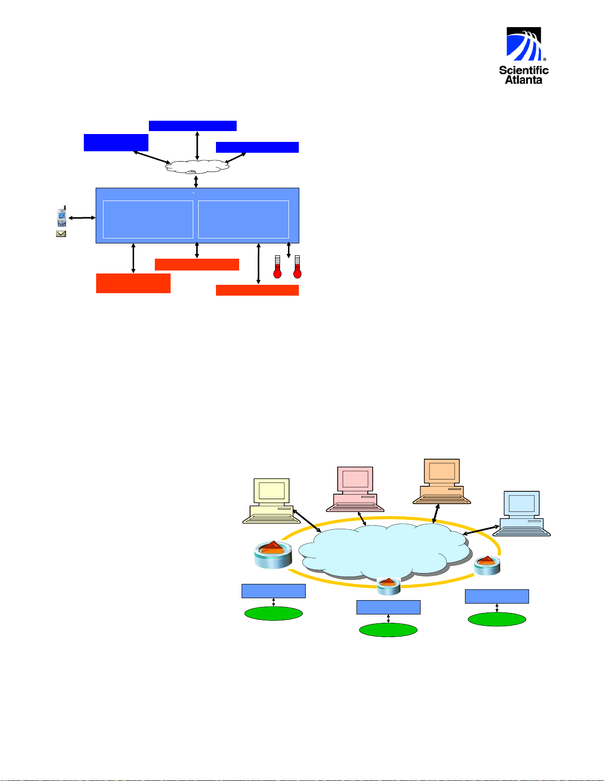
Flexible Client Options
There are four fundamental client options available for the ROSA EM; a simple Web browser, TNCS client, ROSA
NMS client and third party Network Management Systems each designed to meet specific needs of the user.
ROSA EM can be configured to do as much or as little as required to meet the needs of the technicians and
engineers charged with managing the broadband network.
• Simple Web Browser – The user
will open a Web browser window for
each ROSA EM site. This is an ideal
application for small systems that
have only one or two sites with
ROSA EM installed.
• TNCS Client – The TNCS client will
aggregate all of the ROSA EM sites
to produce a single network view
that is easy to understand. In
addition, TNCS will aggregate the
alarms, perform multi-site backup
schemes and retain historical logs
for alarms, system executables, and
software status for all of the ROSA
EM sites.
• ROSA NMS Client – A ROSA client
provides all of the TNCS functionality as well as a relational database that enables the operator to produce
performance and trending reports on the network, the managed devices, and overall system performance.
ROSA also has several modular advanced tasks that provide significant added value to system operators,
engineers and managers.
• Third-Party Client – ROSA EM is ideally suited to integrate into an overall 3
northbound SNMP interface in ROSA EM supports Traps, Gets and Sets allowing the overall NMS to have
control of the managed devices. Launching the Web browser in ROSA EM allows the NMS operator to easily
view the details of any managed device from the operations center.
Web
Browser
ROSA EM
Network Elements
The northbound management interfaces are
composed of:
• Web browser client interface on the ROSA
EM that allows management of network
devices as well as viewing real-time status
and alarms.
• The SNMP agent in ROSA EM provides a
northbound SNMP interface to higher level
Network Management Systems (supports
TRAPS, GETS and SETS).
• Utilizes FTP to remotely upgrade ROSA EM
software as well as the backup and
restoration of ROSA EM configuration data.
ROSA
TNCS
Client
LAN / WAN
Network Elements
ROSA EM
rd
Client
3rd Party
Client
ROSA EM
Network Elements
party NMS via SNMP. The
2
Page 3

ROSA EM - Element Management System
Specifications
Remote Control and Configuration Ports (*)
Ethernet management port
Number of ports
Connector type
Physical layer
LED indication
Dielectric isolation
Note: In case a client (simple Web browser, TNCS client,
ROSA NMS client or third party NMS) is used in combination
with ROSA EM, it must be possible to perform a successful
ping command between ROSA EM and the client in both
directions.
RS-232 Serial Ports
Number of ports
Connector type
Pin layout
Physical layer
Baud rate
Protocol
ESD
RS-232 - RS-485 - RS-422 Serial Ports (configurable)
Number of ports
Connector type
Pin layout
Physical layer
Baud rate
Protocol
ESD
Digital Input Ports
Number of ports
Connector type
Contacts per port
Decision threshold
Input voltage range
ESD
Galvanic Isolated Digital Input Ports
Number of ports
Connector type
Contacts per port
Decision threshold
Differential over voltage protection
Common mode input voltage
ESD
Dielectric isolation
Relay Outputs
Number of ports
Connector type
Contacts per port
Maximum voltage
Maximum load current
Dielectric isolation
Load
External Temperature Sensor
Number of ports
Note: Temperature sensors available as an option.
2
RJ-45
10/100Base-T
LINE and ACT
1.5 kV AC
4
Male, 9 pin Sub-D
Standard DTE
RS-232
Up to 38.4 kbaud
RCDS, SMC or other
Max. 15 kV Performance Criterion B
4
Male, 9 pin Sub-D
Configurable (for RCDS or SMC pin layout refer to user’s
guide)
RS-232, RS-422 or RS-485
Up to 38.4 kbaud
RCDS, SMC or other
Max. 15 kV Performance Criterion B
108
Female, 25 pin Sub-D
2
TTL / CMOS
Max. ± 15 V
Max. 15 kV Performance Criterion B
12
Female, 25 pin Sub-D
2
Low: < 0.8 V, High: > 2 V
Max. ± 15 V
Max. 60 V DC or 42 V AC
Max. 15 kV Performance Criterion B
500 V port to port
24
Female, 25 pin Sub-D
3 (common, normal open, normal closed)
42 V AC / 60 V DC
1 A @ 30 V DC
500 V
Resistive load
2
3
Page 4

ROSA EM - Element Management System
Specifications - continued
Remote Control and Configuration Ports - continued
Analog Inputs
Number of ports
Connector type
Contacts per port
Input range
Type
Resolution
Input impedance
Analog Outputs
Number of ports
Connector type
Contacts per port
Output voltage range
Resolution
Output impedance
Craft Interface
Number of ports
Connector type
Pin layout
Physical layer
Baud rate
ESD
Keyboard and Mouse
Number of ports
Connector type
Pin layout
Physical layer
ESD
Monitor
Number of ports
Connector type
Pin layout
Resolution
(*) Note concerning Safety Extra-Low Voltage (SELV) Circuit Warning
To avoid electric shock and in order to comply with the product’s regulatory safety compliance certifications:
• Do not connect any I/O, signal or communication port to circuits falling beyond the requirements for SELV circuits
• Always verify voltage, current and energy levels of connected circuits against SELV requirements (for a full definition of SELV
requirements, refer to UL, EN or IEC 60950 standards for limit values).
• Ensure that only ‘Digital Input Ports’, Galvanic Isolated Digital Input Ports’ or ‘Relay Outputs’ are connected to outdoor circuits.
Important:
• SELV voltage limits for indoor connections are < 60 V DC (or peak) or < 42.4 V AC RMS.
• SELV voltage limits for outdoor connections are lower than those for indoor connections.
• Outdoor voltages should be no greater than 15 Vrms, 21.2 Vpk, and 30 V DC under normal operating conditions.
• Cabling of outdoor circuits must be shorter than 140 feet or 42 meters.
• In all cases it is needed to protect outdoor cabling by means of a Primary Surge Protector at the position where the wiring enters the
building.
• Outdoor cabling should be routed away and spaced with adequate clearances from power and lighting conductors.
• For installations in the United States, refer to the appropriate sections in the National Electrical Code (NEC).
• For installations in other countries, ensure that the installation complies with the National requirements taking in account the above-
mentioned recommendations.
8
Female, 25 pin Sub-D
2
0 to +15 V by default, configurable to 0 to +60 V
Differential input
8 bit (55 mV step with 15 V input range, 250 mV step with
60 V input range)
> 100 kΩ
2
Female, 25 pin Sub-D
2
0 to +10 V
8 bit (40 mV step)
1 kΩ
1
Male, 9 pin Sub-D
Standard DTE
RS-232
Up to 38.4 kbaud (default 19.2 kbaud)
Max. 15 kV
2
PS/2
Standard PS/2
RS-232
Max. 15 kV
1
DB15H
VGA
Up to 1024 x 768 (SVGA)
4
Page 5

ROSA EM - Element Management System
Specifications - continued
Management Specifications
Number of managed devices depends on license with an absolute maximum of 1000 devices
Maximum number of simultaneously connected web browser sessions is 12
Maximum number of simultaneously connected TNCS clients is 8
Environmental Specifications
Within specs +10°C to +45°C / +50°F to +113°F
Operating temperature 0°C to +50°C / +32°F to +122°F
Storage temperature -20°C to +70°C / -4°F to +158°F
Power Supply AC
Nominal voltage range
Full voltage range
Ripple & Noise
Maximum power consumption
Power Supply DC
Nominal voltage
Ripple & Noise
Maximum power consumption
Mechanical Specifications
Height 88 mm / 3.48 in. (2 RU)
Width 482 mm / 19 in.
Depth 470 mm / 18.5 in.
Weight Approx. 5 kg / 11.02 lbs
100 – 240 V AC
90 – 264 V AC, 47 - 63 Hz
Compliant with ETSI ETS 300-132-1
25 W
-48 V DC
Compliant with ETSI ETS 300-132-2
25 W
5
Page 6

ROSA EM - Element Management System
Ordering Information
ROSA EM – North and Latin America
ROSA EM AC version
ROSA EM, 100 - 240 V AC US, DCL Class 1 (0-10 devices) 4005326
ROSA EM, 100 - 240 V AC US, DCL Class 2 (0-25 devices) 4005370
ROSA EM, 100 - 240 V AC US, DCL Class 3 (0-50 devices) 4005371
ROSA EM, 100 - 240 V AC US, DCL Class 4 (0-100 devices) 4005372
ROSA EM, 100 - 240 V AC US, DCL Class 5 (0-250 devices) 4005373
ROSA EM, 100 - 240 V AC US, DCL Class 6 (0-500 devices) 4005374
ROSA EM, 100 - 240 V AC US, DCL Class 7 (0-750 devices) 4005375
ROSA EM, 100 - 240 V AC US, DCL Class 8 (0-1000 devices) 4005376
ROSA EM DC version
ROSA EM, -48 V DC US, DCL Class 1 (0-10 devices) 4006322
ROSA EM, -48 V DC US, DCL Class 2 (0-25 devices) 4007210
ROSA EM, -48 V DC US, DCL Class 3 (0-50 devices) 4007211
ROSA EM, -48 V DC US, DCL Class 4 (0-100 devices) 4007212
ROSA EM, -48 V DC US, DCL Class 5 (0-250 devices) 4007213
ROSA EM, -48 V DC US, DCL Class 6 (0-500 devices) 4007214
ROSA EM, -48 V DC US, DCL Class 7 (0-750 devices) 4007215
ROSA EM, -48 V DC US, DCL Class 8 (0-1000 devices) 4007216
ROSA EM – EMEA (Europe, Middle-East, Africa) and AP (Asia, Pacific)
ROSA EM Headend
ROSA EM Headend, 100 - 240 V AC EU DCL Class 5 (0-250 headend devices) 4005317
ROSA EM Headend, 100 - 240 V AC UK DCL Class 5 (0-250 headend devices) 4005320
ROSA EM Headend, 100 - 240 V AC AUS DCL Class 5 (0-250 headend devices) 4005323
ROSA EM Headend, -48 V DC DCL Class 5 (0-250 headend devices) 4007217
ROSA EM Hub & HFC
ROSA EM Hub & HFC, 100 – 240 V AC EU DCL Class 6 (0-500 Hub & HFC network devices) 4005318
ROSA EM Hub & HFC, 100 – 240 V AC UK DCL Class 6 (0-500 Hub & HFC network devices) 4005321
ROSA EM Hub & HFC, 100 – 240 V AC AUS DCL Class 6 (0-500 Hub & HFC network devices) 4005324
ROSA EM Hub & HFC, -48 V DC DCL Class 6 (0-500 Hub & HFC network devices) 4007218
ROSA EM Transmitter sites
ROSA EM Tx Site, 100 – 240 V AC EU DCL Class 1 (0-10 devices in transmitter sites) 4005319
ROSA EM Tx Site, 100 – 240 V AC UK DCL Class 1 (0-10 devices in transmitter sites) 4005322
ROSA EM Tx Site, 100 – 240 V AC AUS DCL Class 1 (0-10 devices in transmitter sites) 4005325
ROSA EM Tx Site, -48 V DC DCL Class 1 (0-10 devices in transmitter sites) 4007219
ROSA EM Upgrades
ROSA EM Device Count License (DCL) Upgrade 4005377
Class Info
DCL Class 1 : 0-10 devices
DCL Class 2 : 0-25 devices
DCL Class 3 : 0-50 devices
DCL Class 4 : 0-100 devices
DCL Class 5 : 0-250 devices
DCL Class 6 : 0-500 devices
DCL Class 7 : 0-750 devices
DCL Class 8 : 0-1000 devices
ROSA EM Options
ROSA EM external temperature sensor, maximum 2 per ROSA EM
(cable length 15 m / 50 ft)
Part Number
Part Number
Part Number
Part Number
4005382
6
Page 7

ROSA EM - Element Management System
Ordering Information - continued
Related Products
Cable Kits
For Scientific-Atlanta TNCS devices and RCDS devices, refer to the corresponding cable kits.
ROSA Network Management System
Components for ROSA Network Management System
Performance Logging Task V9529450
Performance Data Compression Task V9529652
Service Availability Reporting 7001733
SNMP Manager Runtime License (runs custom SNMP profile drivers) V9529615
SNMP Profile Manager (includes one SNMP Manager Runtime license) V9529616
Group-wise Equipment Manager V9529823
UDD Runtime License (runs custom Universal Device Drivers) V9529595
UDD Profile Manager (includes one UDD Runtime license) V9529610
Note: Reporting Component is part of the basic ROSA package
Copernicus MKIV ROSA Network Management Server
COPERNICUS ROSA Network Management Server 100-120/200-240 V AC Std
Standard SQL database (MSDE)
Including RS-232/4 and RS-485/4, ROSA 3.X Client, license for 250 points V000112011
COPERNICUS ROSA Network Management Server 100-120/200-240 V AC LS
Large System SQL database (MS SQL Server 2000 Standard Edition)
Including RS-232/4 and RS-485/4, ROSA 3.X Client, license for 250 points
TNCS Client
Software
TNCS Software, Version 2.0 4006663
Desktop Computer (Optional)
Computer, Server, Mini-tower, Includes: 17" Monitor, Speakers, Keyboard, CD Writer, Ethernet Card,
56KModem, Windows 2000
Rack Mount Computer (Optional)
Computer, Server, Rack Mount, Includes: Ethernet Card, Internal 56K Modem, CD Writer, RS-458/422
PCI Card and Windows 2000 (4 RU)
Rack Mount Keyboard & 17" Monitor (Optional)
Keyboard, Rack Mount, with Touchpad and Mounting Hardware (1 RU) 730165
Monitor Cabinet, Rack Mount, for 17" monitor, (11 RU) 735741
Monitor, 17" with Internal Speakers 738034
Rack Mount Keyboard & Flip-up Monitor (Optional)
Keyboard, Rack Mount, with Flip-up Monitor, Touchpad, & Mounting Hardware (2 RU) 735740
Power Cord
Power Cord, European 747746
Scientific-Atlanta and the Scientific-Atlanta logo are registered trademarks of Scientific-Atlanta, Inc.
ROSA and Copernicus are trademarks of Scientific-Atlanta Europe NV.
Specifications and product availability are subject to change without notice.
© 2004 Scientific-Atlanta, Inc. All rights reserved.
Part Number 7003710 Rev F
September 2004
Part Number
V000112021
Part Number
738693
735727
Distributed by: Mega Hertz 800-883-8839 sales@go2mhz.com www.go2mhz.com
7
 Loading...