

Page 1
Lii
L
THE ADVANCED SECURITY & AUTOMATION SYSTEM
FOR YOUR HOME & BUSINESS
f
f
e
e
S
S
O
O
S
S
Model LS-30
OPERATION MANUAL
V5.23
Page 2

Table of Contents
Page
INTRODUCTION & INSTALLATION --------------------------------------------------------- 1
BASE UNIT -------------------------------------------------------------------------------------- 3
STATUS INDICATORS ------------------------------------------------------------------------ 4
ELECTRICAL INSTALLATION ------------------------------------------------------------- 5
MECHANICAL INSTALLATION --------------------------------------------------------- 6
USER OPERATION -------------------------------------------------------------------------------- 7
START OPERATION -------------------------------------------------------------------------- 9
(2) System Check ------------------------------------------------------------------------------ 10
(2-1) Telephone Number Check ---------------------------------------------------------- 11
(2-2) Voice Check -------------------------------------------------------------------------- 12
(2-3) Device Check ------------------------------------------------------------------------ 12
(3) Master Mode -------------------------------------------------------------------------------- 13
OPERATION MODES OF LS-30 ----------------------------------------------------------- 15
REACTION OF LS-30 TO DIFFERENT ALARMS ------------------------------------- 16
ANSWERING THE CALL FROM LS-30 ------------------------------------------------- 17
DIAL-IN CONTROL ------------------------------------------------------------------------- 18
INSTALLER & CMS SETTINGS ----------------------------------------------------------------- 19
(4) Installer Mode ------------------------------------------------------------------------------ 20
(4-1) Set Timer --------------------------------------------------------------------------- 20
(4-2) Set Telephone ---------------------------------------------------------------------- 22
(4-2-1) Set Telephone Number -------------------------------------------------- 24
(4-3) Set Sound --------------------------------------------------------------------------- 26
(4-4) Set Device -------------------------------------------------------------------------- 28
(4-4-1) Change Device Setting ------------------------------------------------- 29
(4-5) Set Siren ---------------------------------------------------------------------------- 31
(4-6) Set Misc. --------------------------------------------------------------------------- 32
(5) CMS Mode --------------------------------------------------------------------------------- 33
SPECIFICATIONS--------------------------------------------------------------------------------- 34
APPENDIX ------------------------------------------------------------------------------------------- 35
A-1, In-coming Message Display.
A-2, Connection Diagram for USB or RS-232 Computer Interface
A-3, Connection Diagram for Ethernet Adaptor and Internet Remote Access
A-4, Connection Diagram for X-10 Power Line Interface
A-5, Terminal Board Connection
A-6, Using the Same Telephone Line to Connect LS-30, Fax Machine and Telephone
Answering Machine
A-7, Partial Arm for Group Numbers “91” to “99”
Page 3

INTRODUCTION & INSTALLATION
1
Page 4

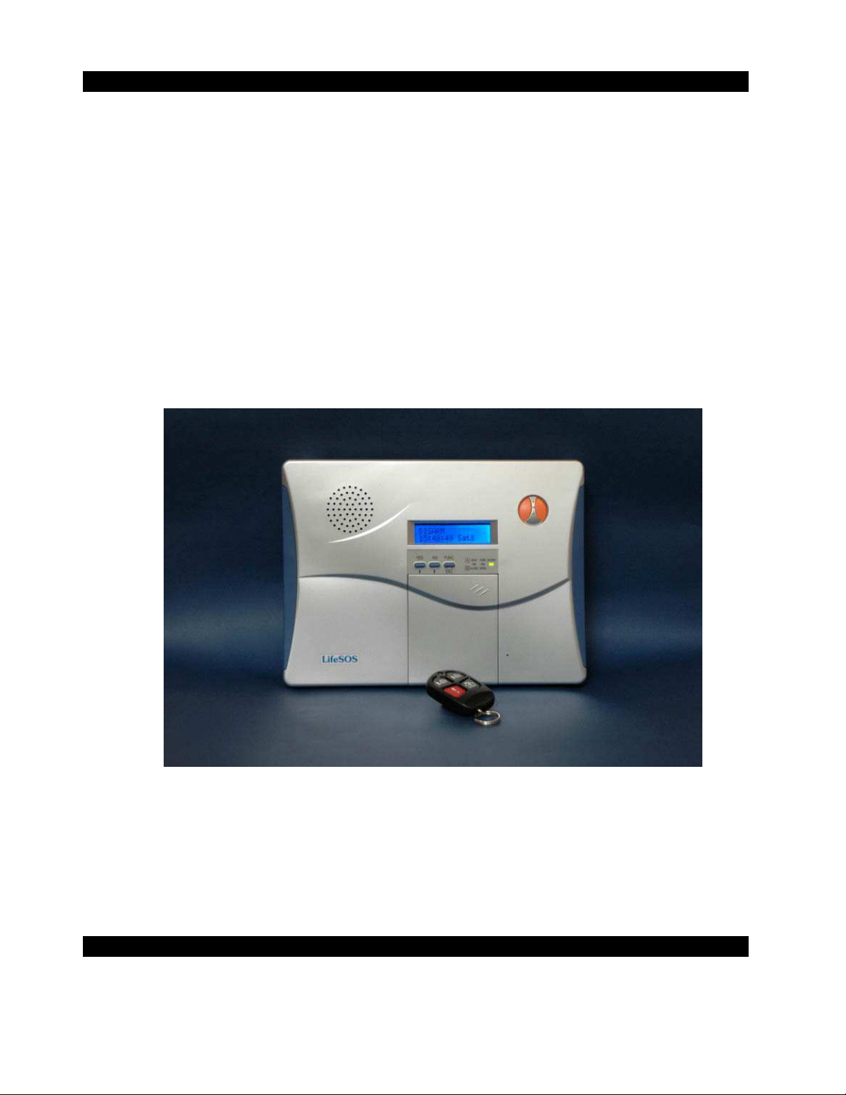
Thank you for purchasing the LS-30 IP Based Wireless Security & Automation Control System.
By adopting modern microprocessor control and communication technologies, the LS-30 is designed to
provide all the most advanced features that you need to protect your home and business. Moreover, you
can operate the system and read its status by using the proprietary GUI (Graphic User Interface)
HyperSecureLink through the Internet, from all over the world. The LS-30 is not only a security system
but also an automation controller that allows you to set as many as 15 programmable switches to execute
daily commands throughout a whole week. With optional environmental sensors and auto-control switches,
the LS-30 also operates as an environmental monitor/control center to record all the environmental data
and save your energy consumption automatically.
Although the LS-30 is a very powerful device, thanks to the interactive HMI (Human Machine Interface)
programming technology, its operation is simple. Just follow the instructions shown on the LCD display
by answering the questions with YES/NO buttons or pressing the correct keys, and the settings are done.
You can also set up the system on your laptop or PC using the optional USB/RS-232 adapter and
HyperSecureLink software.
The set up is simple, switch on back up battery, connect the Base Unit to power, enroll sensors and
accessories, connect the telephone line, set the telephone numbers and record the voice messages, and then
the LS-30 is at your service.
As your security requirements grow and you become more familiar with the system, you can expand and
accessorize the LS-30 to meet your specific needs. Simply call your local dealer; trained professionals can
answer any questions you have regarding additional accessories.
Main Features:
Smart Home System with Security, Environment monitoring/ control and energy saving.
Computer and Internet interface to set, download and upload system parameters and events.
Interactive programming with 16 x 2 LCD display.
Detailed 512-event log with time tag.
288 sensors/ zones can be accommodated with15 programmable switches.
Receiving RF signal strength indication and jamming detection.
Robust multi-million RF coding and special transmission timing design, avoiding interferences.
Responds to panic, burglary, fire, medical alarm and environmental hazards.
Burglar zones with supervised sensors, door and window open/ close detection.
Special Monitoring mode to record all the activities in the protected area without triggering the alarm.
9 independent partial arm zones, one LS-30 can operate as 10 independent burglar alarm systems.
Automatic operation and switch control by schedule and scene settings. (Only can be set by computer.)
Built-in voice dialer stores up to 10 phone numbers, 1 pager and 2 CMS data links.
Hands-free speakerphone, two-way voice communication.
Dial-in control of listen-in, 2-way communication, arm, disarm, event report and switch control.
Latchkey function to inform parents when kids leave or return home.
AC power loss and restore will inform the user by voice.
Inactivity monitoring to take care of the elderly or physically challenged at home.
Remote access through Internet by Ethernet Adaptor or through PSTN by Data Communication Module.
Alarm report through Internet with fast response and saving communication charges.
(Ethernet Adaptor & Data Communication Module are optional devices.)
2
Page 5
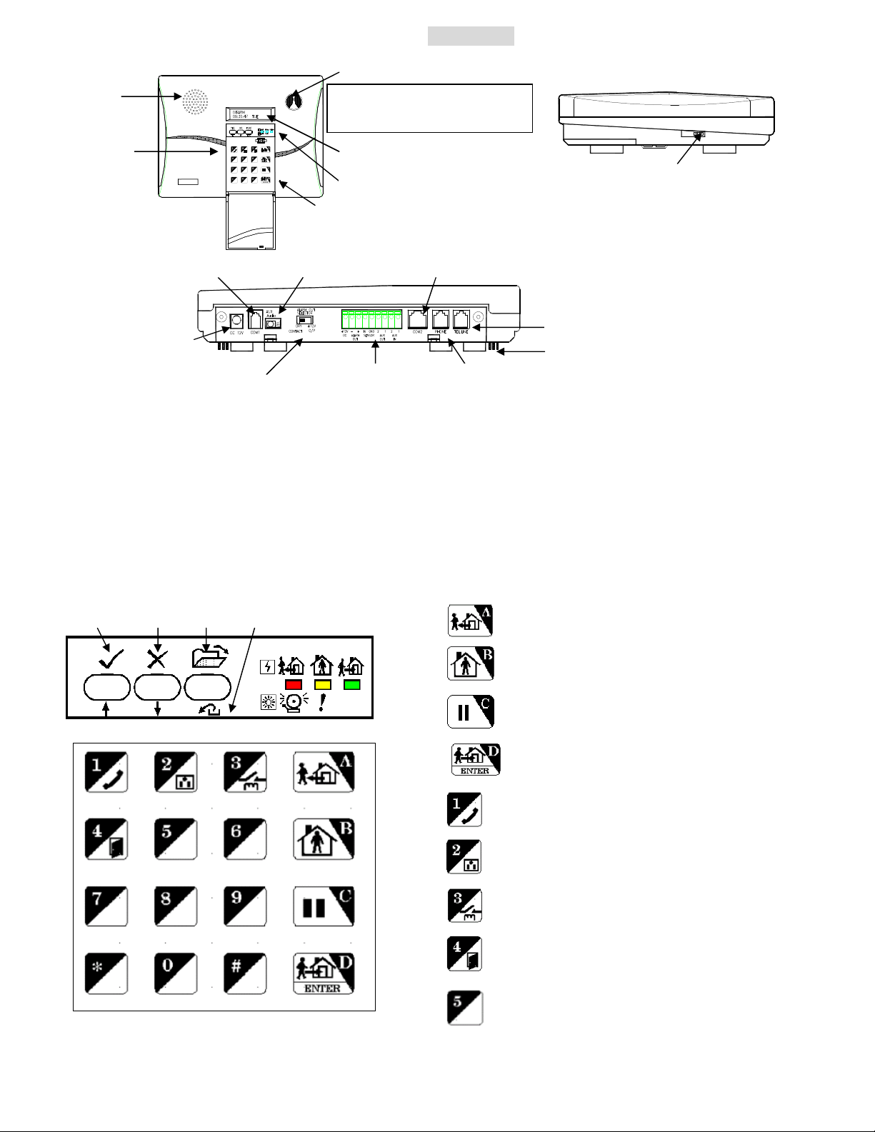
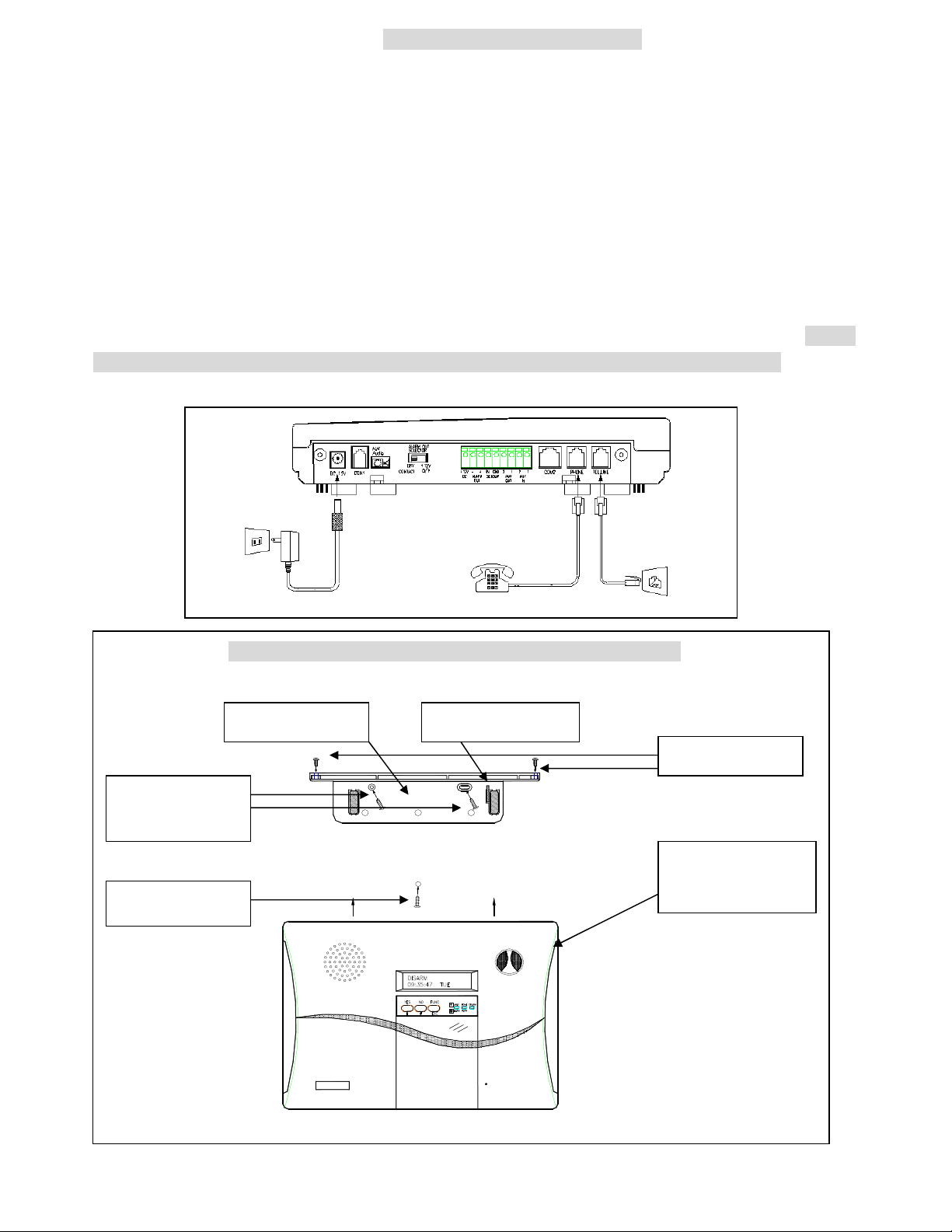
BASE UNIT
LED status
To trigger the Emergency help
,
Telephone Line I/P
Phone Set Connector
Wire Duct
3.COM1
4.COM2
5.AUX. Audio
YES NO FUNC / ESC
Front Panel Side Panel
Speaker
Emergency Buttons
press both buttons simultaneously.
Key Board
LCD Display
Speaker Volume Control
Rear Panel
Microphone
Power adaptor I/P
1.ALARM OUT SELECTOR
2. Terminal Board
1. ALARM OUT SELECTOR: Set the Alarm Relay Output terminals as DC output or dry contacts when the
relay activates.
2. Terminal Board (Refer to the APPENDIX A-5): One pair of Alarm Relay output, +12VDC (12~15V
/300mA max.) output and ground terminal, three wire sensor inputs, two Aux. outputs.
3. COM1 (Refer to the APPENDIX A-2, A-3): Communication port for USB/RS-232 Adaptor, Ethernet
Adaptor and Data Communication Module.
4. COM2 (Refer to the APPENDIX A-4, A-6): Communication port for Relay Module (XRM-01)/X-10
Power Line Interface Controller.
Key Board & Status Display
Key A & AWAY ARM
Key B & HOME ARM
Key C, STATUS CLEAR & PAUSE
Key D, DISARM & ENTER
Key 1 & Hands-free Telephone
Key 2 & Switch Control
Key 3 & Alarm Relay Control
Key 4 & Door Open (Reserved)
Key 5 & message in reading (Refer to A-1)
3
Page 6
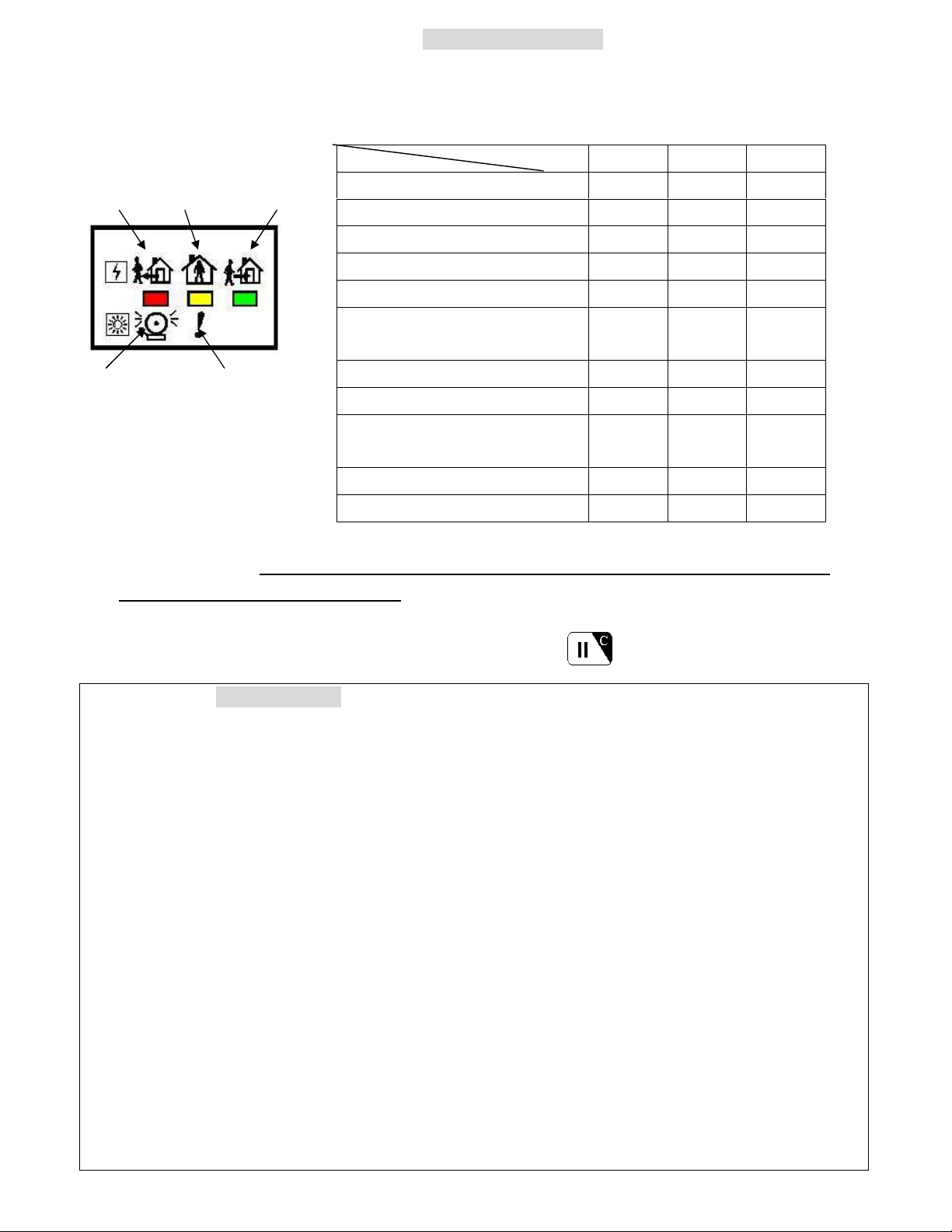
STATUS INDICATORS
There are three LED indicators in green, yellow and red colors on the front panel. They represent the system
operation mode and alarm/ warning status as listed in the following table.
State LED Red Yellow Green
AWAY HOME DISARM
DISARM OFF OFF Flash
HOME OFF Flash OFF
AWAY Flash OFF OFF
DISARM with Warning Message OFF ON Flash
DISARM with Alarm Message ON OFF Flash
ALARM WARM
DISARM with Warning & Alarm
Message
HOME with Warning Message OFF ON OFF
HOME with Alarm Message ON Flash OFF
HOME or AWAY with Warning
& Alarm Message
AWAY with Warning Message Flash ON OFF
AWAY with Alarm Message ON OFF OFF
ON ON Flash
ON ON OFF
Note: If there is any pending alarm message in the event log memory, the ALARM indicator (red LED)
will be lighted and a warning “Dong” sound will be issued in every 5 minutes to alert the user
when the system is in Disarm Mode (Refer to (4-3) Set Sound-Alarm Warning). The indicator
(red LED) and the warning sound will be turned off after the user runs the Event Check function
(Refer to (2) System Check-Event Check) or press (Hotkey) to clear the status indicator
in Disarm Mode.
Sensors & Zones (All sensors are divided into five main categories)
1. 32 Controller /Panic Devices (C): Remote Controller, Keypad, Card Reader.
2. 128 Burglary Sensors/Sirens (B): Door Magnet, PIR (Passive Infrared), Glass Break Detector,
Vibration Sensor, Pressure Change Detector, Wireless Siren.
3. 64 Fire Sensors (F): Smoke/Heat/Flame Detector, CO Detector, Gas Detector, Fire Call Point.
4. 32 Medical Help Transmitters (M): Medical Button, Inactivity Detector.
5. 32 Special Sensors (S): Temperature/Humidity Sensor, Flood,/Light Detector, Analog/Power Meter.
All the sensors are numbered with two double-digit zone numbers from (01-01) to (99-99), the first
two-digit number is the Group number and the second two-digit number is the Unit number, set by
the Installer in the initial installation.
Ex.1, C 01-02: Controller number 01-02 (Group number 01, Unit number 02).
Ex.2, B 02-04: Burglar Sensor number 02-04 (Group number 02, Unit number 04).
Group number: The user can group several sensors by using the same Group Number. For
example, the sensors in the first floor can be assigned as group number “01” and the sensors in
the second floor can be assigned as group number “02”.
Note: Special group numbers
”00” for Base Unit (Z), “80” to “89” for Xkeypad (C) , “90” for status indicator (Special Sensor).
“91” to “99” for the Partial Arm Zones (Z) (Please refer to APPENDIX A-8).
4
Page 7
Battery Switch
Battery 1
Battery 2 (optional)
ELECTRICAL INSTALLATION
1. Switch on the internal rechargeable battery.
Turn over the Base Unit, open the battery compartment
and push the battery switch to the ON (UP) position.
Note: If external power fails, the internal backup batteries can
supply operational power to the Base Unit for 15 to 26 hours,
depending on the battery type in the Base Unit.
The LS-30 Base Unit can accommodate 2 rechargeable battery packs.
Battery pack 1 is 9.6V/800mA(built-in) and Battery pack 2 (optional) is 9.6V/600mA, providing 15-26
hours back up time.
2. Plug in the power adaptor.
3. Key in the Installer password. (The default Installer password is “1234”.)
(Refer to the Passwords Block in page 8.)
4. Enter the Installer Mode. (Refer to (4) Installer Mode).
5. Program the basic settings
a) Telephone numbers (Refer to (4-2) Set Telephone – (4-2-1) Set Telephone Number)
b) Record voice message
(Refer to (4-3) Set Sound-Record Voice)
c) Enroll all the wireless devices by registering their ID codes in the Base Unit.
(Refer to (4-4) Set Device-Enroll Device)
6. Set other functions if necessary.
7. Connect the telephone line
APPENDIX A-6), Data Communication Module or Ethernet adaptor (if remote access is needed, refer
to the APPENDIX A-3).
Note: For Data Communication Module and Ethernet adaptor, please refer to their user guides.
8. Install the Wireless Siren and register the Base Unit’s ID code into the Wireless Siren.*
* This is only needed for the system equipped with optional Wireless Siren.
(Refer to (4-5) Set Siren-Siren/Relay Test and the instructions of the Wireless Siren)
9. Enter into Master Mode and adjust the clock. (Refer to (3) Master Mode – Set Clock)
10. Test other functions, if any have been set.
For details, please read the description on the following pages carefully.
All the above settings also can be done through the proprietary GUI program “HyperSecureLink”.
Please refer to the “HyperSecureLink” User Guide.
5
Page 8
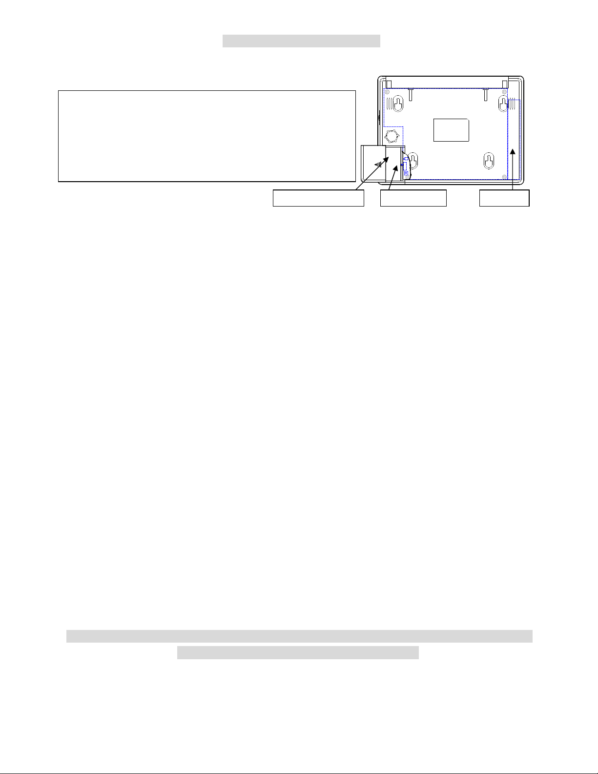
MECHANICAL INSTALLATION
1
. Attach the
3
2
. Insert the screw
Placement of the Base Unit
It is important for the Base Unit to have a good reception quality for the RF signals transmitted from all the
sensors and controllers.
Place the Base Unit around the central area at your home or business if possible.
Keep the Base Unit away from large appliances and other metal objects.
Locate the Base Unit near a power outlet and a telephone socket (if telephone line is needed.).
Install the Door Sensors, PIR and all the other sensors according to your site planning.
Check the radio signal quality from the RSSI (Receiving Signal Strength Indication) reading on the LCD by
pressing the test button on the sensors. Relocate the sensors/Base Unit to get the best reading (dB number) if
necessary. If the dB number is less than 40dB (Standard Version) then you should adjust the location
of the sensors/Base Unit or add a RF Repeater to the system to extend the RF operation range. (Do not
attach the transmitter on a metal surface; this will shrink the RF signal transmission range.)
Plug in the AC adaptor and telephone line.
Attach the Base Unit to the wall using the Mounting Bracket
Mounting Bracket Tamper Switch Cam
4.Tighten the screws
Mounting Bracket
on the wall.
. Attach the Base
Unit to the Mounting
Bracket and push up.
for the keyhole
6
Page 9

USER OPERATION
7
Page 10
The HMI (Human Machine Interface) of the LS-30 adopts the interactive programming technique, so
that all settings and operations can be done very easily just by answering YES or NO and
following the instructions on the display to enter figures.
Using the HMI
If the LCD shows a question mark (?), just answer by pressing the YES or NO button.
Ex: The LCD shows Master Mode? , Press the YES button to enter into Master Mode.
If the LCD shows the word Enter then key in proper figures followed by the Enter (D) key.
Ex: The LCD shows Seconds(0-255)
Enter:
The system asks the user to enter the figures between 0 and 255 and then press the Enter (D) key.
(If the user keys in 6 , 4, D, it means the timer is set at 64 seconds).
For all the Check functions, use the ↑ and ↓ keys to scroll up and down the screen.
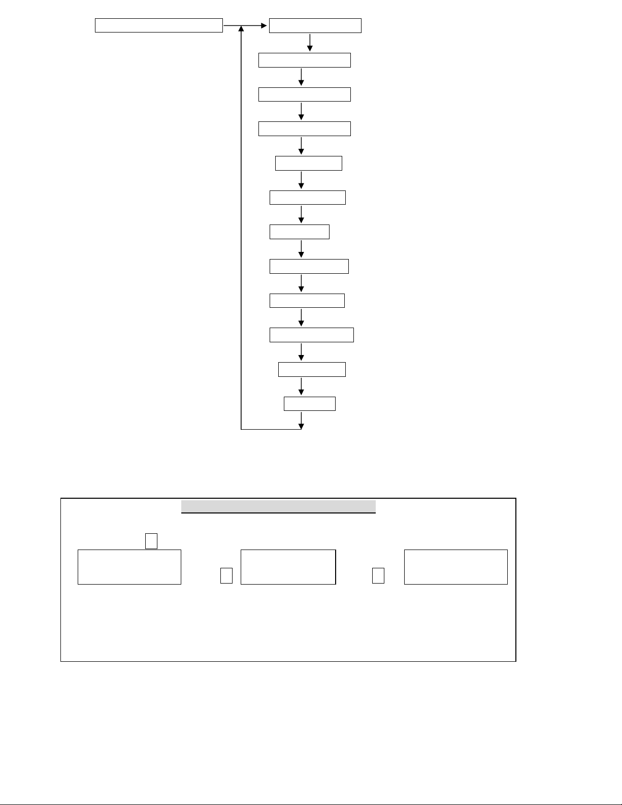
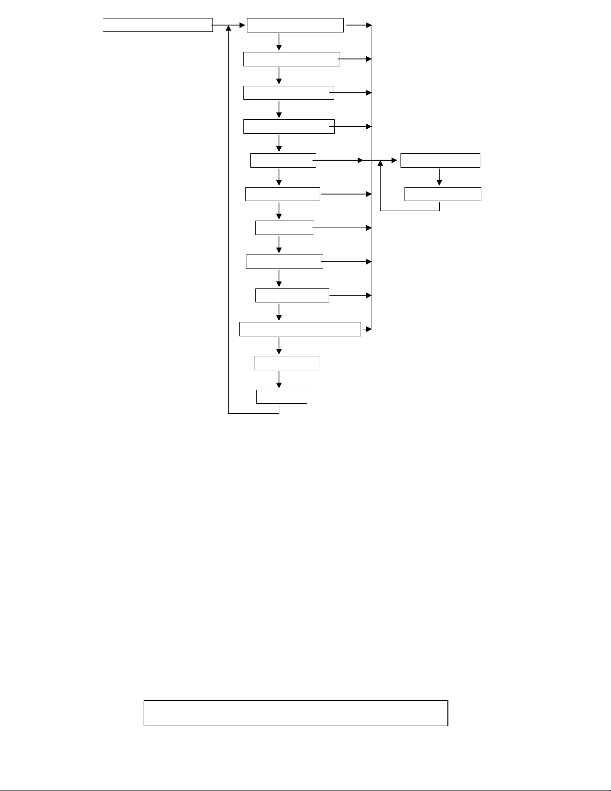
Reading the programming flow chart
State A State A-1
Down arrow
Select the next state
State Loop A State A-2 Sub-state of State A-2
State A-3
Right arrow
Enter into the sub-state
Note: Pressing FUNC/ESC at any time will let you leave the current state loop.
Password
As many as 14 passwords can be set in the system, each with a max. of 8 digits.
Master Password (User1, default”0000”): The user with this password is authorized to manage
the other user passwords and user settings.
7 General User Passwords (User 2- 8): Open to 7 general users; with any of these passwords a
user can change operation modes, and check all the system status.
2 Latchkey User Passwords (User 9-10): User 9 and User 10 are also called Latchkey Users.
The LS-30 will dial the Latchkey Number (Refer to (4-2-1) Set Telephone Number-
Latchkey Number) when these users arm or disarm the system.
*Duress Code (User 11,default “8862”): Using this code to operate the system, the LS-30 will
send a duress signal to the CMS.
Installer Password (default”1234”): The user with this password is authorized to enter into the
Installer Mode.
2 CMS Passwords (CMS1 default “1111”, CMS2 default “2222”): Open to 2 CMS stations for
CMS parameter setting and system check.
8
Page 11
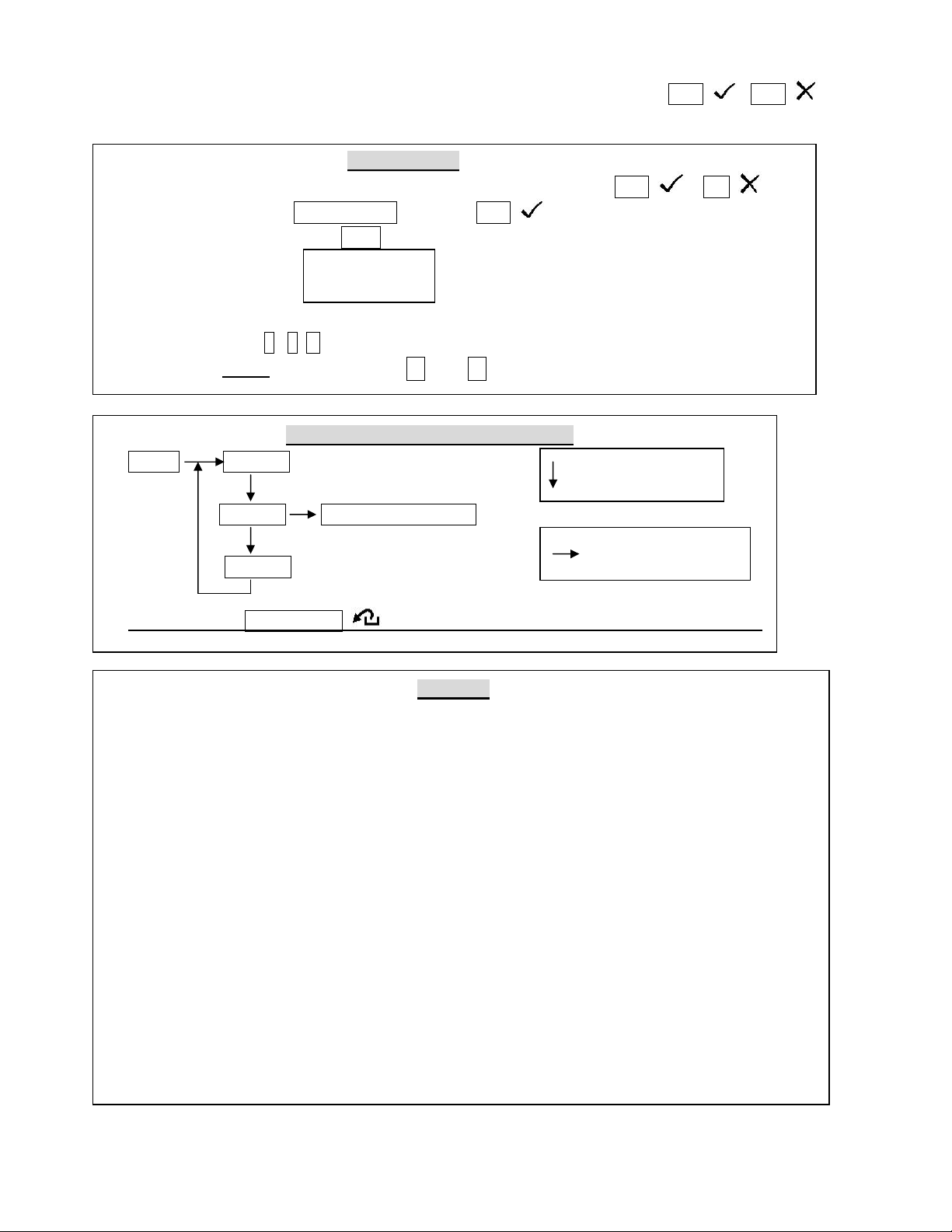
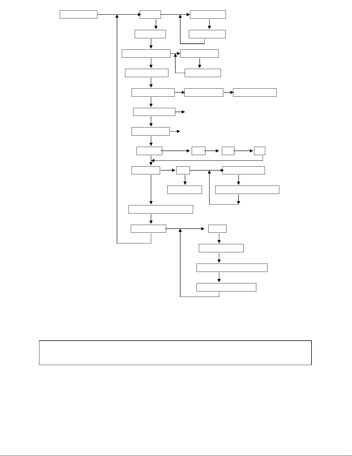
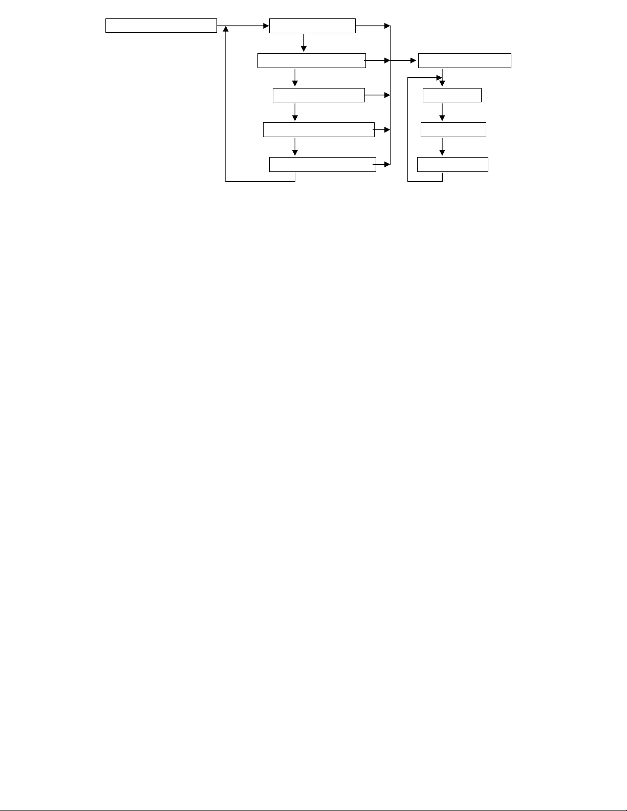
START OPERATION
Enter hands
-
free Telephone Mode. The Base Unit can be used as a hands
-
free
When you apply the power to the LS-30 for the first time, the LCD display shows “System Reset”
& time information. This informs the user about the time of system power on. User can key in
“0000DC” to clear the display and entering the Initial State.
After entering the password, the user can select System Check function, Hot Key Control function or enter
Master, Installer and CMS modes.
Initial State
(*Only valid in Disarm Mode)
Master or User Password
Installer or CMS Password
Hot Key Process System Check? Or Press Hot Key System Check?
Hot Key Enter Yes No Yes No
System Check Master Mode Installer Mode CMS Mode
(2) (3) (4) (5)
Hot Key: By pressing the keys below, you can enter into the specific operation mode directly.
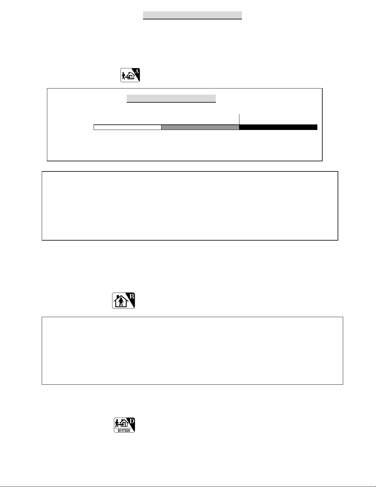
Enter AWAY Mode. (Quick Away: Press the key for 2 seconds to enter AWAY Mode from “Disarm”.
Ignore the password request.)
Enter HOME Mode. (Quick Home: Press the key for 2 seconds to enter Home Mode from “Disarm”.
Ignore the password request.)
Clear LED/LCD alarm/warning status, reset siren and stop dialing immediately.
Enter DISARM Mode & reset siren.
telephone for 10 minutes when you enter this mode.
Press ESC to disconnect and return to normal operation.
Switch control (XRM-01 Relay Module and X-10 switch control module are optional.)
Close or open the alarm relay terminals on the rear panel.
Open Door (reserved).
Reading Come-In-Message (Refer to Appendix A-1)
For AWAY, HOME & DISARM Modes - refer to the OPERATION MODES OF LS-30.
The ARM Mode in this manual means AWAY or HOME Mode.
9
Page 12
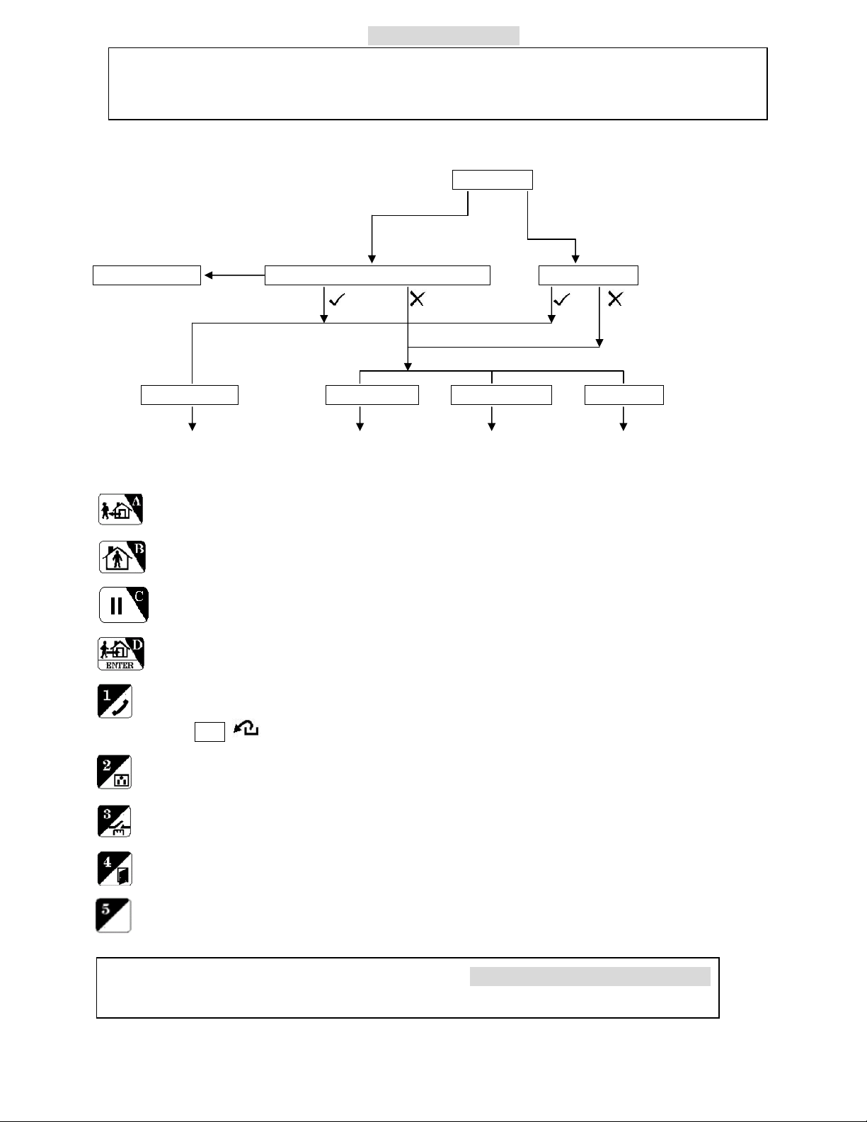
(2) System Check Event Check Check By Sequence
Check By Date
Telephone Number Check (2-1)
Voice Check (2-2)
Device Check (2-3)
Event Check: The Base Unit can store 512 event records in its memory. These events can be checked by
time sequence or by entering the date information. Use the ↑ and ↓ keys to scroll up and down
the events.
.
Reading Event Log from the LCD Display
Ex.1: LCD shows C02-03 Disarm
04/26 22:08 01
The Controller (C) numbered 02-03 set the system in Disarm state at 04/26 22:08;
this is the latest event (Event # 01).
Ex.2: LCD shows B01-02 Burglar
01/13 19:32 253
The Burglar sensor (B) numbered 01-02 issued a burglar alarm at 01/13 19:32,
this event is numbered as 253.
Ex.3: LCD shows Z00-11 Disarm
12/22 08:00 03
The Master (user number 1) enters the Base Unit (Z) into Disarm state at 12/22 08:00 from
Keyboard, this event is numbered as 03.
Note: All the events generated by the Base Unit are marked with Zgg-uu.
gg = 00 (Event of Base Unit itself), gg = 91-99 (Event of partial zones.)
uu = 0x (Event of Base Unit itself),
x=0 (Base Unit), x=1 (Aux1 I/P), x=2 (AUX2 I/P), x=3 (Sensor In),
x=5 (Emergency Button), x=6 (Inactivity)
uu = 1y (Command from keyboard, y = User number.)
uu = 2y (Command from Remote, like Dial-in control, USB/RS-232 or Internet.)
y=1 (master), y=2-8 (user 2-8), y=9,0 (latchkey users), y=b (Duress),
y=c (Installer), y=d (CMS1), y=e (CMS2), y=f (User can’t be specified)
10
Page 13
(2-1) Telephone Number Check Common 1 Number
Common 2 Number
Common 3 Number
Common 4 Number
Panic Number
Burglar Number
Fire Number
Medical Number
Special Number
Latchkey Number
Pager Number
Pager Data
Show the telephone numbers stored in the memory and their answering types. (refer to (4-2-1) Set Telephone
Number to check the usage of different telephone numbers).
Reading the Telephone Number Display
If the telephone number is over 16 digits, it will be divided into two parts to be shown on the
screen, use the ↓ key to check the lower part of the number.
Common1 Common1 Common2
123456789012345- Press ↓ -6789V Press ↓ 2222222222T
The above example shows that the Common 1 number is: 1234567890123456789, and
Answering is set by Voice.
The V or T following the last digit of the telephone number indicates whether the answering
status is Voice or Tone. (refer to (4-2-1) Set Telephone Number.)
11
Page 14

(2-2) Voice Check All Voice
Mag.Sensor 07
Common Segment
Panic Segment
Burglar Segment
Fire Segment
Medical Segment
Special Segment
Latchkey Disarm Segment
Latchkey Away Segment
Playback the pre-recorded voice messages. (refer to (4-3) Set Sound to check the usage of different segments
of the voice messages).
(2-3) Device Check Controller
Burglar Sensor
Fire Sensor Check By Sequence
Medical Button Check By Zone Number
Special Sensor
Check the current status of all the devices, using the ↑ and ↓ keys to scroll up and down the number.
Reading the Device Status Display
Ex.1 Remote Ctl. 02 The number 2 Controller is a Remote Controller, Zone number is
C01-02 Normal 01-02, and status is normal.
Ex.2 The number 7 Burglar sensor is a Magnetic sensor, Zone number is
B10-12 Trouble
10-12, 10-12, with some kind of trouble. (go to (2) System Check-Event
Check to check what kind of trouble happened to this sensor.)
12
Page 15
(3) Master Mode Set Bell Door Bell On
Device Test Door Bell Off
Set Monitor Mode Monitor Mode (Only can be entered in Disarm Mode)
Set Partial ARM Disarm Mode
COM1 Control COM1 On/Off Need Password?
Set Entry Delay (Refer to (4-1) Set Timer- Set Entry Delay.)
Set Exit Delay (Refer to (4-1) Set Timer- Set Exit Delay.)
Set Clock Time Date Day
Set Switch X-10 Set House Code
Type2-Type5 Set Switch Auto Control
(Reserved)
*Deny Arm if not Ready
Set Password Master
User 2 ~ User 8
User 9, 10 (Latchkey User)
User 11(Duress Code)
Bell ON/OFF (default= ON): Enable/Disable the doorbell chime.
Bell ON: In Disarm Mode, the Base Unit will issue a doorbell sound (Ding! Dong!) when receiving a
triggering signal from a Burglar sensor with its Bell ON/OFF status set in the ON state.
Bell OFF: No doorbell chime will sound.
Note: The Bell function only works for the Burglar Sensor if its Bell ON/OFF status is set in the ON
state. (refer to (4-4-1) Change Device Setting-Burglar Sensor-Enable State-Bell ON/OFF.)
Device Test: The system opens a 5-minute test window for the user to test the operation of all the sensors
(not including the Remote Controller and Keypad). In this period, when the Base Unit receives any
signal from the sensors, it will only sound beeps and not trigger any alarm. When the 5 minutes are
over, the system returns to its original operation mode automatically. The system will escape from the
test mode immediately when it receives an Arm/Disarm signal.
13
Page 16

Monitor Mode: In this mode all the trigger signals from the Burglar Sensors (not including the sensors
assigned in Group number 91-99 Partial Arm Zones) will be recorded in the Event Log as trigger
signals only; no alarm will be issued. The purpose of this mode is for the recording of all activities in
the protected area while in Disarm Mode. The system will return to Disarm Mode only by changing
state in this setting or from COM1 port command.
Set Partial ARM:
Groups 91 to 99 are nine independent protected zones and these zones can be Armed /Disarmed
individually. (Please refer to APPENDIX A-8)
Set COM1 Control: (default Enable, No Need Password)
Control Enable: The COM1 interface is open for the user to access the system.
Need Password: Password (Only Master and CMS passwords can access the LS-30.) must be
attached to the control commands from the COM1 port.
(If “Need Password” is set on the Base Unit then the password must be set when
running the HyperSecureLink software also. Refer to “HyperSecureLink” User
Guide.)
No Need Password: No password needed for the control commands from the COM1 port.
Control Disable: The COM1 port interface is closed.
Note: If this setting is disabled. The Base Unit can’t communicate with the RS-232/USB
Adaptor, Data Communication Module and Ethernet Adaptor.
Set Switch (Default X-10 type):
X-10 Type: House Code <A-P>: (default <A>)
This code should be the same as the House Code set on the X-10 switches, user can select from
A to P.
Set Switch Auto Control: Set the switch working schedule for automation control applications.
(please refer to the X-10 device operation instruction.)
Entry Delay: Refer to Installer Mode (4-1) Entry Delay.
Exit Delay: Refer to Installer Mode (4-1) Exit Delay.
* Deny Arm if not Ready (Default =No):
System will not enter into “Away” or “Home” mode if not all the door or window magnets are closed.
(This function only valid for the control command from Remote Controller, Keypad, Key board on
the panel and rear panel control input. Arming control from COM1 command, phone dial-in and
scheduled Auto Operation will not affected by this setting.)
Set Password:
Latchkey User: User 9 and User 10 are also called Latchkey Users. The LS-30 will dial the Latchkey
Number (Refer to (4-2-1) Set Telephone Number- Latchkey Number) when these users
arm or disarm the system.
*Duress Code (Default 8862): This code is used to notify the CMS (Central Monitoring Station) that
an emergency event has occurred that requires immediate assistance. When using this code to
set the operation mode, the system will send a duress event to the CMS immediately.
14
Page 17
OPERATION MODES OF LS-30
The LS-30 can be set into three operation modes to fulfill your requirements in different times and
situations.
AWAY Mode: When you leave your home or business, set the system into Away Mode.
(Hot Key) Enter into AWAY Mode
Away Mode Arming Sequence
Disarm Exit Delay AWAY mode active →
System status:
↑ (0-255 seconds)
Set AWAY mode
Note: When you place the LS-30 in AWAY Mode, the Base Unit will clear any previous alarm and
warning status on the LCD & LED and check the state of the Door Magnet sensors. If any of
the sensors is still open (for example, you forgot to close the back door before you leave), the
Base Unit will issue a warning message (insert 20 seconds Exit Delay automatically if no Exit
Delay has been set) and show the zone number of the sensor on the LCD display for you to
check.
HOME Mode: In this operation mode, those burglar sensors with their Enable State - Home Mode =
Active will still be on alert and offer the protection you need while at home. (Refer to (4 4-1)
Installer Mode - Set Device - Change Device Setting - Burglar Sensor - Enable State - Home
Mode = Active.)
(Hot Key) Enter HOME Mode
Note: When you place the LS-30 in Home Mode, the Base Unit will check the status of the Door
Magnet sensors. If any of the sensors is still open (for example, you forgot to close the back
door), the Base Unit will issue a warning message and show the zone number of the sensor on
the LCD display for you to check.
The Base Unit will clear any previous alarm and warning status on the LCD &LED when the
Home Mode is entered from the Disarm Mode.
DISARM/ MONITOR Mode: The LS-30 will not issue any alarm for Burglar sensors, but 24-Hour
Zone sensors (refer to (4-4-1) Change Device Setting - Burglar Sensor - 24-Hour Zone),
Fire sensors, Panic, Medical Buttons and Special sensors still work all the time.
(Hot Key) Enter DISARM MODE
Note: About Monitor Mode Please refer to (3) Master Mode- Monitor Mode.
15
Page 18
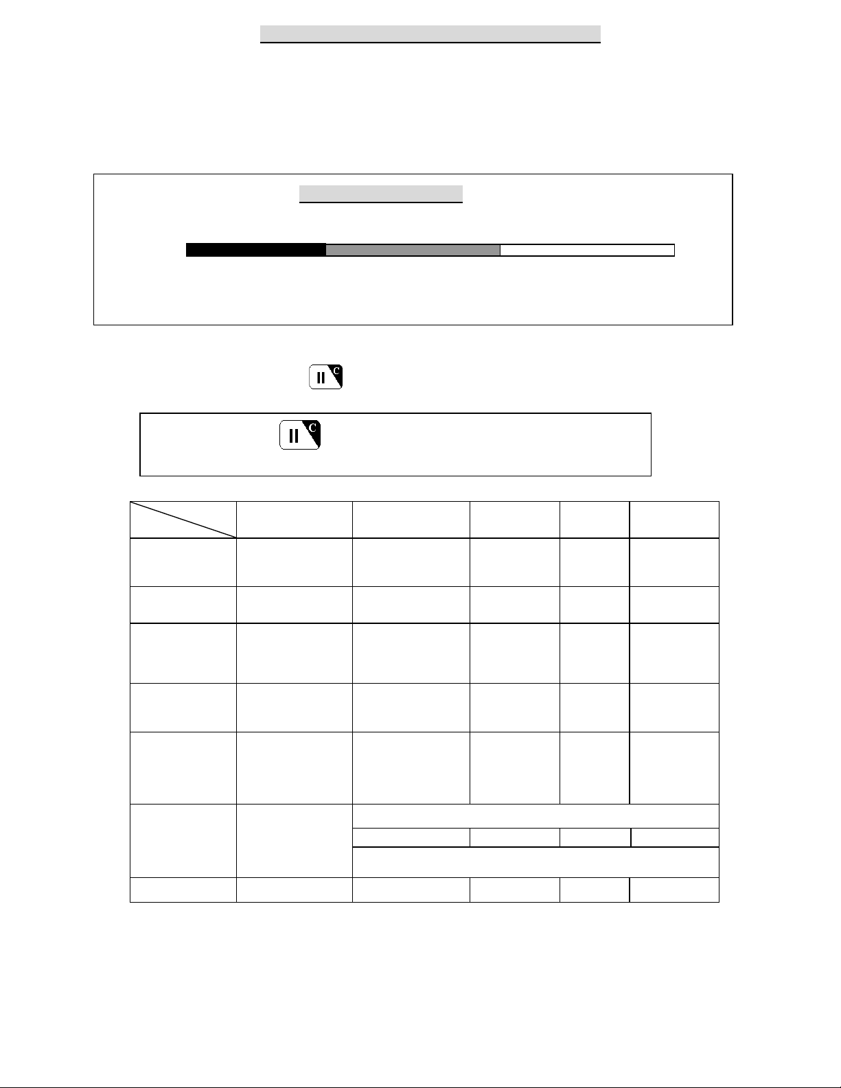
REACTION OF LS-30 TO DIFFERENT ALARMS
The response of the LS-30 to various alarms and abnormalities is shown below. Burglar alarms can only be
issued when the system is in AWAY or HOME mode, while Fire, Panic, Medical and Special alarms can be
triggered anytime, regardless of the system operation mode. When any of these alarms occur, the LS-30 will
dial the correct phone numbers to call for help.
Burglar Alarm Response
AWAY Mode Entry Delay Burglar Alarm →
System status:
↑ (0-255 seconds) ↑
Burglar sensor triggered Siren goes off, dialing---
If necessary, you can interrupt dialing and stop the siren by disarming the system, and clear the alarm
LED/LCD by pressing (Hot Key)
Press (Hot Key) : stop siren, stop dialing, clear LED/LCD status.
Sources &
Alarm
Burglar
Fire Smoke Detector
Responses
Panic Panic button of
Medical Wireless Medical Button
Trigger Sources Dialing Tel. Numbers
PIR
Door Magnet
Glass Break Detector
Vibration Sensor
Gas Detector
CO Detector
Remote Controller
Wireless Keypad
Emergency buttons on
Base Unit
Inactivity
Special Temperature Sensor
Sensor Tampered
Humidity Sensor
Flood Detector
Light Detector
Analog Sensor
Power Meter
All sensors
Sensor Trouble or Low
Battery
All sensors None None Silent OFF
Besides CMS
Pager+ Burglar+ Common
1-4+
Pager+ Fire+ Common
1-4+
Pager+ Panic+ Common
1-4+
Pager+ Medical+Common
1-4+
Pager+ Special+ Common
1-4+
None
Voice message
on telephone
Burglar+ Common
Fire+ Common
Panic+ Common
Medical+ Common
Special+ Common
(Disarm State)
None
(Arm State)
Same As Burglar Alarm
Voice on
Base Unit
Silent
Fire Message
Programmable
Silent
Medical
Message
Programmable
Special
Message
Programmable
Silent Programmable
Siren Status
Programmable,
Programmable,
Programmable,
* Siren off
Programmable,
Programmable
16
Page 19

ANSWERING CALLS FROM THE LS-30
When you receive a call from the LS-30, you can follow the procedures below to communicate with the
system.
When you pick up the phone, your voice on the line will trigger the appropriate message from the LS-30
(For the telephone number assigned as voice acknowledgement).
You will hear the prerecorded message twice, telling you what event happened to the system.
After the announcement, the LS-30 enters into monitoring and 2-way communication mode for 60
seconds. You can hear any sound picked up by the microphone on the Base Unit or talk to the people
inside the house. During these 60 seconds, you can also control your LS-30 through the telephone
keypad.
If you don’t press any key during this period, the first 30 seconds will be listen-only and then -after two
beeps- the system will enter into 2-way hands-free speaker phone automatically. Ten (10) seconds before
the termination of the telephone connection, one beep will be delivered to remind the user.
Press 0 : LS-30 disconnects immediately; stop any further dialing; stop siren.
Press 1 : LS-30 disconnects immediately and dials the next number, stop siren.
Press 3 : Enter into speak-only mode. (The microphone on the LS-30 is disabled.)
Press 5 : Enter into 2-way hands-free speaker phone.
Press 8 : Enter into listen-only monitoring.
Press any other key: LS-30 will extend the connection for another 60 seconds.
The sound of the siren or noise from the environment may interrupt the decoding of the input key tone,
so keep pressing the key until the command becomes effective.
If this telephone number needs a DTMF tone acknowledgment, remember to press a key (any key) on the
telephone keypad in the answering process to prevent LS-30 from redialing this number later.
Answering Sequence
LS-30 Voice
Dialing Announcement 60 sec. Monitoring &
Twice 2-way Communication
Ring!---Ring!
0 : LS-30 disconnects, stops further dialing & stops the siren.
1 : LS-30 disconnects and dial next number.
3 : Enter into speak-only mode.
5 : Enter into 2-way hands free speaker phone.
8 : Enter into listen-only monitoring.
: If any other DTMF key is pressed, the connection is
extended for another 60 seconds.
Answered by
voice (“hello”)
or by pressing
a DTMF key
Only accept
Commands
5 and 8
17
Page 20

DIAL-IN CONTROL
User can control and check with your LS-30 from a phone anywhere in the world by enabling the
auto-answer function (refer to (4-2) Set Telephone – Set Auto Answer) and set the ring count number.
Notes: 1. If you connect a fax machine or auto-answering machine on the same telephone line, you might
need to refer to their manuals and Appendix A-7 to avoid any disoperation.
2. The ring count number is only effective for the dial-in from PSTN (land line) and it should be
over three rings; otherwise, the noise on the phone line may trigger the dial-in control process.
3. The pulse-dialing phone set can’t dial in to control the system.
The operation of dial-in control is as follows:
1. Dial the telephone number to which LS-30 is connected.
2. After the preset ring count number (for land line), you will hear beeps.
3. Key in the user password (preceded by * and followed by # ) from the telephone keypad within 30
seconds. If the system recognizes the password you will hear beeps, otherwise you should enter again.
4. After the password has been recognized, the LS-30 will enter into monitoring mode for 30 seconds and
then -after two beeps- the system will enter into 2-way hands-free speaker phone automatically. Ten (10)
seconds before the termination of the telephone connection, one beep will be delivered to remind the user.
5. During the 60 seconds, you can also enter commands from the telephone keypad to control the LS-30.
* 0 : Disarm the LS-30 after you exit Dial-in Control (echoed by voice).
* 1 : Arm the LS-30 in Home Mode after you exit Dial-in Control (echoed by voice).
* 2 : Arm the LS-30 in Away Mode after you exit Dial-in Control (echoed by voice).
* 3 : Enter into speak-only mode (echoed by “OK”).
* 4 : Check alarm event and operation mode (echoed by voice).
* 5 : Enter 2-way hands-free speaker phone (echoed by “OK”).
* 6 x x 1 : Turn on the switch number x x (xx = 01-15) (echoed by “OK”).
* 6 x x 0 : Turn off the switch number x x (xx = 01-15) (echoed by “OK”).
* 7 1 : Turn on the Relay (echoed by “OK”).
* 7 0 : Turn off the Relay (echoed by “OK”).
* 8 : Enter into listen-only monitoring (echoed by “OK”).
* 9 : Disconnect the line immediately.
Any other keys will extend the monitoring period for another 60 seconds (echoed by beeps).
The Process of Dial-in Control
Dial Phone Number Enter Password 60 sec. Monitoring &
Ring count as preset within 30 seconds 2-way Communication
----------- *xx--xx# Ready for key tone command
Ring Ring
18
Page 21

INSTALLER & CMS SETTINGS
19
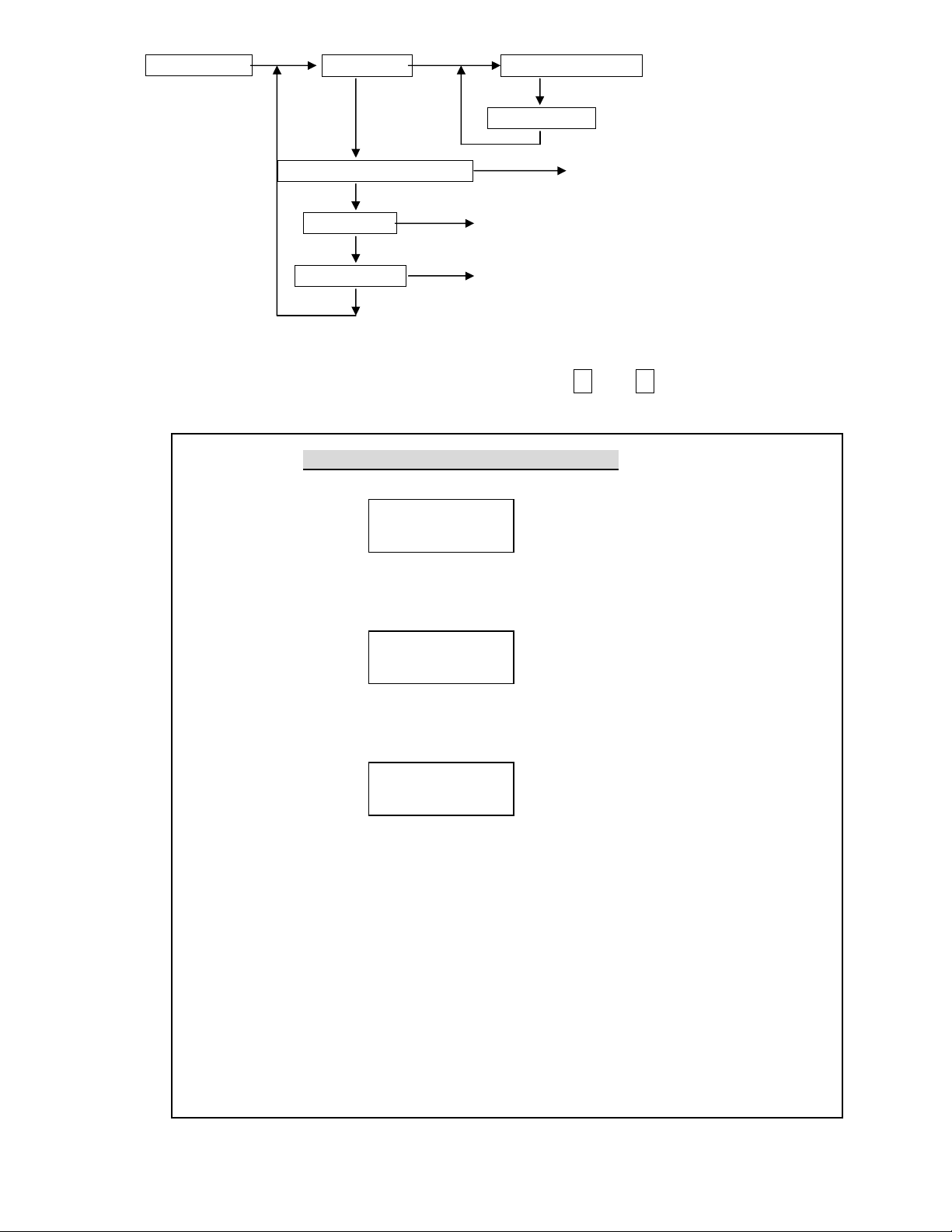
Page 22

The Installer Mode is for the installer to set up the system.
Enter Installer Password
(4) Installer Mode Set Timer (4-1)
Set Telephone (4-2)
Set Sound (4-3)
Set Device (4-4)
Set Siren (4-5)
Set Misc. (4-6)
(4-1) Set Timer Set Entry Delay
Set Exit Delay
Set Inner Siren Time
Set Relay Action Time
Set Sensor Supervise Time Unit In Second
Set Remote Siren Time Unit In Minute
20
Page 23

Entry Delay for Burglar Sensors: (0-255 seconds, default=0 sec.)
This setting is the time between any burglar sensor triggers and the alarm reaction procedure starts.
When you return home and open the door, the Base Unit will issue warning beeps (if the Entry
Delay Beep = On) to remind you that the system is still in the Arm state and you should disarm the
system within this time. (Refer to the (4-3) Set Sound - Entry Delay Beep.)
AWAY Mode Entry Delay Burglar Alarm →
System status:
↑ (0-255 seconds) ↑
Burglar sensor triggered Siren goes off, dialing---
This Delay only works on the Burglar Sensor with its Delay ON/OFF setting in ON state.
(Refer to (4-4-1) Change Device Setting - Burglar Sensor - Enable State - Delay ON/OFF.)
For the system controlled by Wireless Keypad, this timer should be set more than 20 seconds.
Exit Delay for Controllers: (0-255 seconds, default=0 sec.)
This setting is the time between selecting the AWAY mode and when the AWAY arm
becomes effective. During this time, the Base Unit will issue warning beeps to remind the
people still in the house to leave as soon as possible.
Since the Door Open signal may last for 10 seconds, so add 10 seconds to the time you need to
leave the house as the Exit Delay. (Ex. you need 20 seconds to leave the house, set Exit Delay=30s)
Disarm Exit Delay AWAY ARM effective →
System status:
↑ (0-255 seconds)
Set AWAY mode
This Delay only works on the Controller with its Delay ON/OFF setting in ON state.
(Refer to (4-4-1) Change Device Setting-Controller-Enable State-Delay ON/OFF)
For the system controlled by Wireless Keypad, this timer should be set more than 20 seconds.
Inner Siren Time: 0-255 seconds (default, 60 sec.)
The time of the Inner Siren sounds when an alarm trips and Inner Siren is enabled.
(Refer to (4-5) Set Siren-Set Inner Siren.)
Relay Action Time: 0 second to 120 minutes (default, 60 sec.)
The activation time of the Alarm Relay output (on the rear panel) when the alarm trips.
Sensor Supervise Time: 0-24 Hours (default, 12 Hours)
The LS-30 is a supervised RF wireless system, meaning supervised sensors send “heartbeat” RF
signals to the Base Unit at a certain time interval. If the Base Unit does not receive the RF check
signal from a supervised sensor within the Sensor Supervise Time, the LS-30 considers this
sensor to be missing and issues a warning message.
This time can be set from 0 to 24 hours (0 hour means that the system will not check the “heartbeat”
signal.
Please note, the time shorter than 4 hours would increase sensor “RF Loss” possibility.
Remote Siren Time: 0 seconds to 30 minutes (default, 60 sec.)
The time of the wireless Remote Siren sounds when the alarm trips. (The Remote Siren is an
Option.)
21
Page 24

(4-2) Set Telephone Set Telephone Number (4-2-1)
Set Dial Mode Tone
Pulse 33/66
Pulse 40/60
Set Auto Answer Auto Answer On Set Ring Count
Auto Answer Off
Set Telephone Line Cut Detection Permanent Off
Away Mode On
Permanent On
Set Cease Dialing Mode 30 Minutes Due
CMS Report OK
Set Tel. Ringer Tel. Ringer On/ Off
Set Dial Tone Check Dial Tone Check Enable/ Disable
Dial Mode: Tone /Pulse 33/66 /Pulse 40/60 (default, Tone)
Check your telephone system and select the proper Tone or Pulse mode for the auto-dialer.
Auto Answer Ring Count: Auto Answer ON with Ring Count 1-30 /Auto Answer OFF
(default, Auto Answer OFF)
Auto-Answer ON: The Base Unit will answer the incoming call automatically after the ring count
number set in this command has been reached. (You have to switch on this function, if you want
to use dial-in control. Three or more ring counts are recommended to avoid triggering by
noise.)
Auto Answer OFF: The Base Unit will not answer the incoming call.
22
Page 25

Telephone Line Cut Detection: Permanent OFF /Away Mode ON /Permanent ON
(default, Permanent OFF)
The LS-30 checks the telephone line voltage and if the line voltage is abnormal, the siren will go off
(the Inner Siren should be switched on) to alert the user. (refer to (4-5) Set Siren - Inner Siren.)
Permanent OFF: Never check the telephone line state.
Away Mode ON: Check the telephone line state only in AWAY mode.
Permanent ON: Always check the telephone line state.
Note: To implement this function the telephone line must not connect any auto answering devices
like FAX machine or TAM (Telephone Answer Machine).
Cease Dialing Mode: 30 Minutes /CMS Report OK (default, 30 Minutes)
30 Minutes: The auto-dialer stops dialing after 30 minutes or after all the telephone numbers
have been dialed 5 times without a successful connection.
CMS Report OK: The auto-dialer stops dialing after the report to CMS is successful.
The Latchkey number still will be dialed when the Latchkey Controller Arms/Disarms the system
or the detection of Power Loss/Restore event, even this status is set as “CMS Report OK”.
Tel. Ring: ON/OFF (default, OFF)
Tel. Ring ON: Sound the ringer for incoming calls.
Tel. Ring OFF: Ringer deactivated for incoming calls.
Dial Tone Check: Enable/Disable (default, Enable)
Dial Tone Check Enable: The auto-dialer checks for a dial tone before dialing.
Dial Tone Check Disable: The auto-dialer will not check for a dial tone and dials immediately.
23
Page 26
(4-2-1) Set Telephone Number Common 1 Number
24
Common 2 Number
Common 3 Number
Common 4 Number
Panic Number Answer By Voice
Burglar Number Answer By Tone
Fire Number
Medical Number
Special Number
Latchkey/(power) Number
Pager Number
Pager Data
As many as 10 telephone numbers and one pager number can be set in the auto-dialer, each up to 23 digits.
4 common numbers and pager number:
These will be dialed in all types of alarm. They can be the numbers of your office, friends, neighbors
or family members.
5 specific numbers each for different alarms:
These will be dialed only when the LS-30 is triggered by the specified alarm. For example, the fire
number will be dialed only in a fire alarm.
Latchkey number /Power status report number:
This number will be dialed, disregard the Cease Dialing Mode Setting (refer to (4-2) Set Telephone-
Set Cease Dialing Mode), if following things happen:
1). When a Latchkey Remote Controller (Refer to (4-4-1) Change Device Setting- Enable State-
Latchkey) or a user with the Latchkey password (User 9 or User 10 password) leave the house
(change from Disarm/ Home Mode to Away Mode) or enter into the house (change from Away
Mode to Disarm/ Home Mode).
This function is useful to parents who want to make sure their children have returned home safely.
Usually, the Latchkey number will be the parents’ mobile phone number.
Note: This function is not applicable for Partial Zone 91-99.
Page 27

2). When the Base Unit detects AC power break or restore, this number will be dialed after a random
delay of 60-120 seconds, The pre-recorded messages (power loss/power restore) will be played when the
call is successfully connected.
Pause Insertion
Note: Use the Pause key to insert pauses between telephone number digits for dialing
to/from a PABX extension number. Each pause is equivalent to a 3-second break.
Answering status: Voice /Tone (default, Voice).
After dialing, the LS-30 needs an acknowledgement from the called party, either by voice
like “Hello” or by a DTMF key tone to ensure the call is connected successfully. With no
acknowledgement, the call will be deemed to be failed and will be redialed in the next loop.
Dialing Sequence for Alarm Report
CMS1 Number →→→→ CMS2 Number →→→→ Pager →→→→ Specific alarm number →→→→ 1st to 4th
Common numbers
If there is any number that cannot be connected successfully, the auto-dialer will skip to the
next one and try again in the next loop until all the numbers have been tried 5 times or the
cease dialing condition has been reached. (refer to (4-2) Set Telephone - Set Cease Dialing
Mode.)
Note: 1, CMS1 and CMS2 are Central Monitoring Station numbers (refer to the (5) CMS Mode).
2, If Ethernet Report has been set (refer to (5) CMS Mode-Set CMS1-Ethernet
Report) the alarm report will be sent to Internet CMS Server first before any alarm
report through PSTN.
25
Page 28

(4-3) Set Sound Record Voice Common Segment 13 Second Record
Panic Segment 4 Second Record
Burglar Segment 4 Second Record
Fire Segment 4 Second Record
Medical Segment 4 Second Record
Special Segment 4 Second Record
Latchkey Disarm 4 Second Record
Latchkey Away 4 Second Record
Voice Check (Same as 2-2)
Set Entry Delay Sound Beep Away Mode Off
Alarm Warning Alarm Warning On/ Off
Record Voice: After an alarm call connects successfully, the LS-30 will play the prerecorded voice message
that corresponds to the alarm type.
The messages should be recorded in their specified segments.
Common Segment (13 seconds): The voice to be played during all alarm types. This segment should
contain your name, address and telephone number.
Ex: “This is ---, I live at---, phone number is---.”
Panic Segment (4 seconds): The voice to be played during a Panic alarm.
Ex: “Break-in! Break-in! Calling for emergency help.”
Burglar Segment (4 seconds): The voice to be played during a Burglar alarm.
Ex: “Burglar! Burglar! Calling for emergency help.”
Fire Segment (4 seconds): The voice to be played during a Fire alarm.
Ex: “Fire! Fire! Calling for emergency help.”
Medical Segment (4 seconds): The voice to be played during a Medical alarm.
Ex: “Heart patient! Calling for emergency help.”
Special Segment (4 seconds): The voice to be played during a Special alarm.
Ex: “High temperature in the building! Calling for an alert.”
Latchkey Disarm (4 seconds): The voice to be played when a latchkey user disarms the system.
Ex: “I’m home.”
Latchkey Away (4 seconds): The voice to be played when a latchkey user sets the system in AWAY mode.
Ex: “I’m out.”
26
Page 29

27
Entry Delay Sound: Beep/ Away Mode /OFF (default, OFF )
Beep : The Base Unit will generate beeps during the Entry Delay interval and the beeping speed will
get faster until the end of the delay time. (Refer to (4-1) Set Timer-Entry Delay)
Away Mode Voice : The Base Unit will generate the voice of “Away Mode” during the Entry Delay
interval until the end of the delay time. (Refer to (4-1) Set Timer-Entry Delay)
OFF: No beeps during the Entry Delay interval.
*Alarm Warning: ON/OFF (default, OFF)
Alarm Warning ON: The Base Unit generates “Dong” sound in every 5 minutes if there is any
pending alarm status (RED LED constantly on) on the panel.
Alarm Warning OFF: No “Dong” sound even with pending alarm in Disarm Mode.
Page 30

(4-4) Set Device Enroll Device Controller Enroll
28
Burglar Sensor Enroll
Fire Sensor Enroll Zone Number
Medical Button Enroll
Special Sensor Enroll
Change Device Setting (4-4-1)
Delete Device Controller Delete
Burglar Sensor Delete
Fire Sensor Delete Zone Number
Medical Button Delete
Special Sensor Delete
Special Sensor Limit Set Enter Zone Number High/Low Limit
Wire Sensor Assignment Select Input Select Type (4-4-1) Enable State
Enroll Device: The LS-30 uses smart code technology. The Base Unit identifies its sensors by their unique
IDs, so the Base Unit has to learn all the sensors’ ID code in the initial system setup. (Each sensor has
a unique ID that is preset at the factory.)
60 seconds for Device Enroll
After initiating the Enroll Device procedure, there is a 60-second time window for the
device to transmit a RF signal to complete the code learning.
Delete Device: Remove the device from the system.
Special Sensor Limit Set: Set High/Low trigger limits for Special sensors like temperature sensor and
humidity sensor. Please refer to the special sensor’s user guide.
Wire Sensor Assignment: Set the parameters for the wire sensor inputs from the rear panel.
Up to three wire sensors can be assigned.
(The wire sensor input can be selected as a close or open trigger.
The Zone numbers of the wire sensors are fixed to “00-01=Aux1”, “00-02=Aux2”,
“00-03=Sensor In”.)
Page 31
(4-4-1) Change Device Setting Controller Change
29
Burglar Sensor Change Enter Zone Number
Fire Sensor Change Enable State
Medical Button Change Zone Number
Special Sensor Change Switch Control
Enable state of devices:
Device On Duty/Bypass (default, On Duty): (For all devices)
Device On Duty: This sensor is working in the system currently.
Device Bypass: Bypass this sensor; the system will ignore the alarm signal received from this sensor.
Delay ON/OFF (default, Delay=OFF): (For Controller & Burglar sensor)
Delay ON: (Refer to (4-1) Set Timer - Exit Delay/Entry Delay.)
For the Remote Controller, the Exit Delay time will be imposed on the Away command from
this controller.
For the Burglar sensor, the Entry Delay time will be imposed on the Burglar alarm signal from
this sensor.
Delay OFF: The trigger signal or command from this sensor or controller will be processed
immediately, regardless of the Exit/Entry Delay setting in (4-1).
24-Hour Zone YES/NO (default, 24-Hour Zone= NO): (For Burglar sensor)
24-Hour Zone/YES: This Burglar sensor’s trigger signal will be processed all the time regardless of
the system’s operation mode, either in Arm or Disarm.
24-Hour Zone/NO: This sensor’s trigger signal will only be processed in Arm Mode.
Home Mode Active/Inactive (PIR default= Inactive, Magnet default= Active): (For Burglar sensor)
Home Mode Active: This Burglar sensor will trigger an alarm in Home Mode operation.
Home Mode Inactive: This Burglar sensor will not trigger an alarm in Home Mode operation, it
will only trigger an alarm in Away Mode operation.
Pre-warning ON/OFF (default, Pre-warning OFF): (For Burglar Sensor)
Pre-warning ON: When this device is triggered in Arm condition, it only turns on the corresponding
switches those set by this device for 30 seconds to warn the person who approaching the
protected area. (If 24-Hour Zone set, the switches will turn on anytime when this device is
triggered.). It won’t trigger burglar alarm.
Voice Warn ON/OFF (default, Voice Warn ON): (For Fire, Medical and Special alarm sensors)
Voice Warn ON: If this sensor triggers an alarm, there will be a 30-second voice warning from the
Base Unit before the alarm reaction procedure starts.
Voice Warn OFF: There is no voice warning. The Base Unit responds immediately when there is an
alarm triggered by this device.
Siren/Relay ON/OFF (default, Siren/Relay ON, only OFF for Controller): (For all devices)
Siren/Relay ON: The Relay will act and sirens (both Inner Siren and Remote Siren) will go off
when there is an alarm triggered by this sensor after the Delay time or Voice Warning passes.
Siren/Relay OFF: The Relay will not act and sirens will keep silent when there is an alarm triggered
Page 32

by this device.
30
Bell ON/OFF (default, Bell OFF): (For Burglar sensor)
Bell ON: In Disarm Mode, the Base Unit will issue a doorbell chime when receiving a trigger
signal from this sensor if the Bell status is set to ON in Master Mode (refer to (3) Master
Mode - Bell Check - Door Bell.)
Bell OFF: Doorbell chime will not sound when receiving a trigger signal from this sensor.
Suggestion: This state should be switched on for the Door Magnet sensors on the front and back doors.
Latchkey ON/OFF (default, Latchkey= OFF):
(For Remote Controller, Not for the Controllers assigned in Group number 91-99 Partial Arm Zones)
Latchkey ON: This Remote Controller is assigned as a Latchkey Remote Controller. (refer to
(4-2-1) Set Telephone Number - Latchkey Number.)
Latchkey OFF: No latchkey number will be dialed for this controller.
Inactivity ON/OFF (default, Inactivity=OFF): (For Burglar Sensor)
Inactivity ON: This Burglar Sensor is assigned as an Inactivity Sensor (no longer be a Burglar
Sensor or Pre-warning Sensor) to monitor the activity of an elderly or physically challenged
person in the protected area. If no activity has been detected during the preset Inactivity Time
(refer to (4-6) Set Misc.-Set Inactivity) an Inactivity Alarm (medical) will be issued.
Inactivity OFF: This is a normal Burglar Sensor.
Supervision ON/OFF: (Automatically set by the sensor itself)
(Refer to (4-1) Set Timer - Sensor Supervise Time.)
Supervision ON: System will check the “heartbeat” signal from this sensor.
Supervision OFF: System will not check the “heartbeat” signal from this sensor.
Type Alarm/Control (default, Type=Alarm): (For Special Sensors)
To assign the Special Sensor as an Alarm Device or a Control Device.
(refer to the manual of the Special Sensor.)
Operation Low/High (default, Operation=Low): (For Special Sensor)
To activate the switches or the Relays when the reading reaches the low limit or high limit for
the sensor that is set in Control Type. (refer to the manual of the Special Sensor.)
Switch control: Select the switches that will be activated when this sensor is triggered.
Note: Switch #16 is not allowed for this purpose as this switch has been assigned as the indicator
of the Arm/ Disarm Status. (refer to (4-6) Set Misc.- Set SW # 16.)
X-10 Switch
As many as 15 switches (switch #16 is for Operation Mode indication, refer to (4.6)) can be controlled
by each system. For settings of the X-10 switches, refer to the instructions of the X-10 device manual.
Note: For a Remote Controller, if you press the DISARM button in DISARM Mode, the switches that
have been assigned as active switches will be turned ON or OFF alternatively.
Entry Delay ON/OFF (default, Entry Delay=OFF): (For Wire Sensor input only)
The Entry Delay time (refer to 4-1) should be imposed on the trigger of this input or not.
Trigger Close/Open (default, Trigger=Close): (For Wire Sensor input only)
Alarm will be triggered by close (grounding) or open (>3V) the sensor input contact (or voltage).
*Away Close/Open (default, Away=Close): (For Wire Sensor input assigned as a Controller only)
System will enter Away or Disarm Mode by close (grounding) or open (>3V) the sensor input
contact (or voltage).
Page 33

(4-5) Set Siren Set Inner Siren Inner Siren On/OFF
31
Set Mode Change Chirp Mode Chirp On/OFF
Set Tamper Siren In Disarm Siren On/OFF
Siren/Relay Test Start Test
Inner Siren: ON/OFF (default, ON)
Inner Siren On: Enable the Inner Siren.
Inner Siren Off: Switch off the Inner Siren. (The Siren keeps silent in alarm and warning states.)
The conditions for the Inner Siren to go off when alarm trips:
1. The Inner Siren is enabled.
2. The Siren/Relay ON/OFF attribute of the sensor is in the ON state. (refer to (4-4-1) Change Device
Setting-Siren/Relay ON/OFF.)
3. The Inner Siren Time has been set. (refer to (4-1) Set Timer-Inner Siren Time)
Mode Change Chirp: ON/OFF (default, OFF)
Mode Change Chirp On: The Sirens sound short chirps (Disregard the Inner Siren status) when the
operation mode changes by Remote Controller or Wireless Keypad. (Disarm: 1 chirp, Away: 2
chirps, Door Open warning: 5 chirps).
Mode Change Chirp Off: The Sirens will keep silent when the operation mode changes.
Tamper Siren In Disarm: ON/OFF (default, OFF)
Tamper Switch
There is a Tamper Switch in the Base Unit (please refer to Attach the Base Unit to the wall using the
Mounting Bracket). This switch will be closed by the Tamper Switch Cam when the Base Unit is
attached to the Mounting Bracket. If someone detaches the Base Unit from the Mounting Bracket, the
Tamper Switch will be triggered.
Also refer to the specific sensors’ descriptions for more about their tamper function.
Tamper Siren In Disarm On: The Siren will go off for 10 seconds, (the Inner Siren has been enabled)
if someone detaches the Base Unit from the Mounting Bracket or triggers the Tamper Switch (on
Base Unit or sensors) in Disarm Mode.
Tamper Siren In Disarm Off: The siren will not go off when receiving the tamper signal from
sensors or from the Base Unit in Disarm Mode.
Siren/Relay Test: This test will activate the Inner Siren, close the Relay contacts and send an
Activate signal to the Remote Siren (if a remote siren is installed) immediately regardless
of the Inner Siren state.
Page 34

32
(4-6) Set Misc. Set RF Jamming Warning
Check ROM Version
Reset To Factory Default Enter to Reconfirm
Emergency Button Assignment
Set Inactivity Inactivity ON Inactivity Time
Set Password Inactivity OFF
Set Modem Ring Count= 1~30
Set SW #16 Arm/Disarm =ON
RF Jamming Warning: (default, OFF) Enable or disable the RF jamming warning.
Reset To Factory Default:
All the settings in the Base Unit will be returned to factory default except recorded voice and
telephone numbers.
Emergency Button Assignment: Panic /Medical (default, Panic)
Select the function of the Emergency Button as a Panic Button or a Medical Button (The zone
number of this button is 00-05.).
Set Inactivity: ON /OFF (default, OFF)
Inactivity On with time (0-72 hours):
1, Treats the Inactivity signal from the Wireless Medical Button as a Medical Alarm.
(The Medical Button will send Inactivity signal if no activity has been detected in 12 hours.)
2, If no activity has been detected during this time from any Inactivity Sensor (Refer to (4-4-1)
Change Device Setting-Burglar Sensor-Enable State-Inactivity) the system will issue the
Inactivity Medical Alarm (with zone number of 00-06).
Inactivity Off: Ignore the Inactivity signal from the Wireless Medical Button and don’t check
the Inactivity Timer.
Set Password: (default, “1234”) Edit the Installer Password.
Set Modem–Ring Count (1-30): (default, Ring Count=3)
This setting is only valid for the system equipped with an optional Data Communication Module.
After this ring count number the Module will connect (off hook) to the telephone line automatically.
Note: After this ring count has been set, user should connect the Module to the system then enter
Master Mode and press Hotkey “C” (clear status) to pass this parameter to the Module.
Set SW #16: (default, ARM ON): Set the #16 switch as an Arm/Disarm status indicator.
Arm On: The #16 switch will be turned on in Away and Home Mode.
Disarm On: The #16 switch will be turned on in Disarm and Monitor Mode.
Page 35

(5) CMS Mode Set CMS1
33
Set Mode Change Report Report On/ Off
Set CMS2
Auto Link Check Auto Link Check On Check Interval
Loopbcak Test Auto Link Check Off
Set 2 Way Audio 2 Way Audio ON/OFF
Set DTMF Data Time DTMF Data=50ms /100ms
Set Telephone Number Telephone Number
Account Number
Set Password CMSx Number
(CMS1 only)
Set CMS Report Report All/ One
Ethernet Report (CMS1 only)
Mode Change Report: ON /OFF (default=OFF, For PSTN)
Mode Change Report On: The LS-30 will report to the CMS if the operation mode
(Away/Home/Disarm) has been changed.
Auto Link Check: ON/OFF (default=OFF, For PSTN)
Auto Link Check On: The LS-30 will send a check signal to the CMS periodically.
Loopback Test: (For PSTN) The LS-30 will send a link check signal to the CMS immediately.
2 Way Audio: ON/OFF (default=OFF, For PSTN)
2 Way Audio ON: The Base Unit will enter into 2-way voice communication mode after sending the
alarm report to the CMS.
(This function only works with a digital receiver using Contact ID and has 2-way voice capability.)
DTMF Data Time: 50ms/100ms for PSTN report (default=50ms, For PSTN)
Select the DTMF data pulse time as 50ms or 100ms for the Contact ID protocol.
(Please consult with your CMS provider if you want to change this parameter.)
Telephone number & account number:
*The PSTN (land line) CMS telephone number (16 digits Max.).
*The user account (8 digits Max.). The CMS1 account number is also used for IP Alarm Report
Password: The CMS password to access the LS-30 Base Unit.
CMS Report: (default, Report ALL)
Report All: Report to CMS1, CMS2 and Internet service centers.
Report One: Stop further CMS report if any one of the above reports is successful.
Ethernet Report: YES/NO (default NO), only for the system equipped with Ethernet/wifi/GPRS Adaptor.
Alarm message will be reported to the CMS server through the Internet.
Page 36

34
SPECIFICATIONS
Base Unit
Input Power: 15VDC/800mA regulated.
Standby Current: 50mA.
RF : (Follows local regulations, other frequencies as requested)
Frequency: 915Mhz receiver, 433Mhz transmitter
Data Modulation: OOK.
Power: less than 10mW.
Range: about 100m to 300m @open field, 25℃ (Depends on sensors).
Receiver Type: super heterodyne.
RF Security Code: 16,777,216 combinations with check sum for each type of sensors.
More than 4 billion combinations in total.
Communication Link: Standard PSTN (land line), Optional Ethernet
Telephone Dialing: Pulse/Tone selectable.
Preset Telephone Number: 10 phone numbers, one pager, 2 CMS data links
Voice Recording: 120 seconds in total.
Emergency announcement in 6 segments, 13 seconds for common segment, 4 seconds
each for Panic, Burglar, Fire, Medical, Special and Latchkey/ Power segments.
Event Log: max. 512 records.
Display: 3 LEDs, 2x16 LCD panel with blue color backlight.
Sensor Zones: total 288 zones. (Burglar zones x 128, Fire zones x 64, Controller zones x 32,
Medical zones x 32, Special sensor zones x 32)
Memory Back-up Time: Min. 3 months after power break.
Battery Back Up Operation Time: about 15-26 hours standby. (depends on back up battery type, only for the
operation of the Base Unit)
Password: 14 passwords each with max. 8 digits.
3 Wire Sensor Inputs: Each can be assigned as Panic, Burglar, Fire, Medical, Tamper or Controller.
Alarm Out: 230V AC /5A rate relay contacts or DC output selectable.
Delay Activation Time: 0- 255 seconds programmable.
Digital Interfaces COM1(RJ9): UART (0-5V, 9600/ 8 bits/no parity/1stop bit)
For RS-232 Adaptor, USB Adaptor or Ethernet Adaptor..
Digital Interface COM2(RJ45): (for switch control interface)
Switch control: Control of 16 units X-10 switches or (XRM-01) Relay Modules. I2C Adaptor
(optional)
Remote Display Memory: 30 characters/set, total 10 sets.
Internal Siren: 110dB at 30cm distance.
CMS protocol: Contact ID with
Clock Accuracy: within 5 seconds daily.
Telephone Line Cut Detection Voltage: 20V+/- 4V. (this function may not be used in some countries.)
Operation Temp.: -10℃~50℃.
Storage Temp.: -20℃~60℃.
Humidity: 10-95%RH.
Size: 248x180x52 mm.
Weight: about 950 g.
Note: External GSM is an option for European market, LS-30 don’t use wi-fi, only wire Ethernet interface.
(The manufacturer reserves the right to change the specifications without prior notice)
Page 37

APPENDIX
ToCOM1
Power Line
COM2
35
Data communication Module
Ethernet Adap
tor connect to Internet
Ethernet
/wifi/GPRS
Adaptor or
A-1. In-coming Message Display.
A user or a CMS can send messages to the LS-30 if the Base Unit has been connected to the Internet
through the Ethernet Adaptor (optional) by using the HyperSecureLink program.
The LCD display will show “Messages Come In” and issue a warning sound periodically to remind
the user if any new message has been received by the LS-30 Base Unit. The user can check the
message by pressing (Hot Key) 5 after the password has been entered in Disarm Mode.
Up to ten 30-character messages with time tag can be stored in the memory of the Base Unit. Stop the
warning sound by pressing (Hot Key) C after entering the password.
(Note: ! and & are not allowed in the message)
A-2. Connection Diagram for USB or RS-232 Computer Interface
To PC
To LS-30
COM1
USB or COM Port
COM1 cable USB or RS-232 Adaptor HyperSecureLink Software
(Note: For the USB Adaptor driver, please refer to the USB-3 Installation Guide in the CD ROM.)
A-3. Connection Diagram for the Ethernet Adaptor or the Data Communication Module
connects to Telephone network
Internet
Or PSTN
Router
COM1 Cable
Data Communication Module
HyperSecureLink or
CMS polling software
A-4. Connection Diagram for the X-10 Power Line Interface
.
To LS-30
X-10 Appliance Module X-10 power Line Interface Controller X-10 or COM2 Cable
Page 38

A-5. Terminal Board Connection
36
Wire Siren
Wire
Sensor 3
Arm LED
Indicator
Wire
Sensor 2
Wire
Sensor 1
+12V DC: This terminal provides +12V~15V/300mA output for the customers to connect their own devices.
(Note: The output voltage depends on the power adaptor and will be shut down if the external
power fails.)
ALARM OUT: These two terminals are the Alarm Relay Outputs. These two terminals can be selected as
dry contacts or 9V~15V/GND output, depending on the setting of the ALARM OUT
SELECTOR.
SENSOR INPUT: There are three terminals: AUX 1 (Wire Sensor 1), AUX 2 (Wire Sensor 2) and
SENSOR IN (Wire Sensor 3), can accept NO/NC type alarm sensor input. Refer to (4-4)
Set Device-Wire Sensor Assignment for the settings of these three sensor inputs.
AUX OUT 2: This output represents the status of system operation mode. In the ARM mode (AWAY &
HOME) this output will send out +5V voltage (protected by a serial 2k ohms resistor) to
this terminal. The user can connect a LED display for ARM state indication purposes.
A-6. Using the same telephone line to connect the LS-30, Fax machine and Telephone Answering
Machine (TAM)
Telephone Line
The LS-30 Base Unit, a Fax Machine and a TAM can be connected to the same telephone line and all
these devices will still be able to accept their own dial-in control signal.
1. The auto answering ring counts (Refer to (4-2) Set Telephone-Set Auto Answer for LS-30) should
be set as:
LS-30 ring count> Fax ring count >TAM ring count.
Page 39

—Reorient or relocate the receiving antenna.
—Increase the separation between the equipment and receiver.
—Connect the equipment into an outlet on a circuit different from that to which the receiver is
connected.
—Consult the dealer or an experienced radio/TV technician for help.
Ex. If the ring count of the LS-30 is 8, the ring count of the Fax should be 6 and ring count of
TAM should be 4.
2. Set the operation mode of the Fax machine in TAM mode. (Please refer to the manual of the Fax
machine.)
3. When you dial in, the TAM will connect first.
If you want to record a message on the TAM, just do it.
If you want to send a Fax, just press the send button on the Fax machine.
If you want to control the LS-30 system, after the announcement from the TAM is over (or the
Fax tone from the Fax machine is over) then key in the password, and the LS-30 will take control
of the telephone line.
Note: 1, The Line Cut Detection function should be disabled (Refer to (4-2) Set Telephone-Set
Telephone Line Cut Detection-Permanent Off), otherwise the LS-30 will trigger the line
cut detection alarm when the TAM or Fax has taken control of the telephone line.
2, If this function can’t work normally, please connect a ground wire from the GND pin of
the terminal board to the earth of the power socket to reduce the noise from the power
system.
A-7. Partial Arm for Group Numbers “91” to “99”
The Group Numbers from “91” to “99” are partial arming zones. They can be controlled by a Remote
Controller, Wireless Keypad, Panel keyboard or through the HyperSecureLink software individually but
independent of the main groups (Group Number “01”~”89”).
The Remote Controller or Wireless Keypad with Group Number ”9x” only controls the corresponding
burglar sensors with the same Group Number ” 9x”. For example, Remote Controller with Group Number
“ 91” only controls (Away, Home, Disarm) the burglar sensors with the Group Number “91”.
When the LS-30 receives an AWAY/HOME/DISARM signal from the Remote Controller of Group Number
“9x”, the Base Unit announces the Away/Home/Disarm operation with Group Number, but the LCD and
LEDs (Green, Red and Yellow) will only follow the status of the main groups (Group number ”
01”~”89”), unaffected by the status of Group Number “91”~”99”.
Note: This equipment has been tested and found to comply with the limits for a Class B digital device,
pursuant to part 15 of the FCC Rules. These limits are designed to provide reasonable protection
against harmful interference in a residential installation. This equipment generates, uses and can
radiate radio frequency energy and, if not installed and used in accordance with the instructions, may
cause harmful interference to radio communications. However, there is no guarantee that interference
will not occur in a particular installation. If this equipment does cause harmful interference to radio or
television reception, which can be determined by turning the equipment off and on, the user is
encouraged to try to correct the interference by one or more of the following measures:
37
Page 40

Manual-BackCover.jpg (2544x3685x16M jpeg)
Page 41

Device List
Item Device Name Zone No.
(xx-xx)
Location
(User Name)
Initial Date of
Battery
1
2
3
4
5
6
7
8
9
10
11
12
13
14
15
16
17
18
19
20
21
22
23
24
25
26
27
28
29
30
 Loading...