

Page 1
PIR MOTION DETECTOR
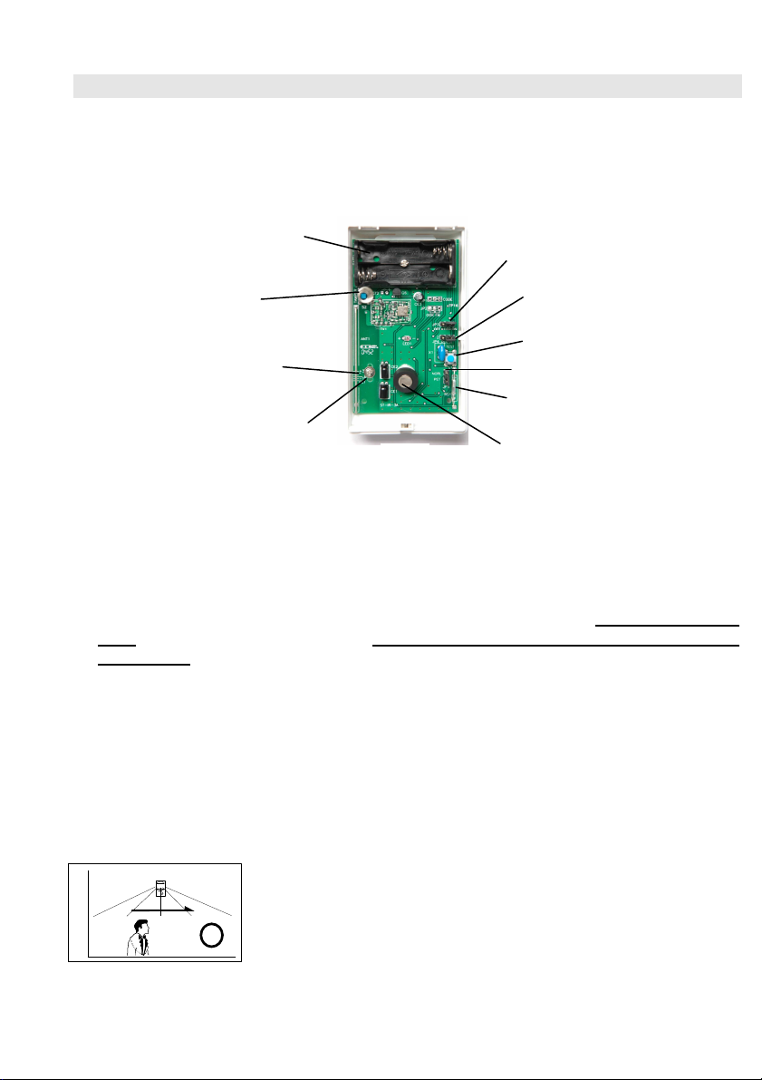
3A).
X 2
Switch
Jumper
Scale
Screw
INTRODUCTION
The PIR-3SP Passive Infrared Detector detects the movement of human body heat within its effective
coverage; thus, when an intruder crosses or enters the area, the resulting change in infrared energy
from the intruder will be detected and an alarm signal will transmit to the Base Unit.
AAA Battery
Tamper
LED ON/OFF
Jumper
Pulse Count
PCB
PCB
Fixing
Fig. 1
Test Switch
Jumper JP5
Reed Switch
Infrared Sensor
(Don’t touch)
PET IMMUNE DETECTOR
This detector is immune to one domestic pet up to 18 kg or 60 cm moving on the floor.
If animal activity takes place above 1 meter high, the pet immunity allowance will be significantly
reduced. Therefore Do Not aim the detector at stairways that animal can pass.
This detector should be mounted on the wall or corner at 2.0 m high and perpendicular to the
floor. Please note under this condition, the human motion within 1 m from the detector is
undetectable.
Do NOT use any mounting bracket with swivel adjustment. Should you must use a bracket, it
should be used for horizontal alignment only, do not tilt down.
Place the PCB at the “0” scale position. (for PCB version ST-IR-3B, or “P” scale for ST-IR-
And jumper JP5 at “PET” position.
It’s a must to verify the pet immune function after installation. In case animal is detected, sliding
the PCB to +1~+2 scale to test again (for PCB version ST-IR-3B, or to -1~0 scale for ST-IR-3A).
The weight of the animal can only be used as a reference. Other factors such as height and color
of fur could also affect the level of immunity.
IMPORTANT NOTE
To get the best sensitivity, PIR should be mounted to detect
movement of the intruder
detector.
a room rather than
across
toward
the
1
Page 2
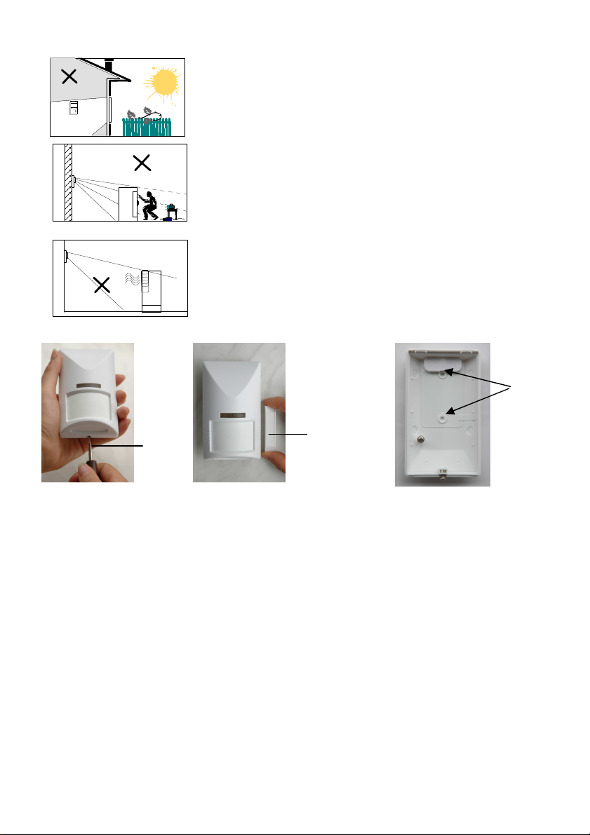
Do not install where the detector faces a window, since
Fig. 2
Holes
movement outside could cause unwanted alarms.
Make sure the detection area does not have obstructions (curtains,
screens, large pieces of furniture, plants, etc.) that could block the
pattern of coverage.
Open
Avoid placing the sensor in areas containing objects likely to
produce a rapid change in temperature, such as central heating
radiators or ducts (or heaters of any kind), air conditioners, open
flame, etc.
Screw
Test Button
Simulation
ON
OFF
$
Fig. 3
Fig. 4
Fig. 5
INSTALLATION
Refer to FIG. 2, and loosen the screw on the PIR bottom, and then remove the front cover.
1.
2. Insert two AAA alkaline batteries. Select “Installer Mode” on the Base Unit and enter the
Installer Code to gain access authority. Then select \Set Device\Enroll Device\Burglar
Sensor\Enter Zone No. to enroll the ID of PIR-3SP by pressing its TEST button on the PIR
board. You may change its various attributes under \Set Device\Change Device Setting\Burglar
Sensor Change, to fulfill different requirements.
Important Notice: In order to reset the microprocessor properly, before replacing the
batteries in the PIR-3SP, press the TEST button for 5 seconds to discharge the energy that
remains in the capacitor on the PC board. Otherwise, it may not restart.
After power on, wait one minute for sensor warm-up.
3.
Mount the base with two screws (refer to Fig. 4) or use Velcro tab provided at a selected
4.
location, and 2 m above the floor. Make sure the distance between PIR and Base Unit is within
RF transmission range.
2
Page 3

WALK TEST
It is essential to perform a walk test to verify optimum detection coverage. To do this, first hold the
TEST” button on the PIR-3SP board down for at least 3 seconds, until the LED turns ON→OFF
“
ON, then release the button. Afterward, the PIR-3SP enters “TEST” mode for 3 minutes. Replace the
cover of the PIR-3SP, then walk into the detection area at normal speed, while observing the LED
indicator.
pattern is not satisfactory, re-aiming the detector or adjusting the vertical pattern by sliding the PIR
board to -1 or 0 scale to test again.
Notes: 1. For the sake of convenience, the PIR is built in a reed switch; refer to its location on
The LED stays ON normally, and turns OFF when motion is detected.
Fig. 1. You may use a magnet to simulate the function of TEST button without opening
the case. When a magnet is placed close to the reed switch, the PIR responses as the
TEST button is pressed; refer to Fig. 5. And when a magnet is removed, the PIR
responses as the TEST button is released.
2. Test mode can be terminated before the 3-minute timeout by pressing the “TEST” button
again (or use a magnet to approach for a second) until the LED turns OFF. Afterward, it
returns to NORMAL mode.
3. In NORMAL mode, the PIR-3SP activates the transmitter when it initially detects
movement, then disables itself. The unit will resume operation only after about 3 minutes
with no further detection of movement. In other words, if installed in a heavy traffic area,
the PIR-3SP will not transmit until the area has been evacuated for 3 minutes. The
purpose of this feature is to reduce power consumption and prolong battery life.
If the detection
RADIO LINK TEST
Open the top cover of the PIR-3SP and press the TEST button on the PC Board, or use a
magnet to activate the reed switch, to see whether the Base Unit can receive the radio signal.
PULSE COUNT SELECTION
The PIR-3SP is equipped with a programmable pulse counter that can be set by placing the
jumper on the desired setting (2 or 4). The PIR-3SP automatically overrides to one-pulse mode
while in "TEST" mode.
2 pulses:
4 pulses:
This setting has high sensitivity of detection. Two pulses should be selected when the
detection range is longer (over 5 m)
Alarm signal will only be sent if 4 pulses are detected within approximately 1 minute.
This setting provides the maximum protection against false alarms caused by all types
of environmental disturbances.
LED ON/OFF SELECTION
To prevent the PIR from being discovered by an intruder, LED can be disabled by putting LED
ON/OFF jumper at OFF position. Nevertheless, the LED is enabled automatically when the
PIR-3SP is in “TEST” mode, even with the jumper at the OFF position.
→
3
Page 4

DETECTION PATTERN (PIR-3SP)
Top View
110°
2m
0.6m
Side View
1m 8m 12m
SPECIFICATIONS
Detector Type: dual element
Coverage Angle: 110
Pet-immunity: Up to 18kg, 60cm high
Effective Distance: max. 12 m @ ambient temp. 25℃
RFI Immunity: Ave. 20V/m (10~10000MHZ)
Detectable Speed: 0.3~1.5m/sec.
RF: 915Mhz, less than 10mW
Power: two AAA alkaline batteries
Current: 10uA @ standby, 12mA @ activation
Estimated Battery Life: 2 years (@ actuated 40 times/day)
Pulse Count: 2 or 4 pulses selectable
Mounting height: typical 2 m
Working Temperature : 0℃~40℃
Humidity: max. 95% RH
Size: 112 x 66 x 45 mm
Weight (w/o battery): about 90g
Note: This equipment has been tested and found to comply with the limits for a Class B
--Reorient or relocate the receiving antenna.
--Increase the separation between the equipment and receiver.
--Connect the equipment into an outlet on a circuit different from that to which the receiver
--Consult the dealer or an experienced radio/TV technician for help.
o
Digital Device, pursuant to part 15 of the FCC Rules. These limits are
designed to provide reasonable protection against harmful interference in
a residential installation. This equipment generates, uses and can radiate
radio frequency energy and, if not installed and used in accordance with
the instruction, may cause harmful interference to radio communication.
However, there is no grantee that interference will not occur in a particular
installation. If this equipment dose cause harmful interference to radio or
television reception, which can be determined by turning the equipment
off and on, the user is encouraged to try to correct the interference by one
or more of the following measures:
is connected.
Page 5

APPENDIX
The PIR-3SP can be used as a conventional detector (non pet-immune) if changing lens to LN-N
type (refer to Fig 6). And the model no. becomes PIR-3S.
Note: 1. When you use LN-N lens, you must place JP5 at “NORL” position.
2. The detection patter of PIR-3S is as below (max. distance 15m), and you may adjust PCB
scale position to fit detection coverage, or use bracket IRB-3 to adjust detection coverage.
Besides, you may change the installation height properly.
DETECTION PATTERN (PIR-3S)
Top View
110°
Side View
2.3m
1m 2.5m 8m 15m
Fig. 6
4
Page 6

Manual-BackCover.jpg (2544x3685x16M jpeg)
 Loading...