

Schweigen PKGA-600S1, PKKLS-ALBB9S1, PKKLS-ALBW9S1, PKGA-900S1, PKKLS-9GLASS1 Installation Guide
...Page 1

INSTALLATION GUIDE
HOME APPLIANCES
Isodrive 650
Revision V2
www.schweigen.com.au
Page 2

Index
1. Welcome ____________________________________________________________________________________________________ 3
2. Your Safety
Warning ______________________________________________________________________________________________________ 4
Before Installation __________________________________________________________________________________________ 4
Electrical Cord ______________________________________________________________________________________________ 4
Motor Features ______________________________________________________________________________________________ 5
General Notes on Installation and Use __________________________________________________________________ 5
Recommended Installation Distance ____________________________________________________________________ 5
Minimum Mounting Height ________________________________________________________________________________ 6
Avoidance of Back Flow __________________________________________________________________________________ 6
Safety of Children __________________________________________________________________________________________ 6
Replacement of Supply Cord ____________________________________________________________________________ 6
Why Flexi-duct ______________________________________________________________________________________________ 6
3. Description
Isodrive Motor _______________________________________________________________________________________________ 7
4. Installation
Roof Installation _____________________________________________________________________________________________ 9
Eaves Installation ___________________________________________________________________________________________ 11
Wall Installation _____________________________________________________________________________________________ 12
5. Back Draft Shutter System
Back Draft Shutter System for 150mm Ducting _________________________________________________________ 13
Installation for Back Draft Shutter System (150mm Ducting) __________________________________ 14
Back Draft Shutter System Fitment to Bell-mouth Adaptor ___________________________________ 15
6. Installation Examples
Single Motor Installation Example ________________________________________________________________________ 16
Twin Motor Installation Example __________________________________________________________________________ 17
7. Measurements
Measurements for Isodrive 650 ___________________________________________________________________________ 18
8. Flexible Duct
Shallow Roof Space ______________________________________________________________________ 20
Important Note ___________________________________________________________________________ 20
Securing Flexible Duct ____________________________________________________________________ 21
9. Maintenance
Roof Restoration or Cleaning ______________________________________________________________ 22
10. Warranty/Disclaimer _______________________________________________________________________________________ 23
Page 2
Page 3

1. Welcome
Thank you for purchasing your new Schweigen Isodrive system.
To get the maximum output from this unit, please read through this operating guide before use
and installation.
The operating guide contains important information on the correct use and maintenance of the unit,
as well as important safety notes. This will ensure your personal safety and the lasting value of your
Isodrive system.
We trust that you will enjoy your new Schweigen Isodrive system.
Please always retain your proof of purchase to aid in any warranty queries.
This appliance and its packaging are produced by processes that minimise waste and respect
the environment.
Please help us to continue this effort to protect the environment by using the appliance efciently
and dispose of the packaging in a responsible manner.
Model
Purchase Date
Purchase Location
Page 3
Page 4

2. Your Safety
WARNING
Please read this section thoroughly before attempting to operate the
appliance. Inspect your product upon receipt. Any damage or defects
MUST be reported within 48 hours, or no claim will be recognised.
DO NOT INSTALL THIS APPLIANCE IF YOU FIND IT DAMAGED.
If this product is installed damaged, the supplier, nor the retailer, will be
responsible for the costs associated with the repair, replacement, removal
or re-installation of the appliances.
1. This appliance is not intended for use by person/s (including children) with reduced physical,
sensory or mental capabilities, or lack of experience and/or knowledge. Unless the person has
been given supervision or instruction concerning the use of the appliance by a person responsible
for their safety. Children should be supervised to ensure that they do not play with the appliance,
it is not a toy.
Before Installation
We recommend this appliance to be installed or repaired by a qualied Schweigen Home
Appliances technician.
Please see our website www.schweigen.com.au for recommended installers.
It is dangerous to modify any part of this appliance. Modication of any kind, will immediately void
the warranty.
Do not install Isodrive motor to a non-Schweigen and/or non-silent rangehood. If you fail to do so,
your warranty will be voided.
The manufacturer declines all responsibility in case of failure to adopt proper safety measures.
Ensure that the location in which this appliance is installed, has good and permanent ventilation.
Please consult local laws and regulations and install in accordance.
Use an electrical connector with earth that is correct for your location.
Check that the voltage in your area corresponds to the appliance as indicated on the rating label.
Electrical Cord
Ensure the supply cord is not exposed to heat, chemicals or sharp objects. If the supply cord is damaged,
it must be replaced by the manufacturer, service agent or a similarly qualied person in order to avoid
a hazard.
Page 4
Page 5

2. Your Safety
This guide is for the installation of the motor used in the ISODRIVE systems after the canopy/
rangehood or bathroom extraction grill has been mounted on the wall or ceiling. (Refer to canopy/
rangehood or bathroom extraction unit installation manual).
NOTE: All PVC pipe and exi ducting measuremens are referring to inside measurements, unless
otherwise mentioned.
Motor Features
• Universal mounting, all position with IPX4 degree of weather protection
• Patented anti water intrusion system.
• Acoustic dome with super quiet, long vane, backward curved centrifugal fan.
• Airow is dependant on installation and the ducting used.
• Using a single 150mm exi duct run you should attain 650m
• The use of a smaller 125 pipe would result in a loss of airow.
3
/hr depending on the ducting installation.
• Simple installation: - Mounts onto a 100mm PVC pipe for ultimate strength and allows for easy
Dektite roof sealing.
• Industrial quality motor and fan made in Germany and rated at 40,000 hours.
• Motor is a high efciency PSC type and rated at 62W, costing around the same as a 60W light
globe to run.
• WARRANTY 10 YEARS return to manufacturer. Covers faulty manufacturing or components. It does
not cover normal wear and tear, chemical or storm damage, etc.
General Notes on Installation and Use
This fan unit is designed to be installed using 100mm PVC pipe as the initial connection duct to the fan
module, and is supplied with a 100mm PVC pipe to 150mm exible duct bell-mouth adaptor.
This fan is suitable for connection to multiple duct runs with a minimum inlet area of 11000 mm².
Ducting runs should be more than 2 metres away from the unit and no more than 4 - 5 metres (check
with supplier if longer duct length required). Flexible ducting must be extended sufciently to present
a smooth air passage with bends of at least the radius of twice the diameter of the duct.
WARNING: The Isodrive motor system must not be ducted into a wall cavity or a ceiling space, where
a build up of grease can occur and become a potential re risk. This will void your warranty.
NOTE: Fan module and dual foil exi-duct are acoustically matched. Use of semi-rigid or rigid ducting
will result in increased noise and void warranty. See installation instruction notes ‘Why exi-duct’.
Recommended Installation Distance
For Isodrive 650 motor, a minimum of 3 metres (approx.) is recommended.
Page 5
Page 6

2. Your Safety
NOTE: Installation closer than these distances may result in higher air noise level. Maximum duct
length 4 - 5 metres. Check with supplier if longer length is required. Do not reduce the duct size at
any time and avoid sharp bends.
Minimum Mounting Height
This fan unit is intended for mounting at a minimum height of 2.1 metres (measured to the lower part
of the fan impeller) above a oor or the ground.
Avoidance of Back Flow
Care should be taken to avoid the back ow of gases into the room from the open ue of gas or
other open re appliances.
Safety of Children
This fan is not intended for use by young children or inrm persons without supervision.
Replacement of supply cord
If the supply cord is damaged, it must be replaced by a service agent or suitably qualied person in
order to avoid a hazard.
Why Flexi-duct
Some internet sites strongly recommend the use of rigid ducting over fully exible ducting. This may
well be the case with conventional rangehoods with internal motor rangehood.
Schweigen’s unique Isodrive system works in the opposite way to conventional rangehoods, pulling
air through the hood and acoustically matched ducting producing almost silent high volume ow.
The use of a complete rigid or semi-rigid ducting system will allow an organ piping effect to occur;
like a didgeridoo where a noise is produced at one end of a hollow rigid pipe and the noise is
amplied out the other.
The Isodrive system puts the noise outside the house and it needs to be kept there.
Warning: Installation without the use of at least the minimum recommended length of acoustically
matched exi-ducting in the system will void performance expectations. Any installation problem
must be reported to Schweigen. Call outs relating to incorrect installation will result in a service fee
direct to the customer. Schweigen takes no responsibility for problems caused by faulty installation
and may void warranty. A preferred installer list can be obtained from Schweigen website
www.schweigen.com.au or call 1300 881 693.
Page 6
Page 7
3. Description
Isodrive Motor
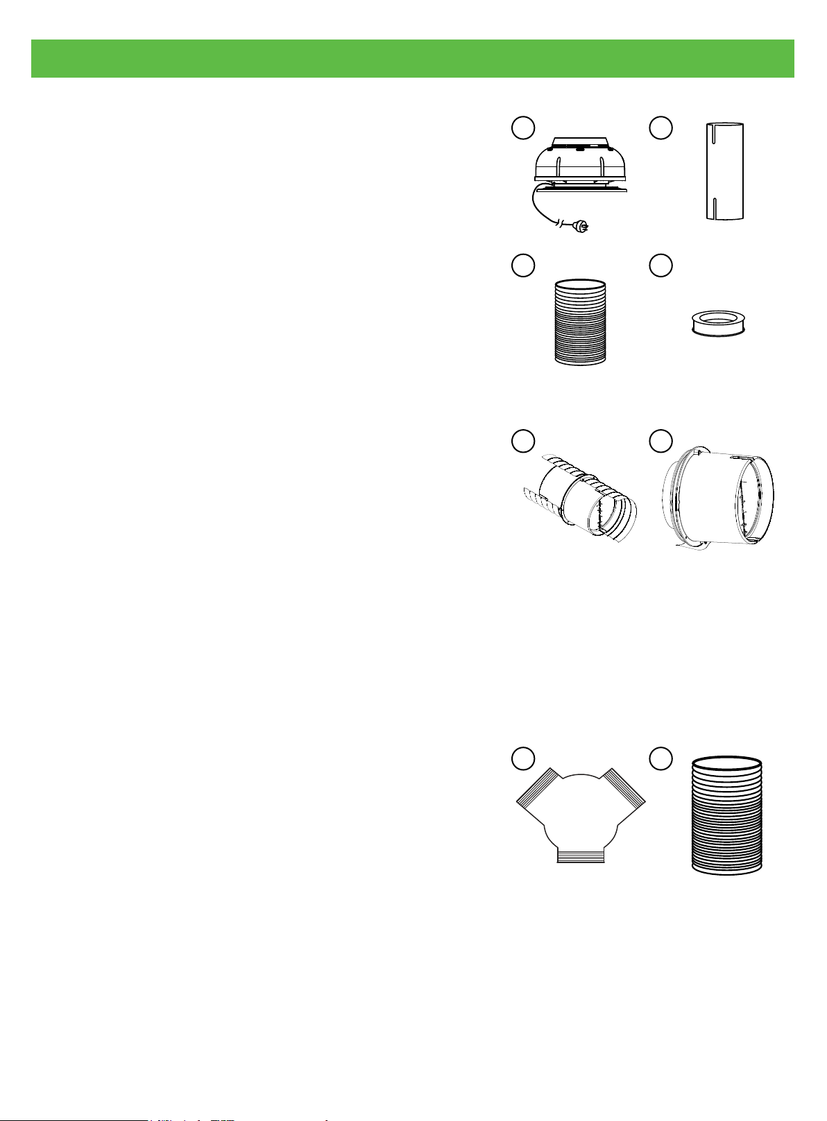
Included in the box:
1. Isodrive 650 motor (280W x 200H mm approx.)
Approx. 3 metre, 10amp cable and standard male plug
1
2. Fire resistant 100mm (110mm OD
Note: Cable cut-out at the bottom end only
3. Flexible ducting
Approx. 4 metres, 150mm (160mm OD
4. Bell-mouth adoptor ring
150mm duct to 100mm riser
Not included in the box:
A. (Optional) Back draft shutter for 150mm ducting
Refer to page 13 for more information.
B. (Optional) Back draft shutter tment to bell mouth
adaptor Refer to page 14 for more information.
) PVC riser pipe
1
) diameter
1 2
3
A
4
B
• Roof seal kit / Dektite
• Support straps for poly pipe which connects to the
roof truss
• Gaffer tape / electrical tape
• Zip ties
Additional S2 kit for twin 650 Isodrive motor:
i. One 150mm x 150mm x 200mm Y joint
ii. Flexible ducting
1
Approx. 3 metre, 200mm (210mm OD
1
OD refers to outside dimension.
) diameter
i
ii
Page 7
Page 8
4. Installation
Eaves Mount Option
Slot option
Roof Mount Option
Ensure
clearance
Mounting Flange
100 — 400
100mm PVC Pipe
Dektite
Bell-mouth adaptor
Connect to
rangehoood
Connect
to rangehood
20
min
Wall Mount Option
20
min
Min 90mm long PVC pipe
Bell-mouth adaptor
To fan
Electrical connection
between rangehood
and remote fan
module
Cover
Connect to main power
Rangehood
Page 8
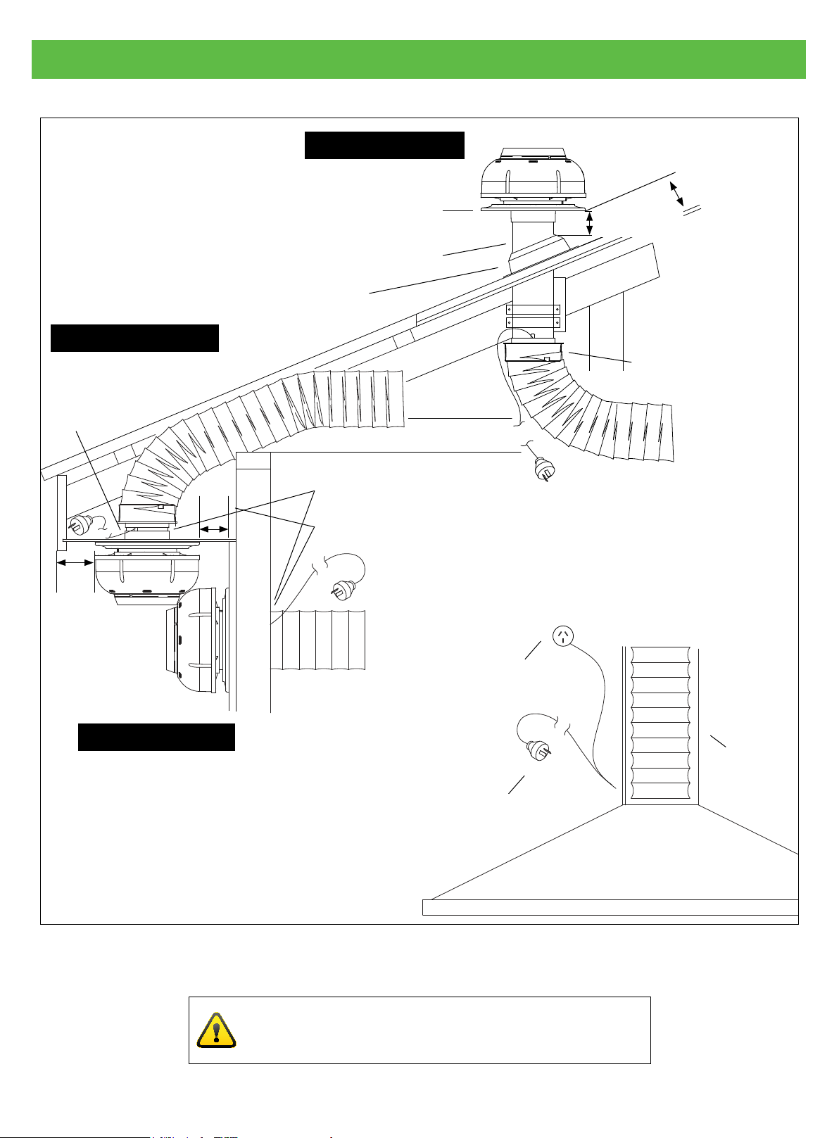
Figure 1 The three options for mounting the unit.
IMPORANT
For more exible ducting instructions, refer page 19.
Page 9

4. Installation
Roof Installation
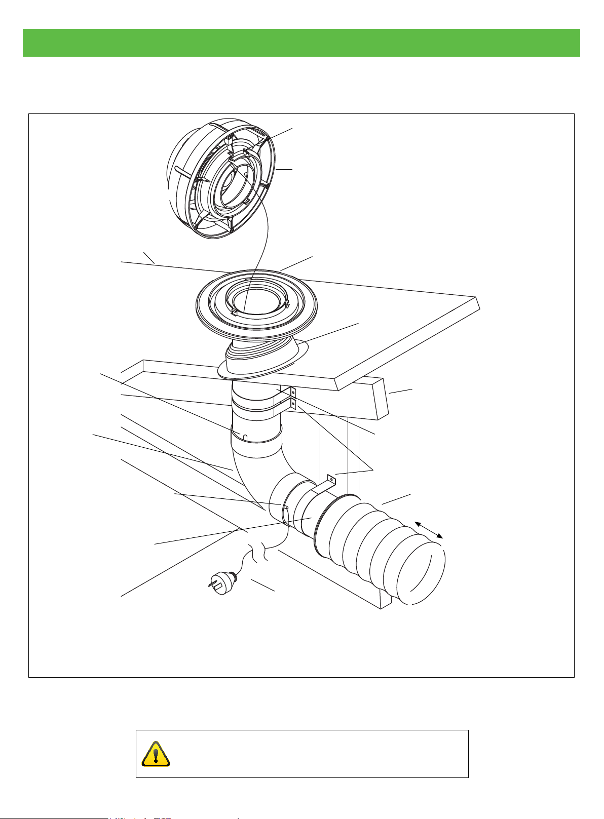
Mount the 100mm rigid PVC pipe securely to the beams, trusses or other appropriate structures, refer
gure 1.
The pipe should be mounted either vertical or perpendicular to the roof cladding with the roof
penetration being sealed using a Dektite or other sealing device.
Ensure that the pipe protrudes a minimum of 80mm past the top of the Dektite, checking that the
mounting ange clears the roof cladding at upper edge as shown in gure 1 — Roof Mount Option.
Maximum recommended protrusion is 400mm. Fit mounting ange, refer gure 2, to pipe using silicon
sealant, then tape in position until sealant has set.
Pass power cord and plug through mounting ange and pipe, then out the slotted end of the PVC
pipe for connection to the female plug coming from the canopy/rangehood or authorized switching
mechanism in bathroom application, refer gure 2.
Fit fan module to mounting ange by placing in position, rotating clockwise to engage bayonet ngers
then secure by screwing in locking screw (while holding fan module rmly in the fully clockwise position),
refer gure 2.
(Recommended duct length: 3 metre)
Page 9
Page 10
4. Installation
Roof Installation
Roof Clading
Locking Screw
Fan Module
Mounting Flange
Dektite
Slot option
Optional bend
Slot pipe for power
cord exit. Cover with
ducting tape if required
Bell-mouth adaptor
NOTE: Ensure that power cord is feed
through exit slot and is not allowed to
double back restricting fan inlet.
Roof Frame
100mm PVC Pipe
Secure pipe to structure
150mm exible ducting
5 metre max
Connect to
rangehood
Power cord
Page 10
Figure 2
IMPORANT
For more exible ducting instructions, refer page 19.
Page 11
4. Installation
Eaves Installation
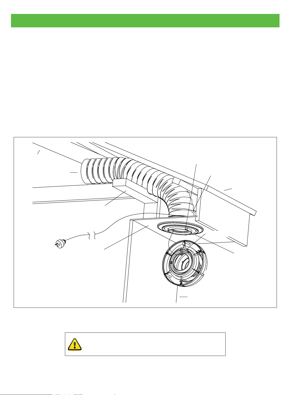
After ensuring sufcient clearance exists for the mounting ange and ducting, refer gure 1, cut a
circular hole 165mm Ø, maintaining adequate clearances. The eaves sheeting should be reinforced.
Pre-drill mounting ange recess. Refer gure 3.
If access to the eaves space is restricted, before xing mounting ange to eaves, preassemble
mounting ange, PVC pipe, bell-mouth adaptor and exi-duct then feed up into roof space.
Remember to run power cord through the assembly and out the slotted PVC pipe wall, refer gure 3.
Fit fan module to mounting ange by placing in position, rotating clockwise to engage bayonet
ngers then secure by screwing in locking screw (while holding fan module rmly in the fully clockwise
position).
Ensure that one of the three
bayonet ngers is accessable
Roof Frame/Truss
for securing locking screw
150mm Ducting
Top Plate
Eaves
NOTE: Ensure that power cord
is feed through exit slot and is
not allowed to double back
restricting fan inlet.
Bell-mouth Adaptor
Roof Cladding
Locking Screw
Pre-drill mounting
ange recess and
secure to reinforced
eaves sheet using #8
self tapping screws
Wall
Figure 3
IMPORANT
For more exible ducting instructions, refer page 19.
Page 11
Page 12
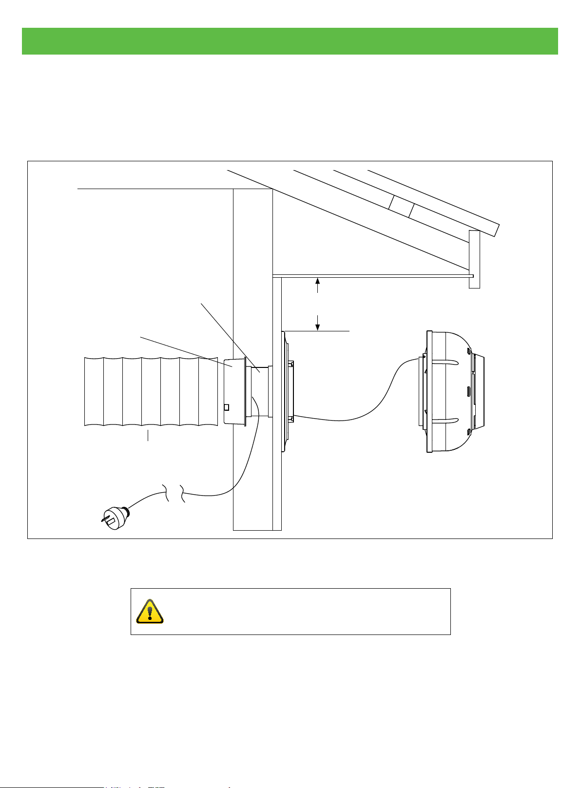
4. Installation
Wall Installation
The installation should be similar to eaves mounting if access to the inside is limited, but if unrestricted.
Refer to EAVES INSTALLATION and gure 4.
Min 90mm long PVC pipe
Bell-mouth Adaptor
Flexible 150mm ducting
Min 20mm
NOTE: Ensure that power cord is feed
through exit slot and is not allowed to
double back restricting fan inlet.
Figure 4
Page 12
IMPORANT
For more exible ducting instructions, refer page 19.
Page 13
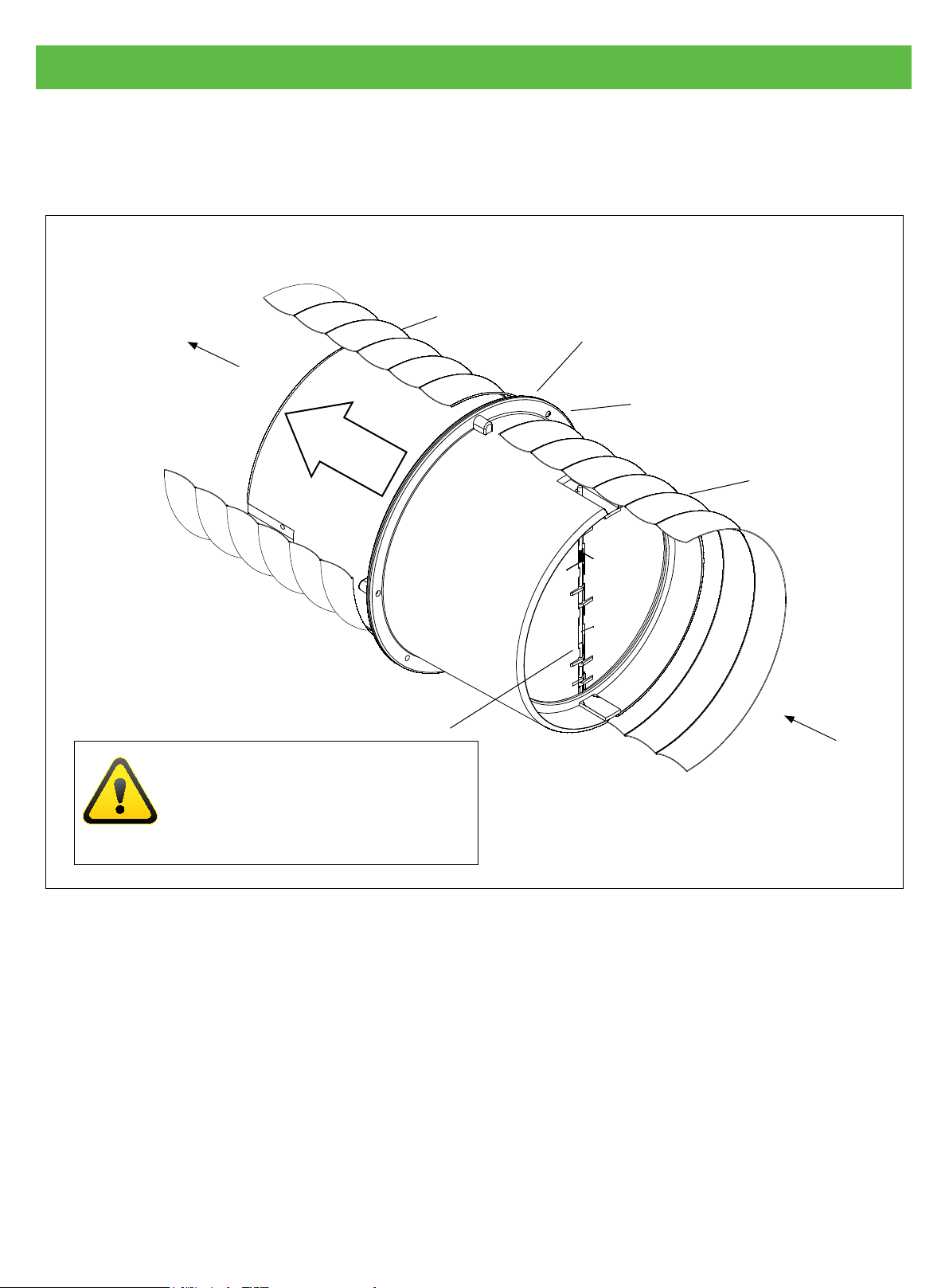
5. Back Draft Shutter System
Back Draft Shutter System for 150mm Ducting
This back draft shutter suitable for Isodrive 650 motor only.
To fan
Direction
of airow
Air ow
Mount shutter system as close
to Isodrive fan as practicable
IMPORANT
If shutter system is mounted in the
horizontal position, shutter shaft
should be vertical.
Flexi duct
Use duct tape to secure
exi duct to shutter system
In line shutter system
Flexi duct
Direction
of airow
Part number: 150mm in line BDSS.
Figure 5
Page 13
Page 14
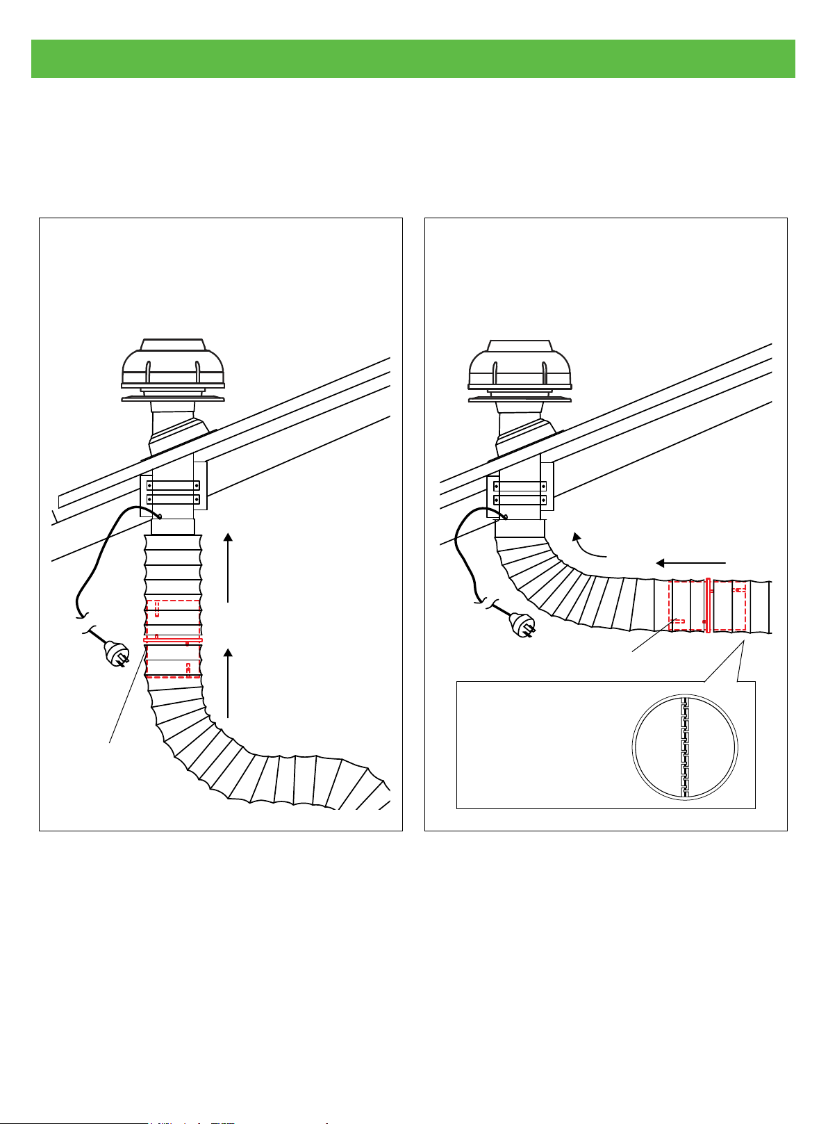
5. Back Draft Shutter System
Installation Example for Back Draft Shutter System
(150mm Ducting, refer to gure 5)
This back draft shutter suitable for Isodrive 650 motor only.
Verticle Installation
Figure 6 shows an example of verticle
installation. If space is allowed, it could be
installed near the ranghood outlet.
Air ow
Horizontal Installation
If you have a narrow roof space, you can
install the back draft shutter horizontally,
refer to gure 7.
Air ow
Back draft shutter
Back draft shutter
NOTE: Shutter
shaft should be
placed vertically.
Figure 6 Figure 7
Page 14
Page 15
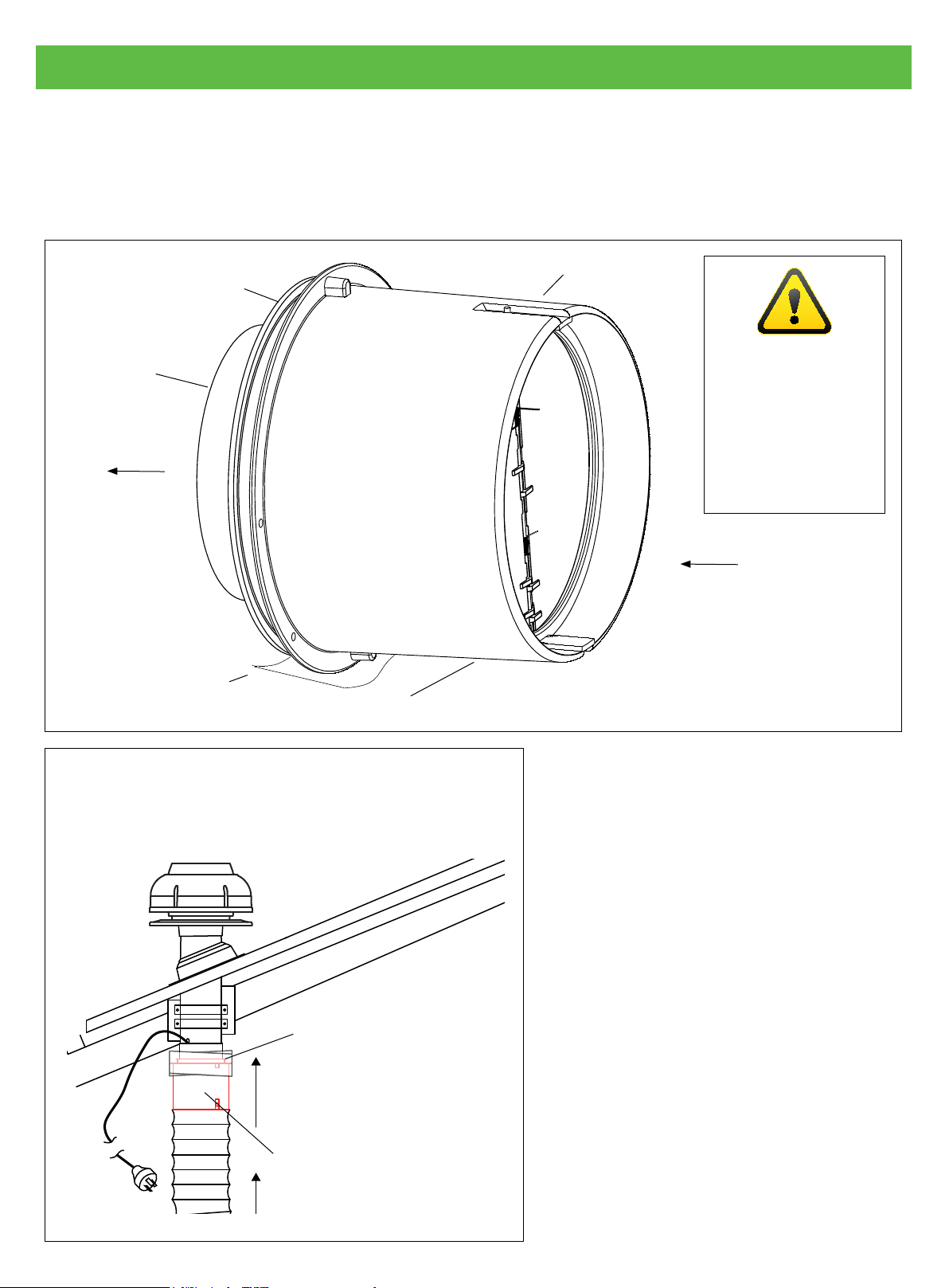
5. Back Draft Shutter System
Back Draft Shutter System Fitment to Bell-mouth Adaptor
This back draft shutter suitable for Isodrive 650 motor only. This back draft shutter system cannot be
installed in eave type installation.
Back draft shutter system
Bell-mouth adaptor
100mm pipe
to fan
To fan
IMPORANT
If shutter system
is mounted in the
horizontal position,
shutter shaft should
be vertical.
Tape over anges
Fit exi-duct over shutter assembly
Verticle Installation
Figure 9 shows an example of verticle installation.
Tape over anges
Direction
of airow
Part number: 150 MMBDSS
Figure 8
Air ow
Back draft shutter system
Figure 9
Page 15
Page 16
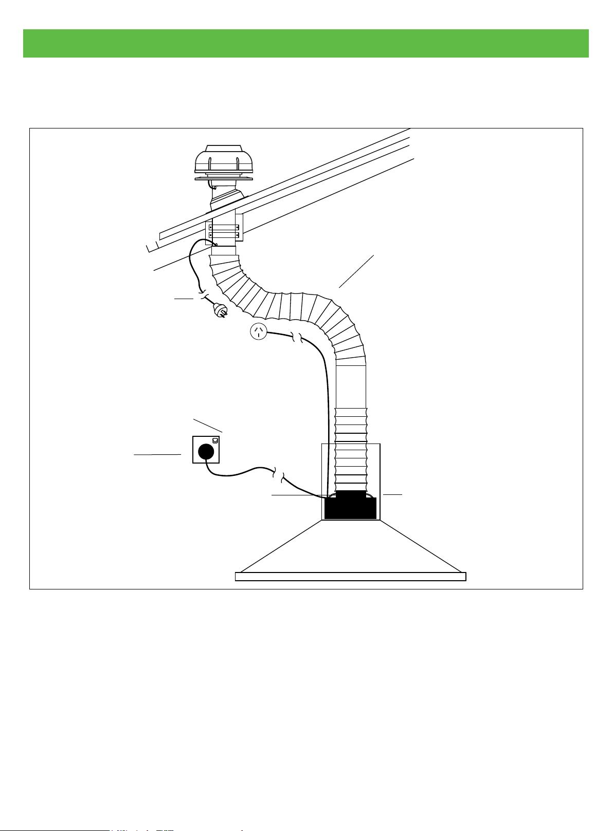
6. Installation Examples
Single Motor Installation Example
Connect to rangehood
Use smooth owing curves for
maximum airow. Remove
excess ducting by trimming to
length. DO NOT install motor in
straight line to rangehood.
Connect to motor
Connect to
main power
Use reducer 150mm to 200mm
Cover
Figure 10
Page 16
Page 17
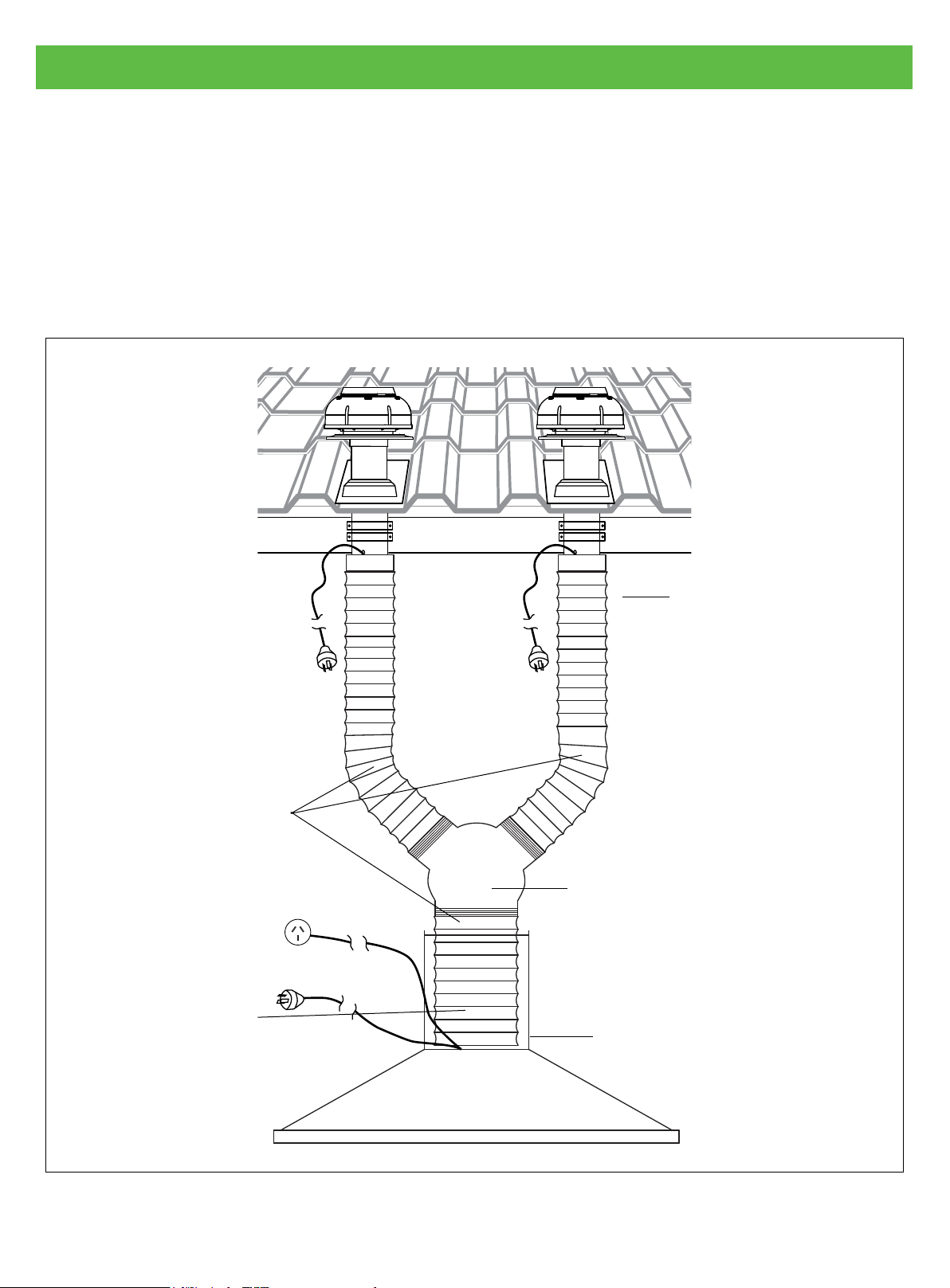
6. Installation Examples
Twin Motor Installation Example
Where two motors are to be used, follow the below methods for each motor then join into the “Y”
piece prior to joining ducting to the canopy / rangehood. Refer gure 11.
The two motors can be wired by one of the following methods:
• Wired into one plug by an electrician
• A double adaptor plugged into the lead from the canopy / rangehood
Roof mount option Roof mount option
Ensure exible ducting
is fully extended and as
short as possible. Use
smooth owing curves
for maximum air ow.
Remove excess ducting
by trimming to length.
Always keep ducting taut.
Flexi ducting 200mm
Try to keep length of
exible ducting as
even as possible other
wise motors will draw
air off each other
‘Y’ Junction for Twin 650 Motor
Installation
150 x 150 x 200mm
For current models with 200mm
opening (S2 Kit available)
Flue cover
Figure 11
Page 17
Page 18
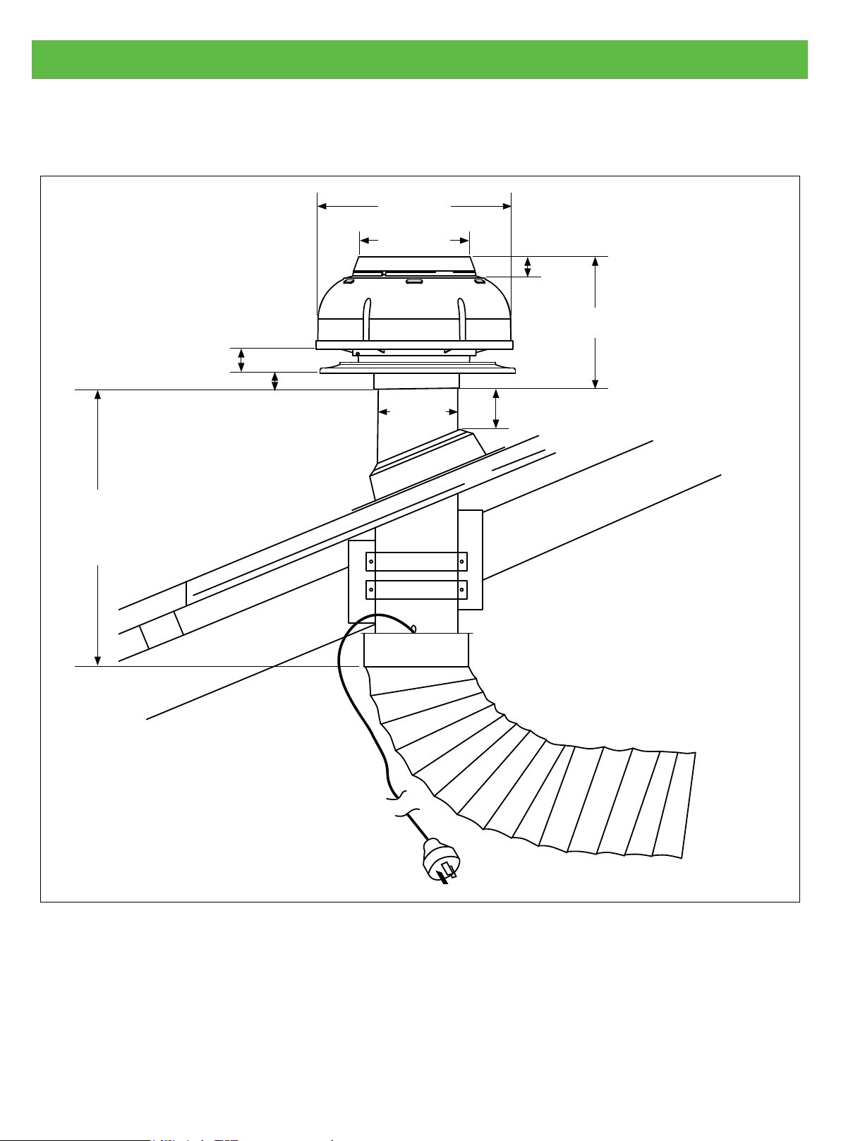
7. Measurements
Measurements for Isodrive 650
278mm
157mm
35mm
29mm
28mm
195mm
370mm
110mm
35mm minimum
Page 18
Figure 12
Page 19
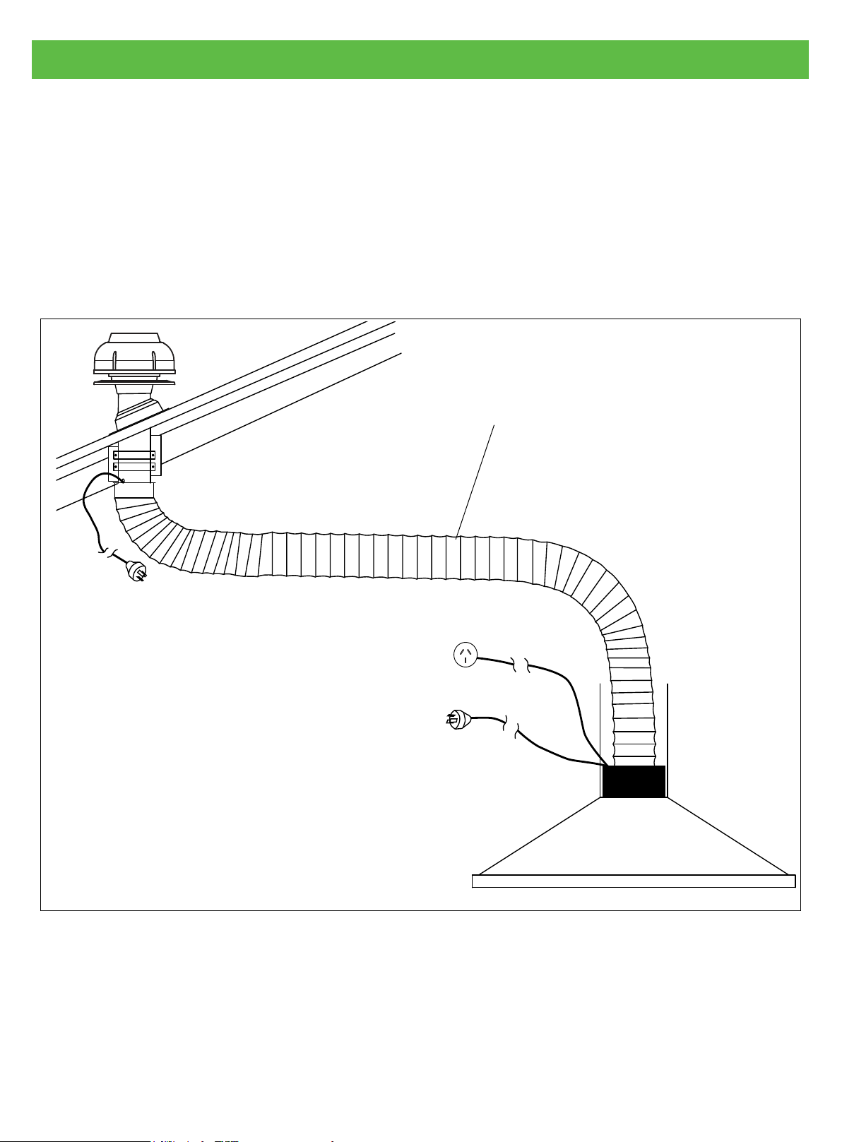
8. Flexible Duct
Flexible Duct
Flexible ducting must be fully extended and cut to the required length upon installation, refer to
gure 13. Maximum fan performance will not be achieved unless the ducting is fully extended. Failure
to fully extend ducting results in a smaller air passage and lower airows. Incorrect installation may
reduce airow or increase noise levels. Call outs relating to incorrect installation will result in a service
fee directed to the customer. Schweigen will take no responsibility for problems caused by faulty
installation. Installation should be done by a qualied technician. A preferred installer list can be
obtained from Schweigen website www.schweigen.com.au.
Please keep the exible duct taut,
3 metres in length (optional)
NOTE: In shallow roof spaces
extend exible duct horizontally
Figure 13
Page 19
Page 20
8. Flexible Duct
Shallow Roof Space
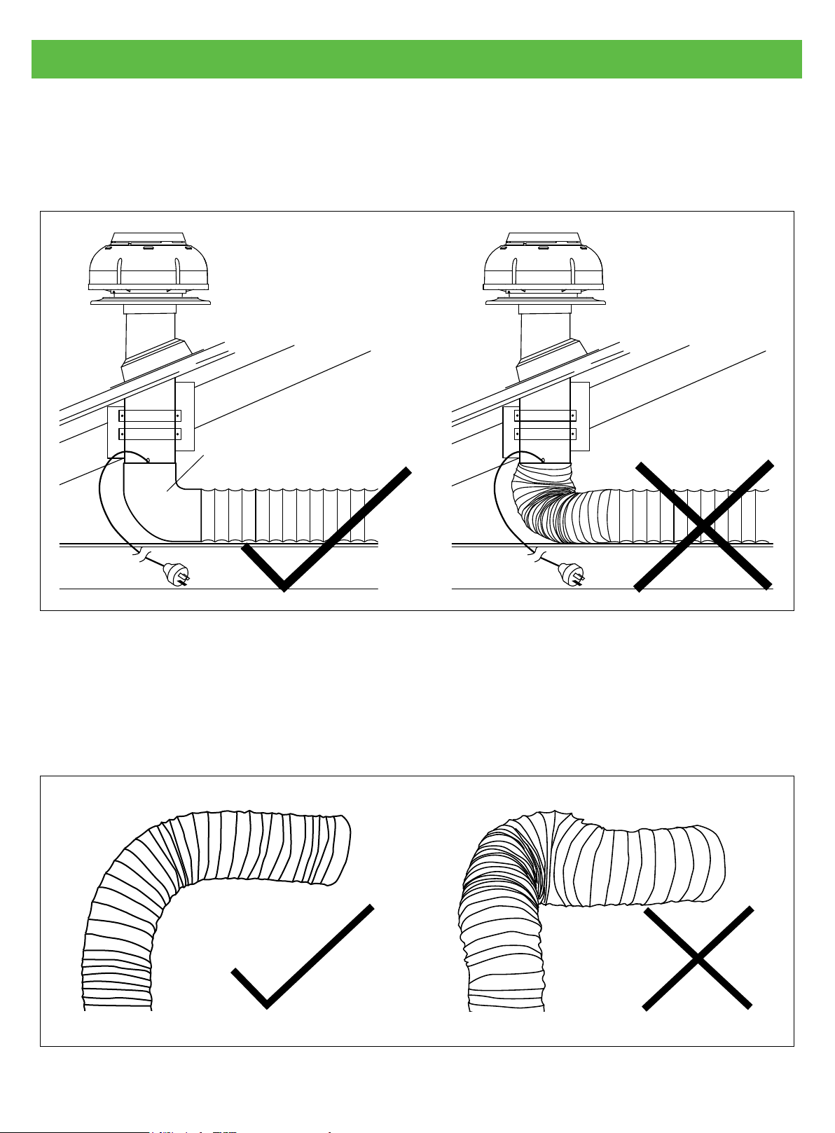
In shallow roof spaces, do not crush or kink exible ducting, as it will reduce air ow severely. 90
degree curve PVC or galvanise curve can be used as a substitute for the bend, refer to gure 14.
90 degree curve PVC
or galvanise curve
Figure 14
Important Note
Please do not crush or kink exible ducting, as it will reduce air ow and may cause noise to occur
through the system. Ducting needs to be kept taut at all times.
Page 20
Figure 15
Page 21

8. Flexible Duct
Securing Flexible Duct
Flexible duct must be installed with supports at maximum intervals of 1.5 metres. Flexible ductwork
can be supported by using gaffer or electrical tape. Provided that it does not restrict the internal
diameter of the ducting. Ducting installed looped over hanging beams should be installed in such
a manner as to ensure the changes of direction are gradual. Support of the ducting with the use of
hangers may be require, see option 2.
NOTE: Ducting should be kept taut at all times.
Option 1
Secure the exible
duct to the beam
Option 2
Support exible duct
by using hangers.
NOTE: Care shall
be taken to
minimize sagging or
snaking of the duct
between supports.
Gaffer or
electrical tape
Hanger
Gaffer or electrical tape
Figure 16 Examples of securing ducting
Page 21
Page 22

9. Maintenance
Roof Restoration or Cleaning
Before doing your roof restoration or cleaning, please completely cover the outside motor system
and avoid all chemical contact.
IMPORANT
Any damages caused
by the use of chemical
products are not covered
by warranty.
Figure 17 Avoid chemical contacted to motor system
Page 22
Page 23

10. Warranty/Disclaimer
Warranty
Isodrive motor has a 10-Year replacement product warranty. This is a change over warranty. The
consumer is responsible for any charges associated with removal of the faulty unit and installation
of the new unit. The customer is also responsible for any freight charges incurred in this change
over process.
(See warranty for more information)
Disclaimer
Under our policy of continuous product development, product specications may change without
notice. Prospective purchasers should therefore check with the retailer to ensure this publication
correctly describes the products being offered for sale. All information supplied is to be used for
general reference purposes only and is on the understanding that Schweigen Home Appliances will
not be liable for any loss, liability or damage of whatever kind arising as a result of any reliance upon
such information. All pictures used in the guide are for illustrative purposes only.
Page 23
Page 24

HOME APPLIANCES
Distributed by:
Unit 102/45 Gilby Road,
Mt Waverley 3149 Victoria.
1300 881 693 (EST)
www.schweigen.com.au
 Loading...