

Page 1
INSTRUCTION MANUAL
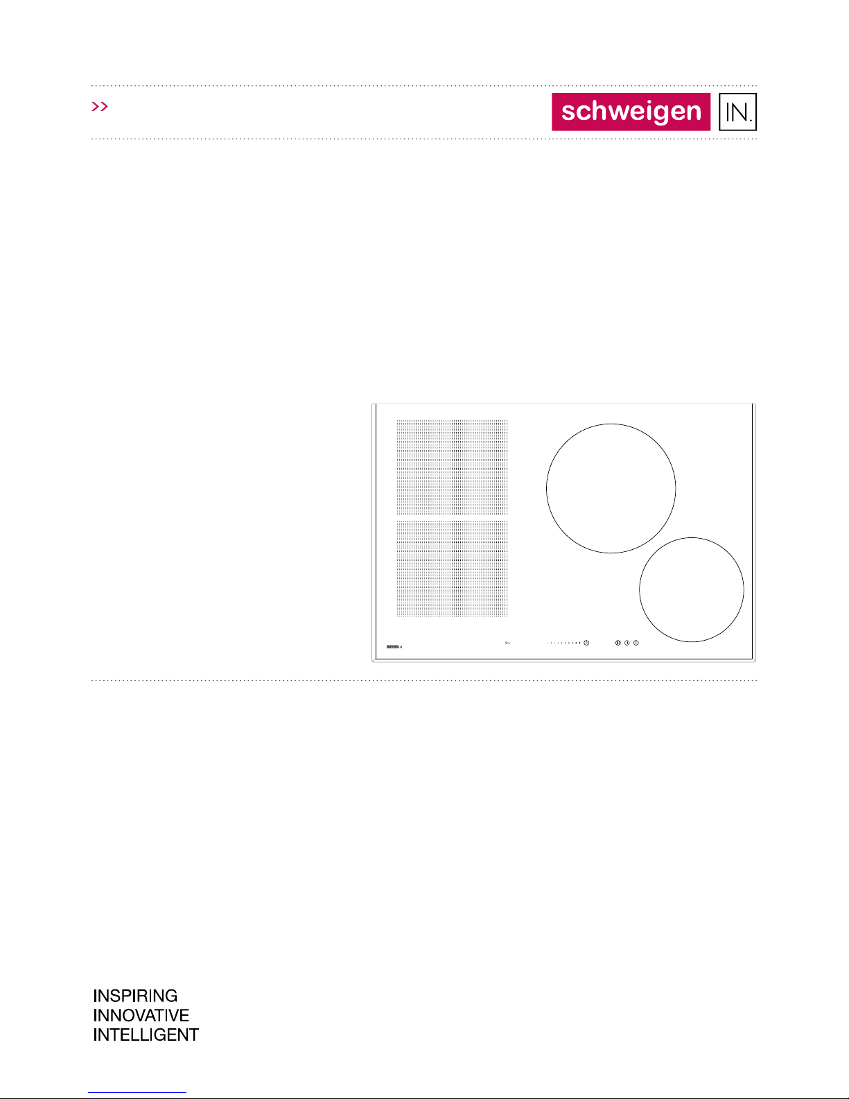
INID77
INDUCTION COOKTOP
cooktop/INDUCTION/ceran/77cm
Installation / Operation / Maintenance
Revision V1.0
INID77 (PBZ4VI527AFTB4SC)
Page 2

Thank you for purchasing this Schweigen IN
appliance.
To achieve the optimal performance from your
appliance, and to avoid the risk of accident or
damage, it is essential to read this manual before
installation and rst time use.
This guide contains important information on the
use and maintenance of the appliance, as well as
important safety notes.
Your appliance has been thoroughly checked for
safety and functionality before being packaged
and leaving the manufacturer.
Please keep this instruction manual in a safe
place so you can refer to it at any time.
IMPORTANT!
The appliance should only be operated when
you have read and understood this manual
thoroughly.
The appliance can be only used for the purpose
for which it was designed. Any other use is
improper and can be dangerous.
Installation, regulation and maintenance
of gas and electrical appliances should only
be carried out by qualied and authorised
professionals familiar with Australian
Appliance Industry regulations.
Upon collection or delivery of the appliance,
any damage or defects must be reported
within 48 hours to your retailer or
Schweigen Customer Service, in order
to recognise any claim.
The manufacturer reserves the right to
introduce changes, which do not aect the
operation of the appliance, at any time.
Page 2
WELCOME
Page 3

Page 3
INDEX
Welcome ......................................................... 2
Important Safety Information ...................... 4
How to Save Energy ....................................... 6
Unpacking ....................................................... 6
Disposal of the Appliance .............................. 7
Description of the Appliance
Control Panel ............................................................... 8
Specication .................................................. 8
Installation
Ventilation .................................................................... 9
Combustible Surfaces ................................................ 9
Requirements for the Placement of Installation ... 9
Notes for the Installer ............................................. 10
Gas Connection .......................................................... 11
Universal Gas - ULPG ................................................ 11
Natural Gas ................................................................. 11
Installing the Gas Cooktop ...................................... 13
Adapt the Cooktop to a Particular Type of Gas .... 14
Table of Burner & Injector Characteristics ........... 14
Adjust the Valves for A Reduced Flow .................. 14
Adjust the Valves ..................................................... 15
Operation
Turn on the Appliance ............................................... 16
Child Lock ................................................................... 16
Release the Child Lock ............................................. 16
Control Panel Indications ........................................ 16
Residual Heat Indicator ............................................ 17
Energy Eciency ...................................................... 17
Choice of Cookware .................................................. 17
Cookware Lids ............................................................ 17
Burner Control Dial .................................................... 17
Adjust Flame ............................................................. 18
Cleaning and Maintenance
Burners, Trivets .......................................................... 19
Regular Inspections .................................................. 19
In the Event of A Gas Leak Or Suspect Fault 20
Troubleshooting
Emergency Procedure ............................................. 21
Page 4

Page 4
SAFETY INSTRUCTIONS
Warning: The appliance and its accessible parts
become hot during use. Care should be taken to
avoid touching heating elements.
This appliance is not intended for use by anyone
(including children) with reduced physical, sensory
or mental capabilities, or lack of experience and
knowledge, unless they are supervised and/or have
been given instruction for use of the appliance.
Cleaning and user maintenance cannot be
performed by children without supervision.
Children should be supervised to ensure that they
do not play with the appliance.
Children shall not play with the appliance. Cleaning
and user maintenance shall not be made by
children.
Warning: Unattended cooking on a cooktop with
fat or oil can be dangerous and may result in re.
NEVER try to extinguish a re with water, but
switch o the appliance and then cover ame e.g.
with a lid or a re blanket.
Warning: Danger of re: do not store items on the
cooking surfaces.
Caution: The cooking process has to be
supervised. A short term cooking process has to be
supervised continuously.
Page 5

SAFETY INSTRUCTIONS
Page 5
Warning: If the surface is cracked, switch o the
appliance to avoid the possibility of electric shock.
Metallic objects, such as knives, forks, spoons and
lids should not be placed on the cooktop surface.
After use, switch o the cooktop element by its
controls and do not rely on the pan detector.
The appliance is not intended to be operated by
means of an external timer or separate remotecontrol system.
You should not use steam cleaning devices to clean
the appliance.
Page 6

Page 6
• Before using the induction cooktop for the rst
time, carefully read its user manual. This will
ensure user safety and prevent damage to the
appliance.
• If the induction cooktop is operated in immediate
vicinity to the radio, television set or other
radio-frequency-emitting device, make sure
that the cooktop’s touch sensor controls operate
correctly.
• The cooktop must be connected by a qualied
installer.
• Do not install the appliance near a refrigerator.
• Furniture, where the cooktop is installed must
be resistant to temperatures up to 100°C. This
applies to veneers, edges, surfaces made of
plastics, adhesives and paints.
• The appliance may only be used once tted in
kitchen benchtop. This will protect the user
against touching any live parts.
• Repairs to electrical appliances may only be
conducted by specialists. Improper repairs can be
dangerous to the user.
• The appliance is not connected to mains power
when it is unplugged or the main circuit breaker
is switched o.
• The power cord should be accessible after
appliance has been installed.
• Ensure that children do not play with the
appliance.
• This appliance should not be used by persons
(including children) with physical, mental
or sensory handicaps, or by those who are
inexperienced or unfamiliar with the appliance,
unless under supervision or in accordance with
the instructions as communicated to them by
persons responsible for their safety.
• Persons with implanted devices, which support
vital functions (eg, pacemaker, insulin pump, or
hearing aids) must ensure that these devices
are not aected by the induction cooktop (the
frequency of the induction cooktop is 20-50 kHz).
• Once power is disconnected all settings and
indications are erased. When electric power is
restored, caution is advisable. If the cooking
zones are hot, “ ” the residual heat indicator
will be displayed. The child lock key will also
be displayed.
• Built-in residual heat indicator can be used
to determine if the appliance is on and if it
is still hot.
• If the mains socket is near the cooking zone,
make sure the power cord does not touch any
hot areas.
• When cooking using oil and fat do not leave the
appliance unattended, as there is a re hazard.
• Do not use plastic containers and aluminium
foil. They melt at high temperatures and may
damage the cooking surface.
• Solid or liquid sugar, citric acid, salt or plastic
must not be allowed to spill on the hot cooking
zone.
• If sugar or plastic is accidentally spilled onto
the hot cooking zone, rst wait for it to cool,
then wipe o the spill with a clean, damp cloth
(do not use cleaning agents as these can cause
discolouration).
• If spillage has set hard, ensure the cooktop
is cool, then gently scrape away using an
appropriate sharp scraping utensil. Wipe o
any remaining residue with a clean, damp cloth
(do not use cleaning agents as these can cause
discolouration).
SAFETY INSTRUCTIONS FOR USE
Page 7

SAFETY INSTRUCTIONS FOR USE
Page 7
• When cooking on induction cooktop only use
pots and pans with a at base having no sharp
edges or burrs as these can permanently scratch
the cooking surface.
• The induction cooktop cooking surface is
resistant to thermal shock. It is not sensitive to
cold or heat.
• Avoid dropping objects on the cooking surface. In
some circumstances, impacts such as dropping a
bottle of spices, may lead to cracks and chipping
of the cooking surface.
• If any damage occurs, food or liquids may seep
into the live parts of the induction cooktop
through damaged areas.
• If the cooking surface is cracked, switch o
power to avoid the risk of electric shock.
• DO NOT use the cooking surface as a cutting
board or work table.
• DO NOT place metal objects such as knives, forks,
spoons, lids and aluminium foil on the cooking
surface.
• DO NOT install the cooktop over a heating unit,
dishwasher, refrigerator, freezer or washing
machine.
• If the cooktop has been built into the kitchen
worktop, metal objects located in a cabinet
below can be heated to high temperatures
through the air owing from the cooktop
ventilation system. You must install a partition
(see Fig. 2).
• Please follow the instructions for care and
cleaning of induction cooktop. In the event of
misuse or mishandling warranty may be void.
Page 8

Using the electricity in a responsible manner
not only saves money, but also helps protect the
environment. So let’s save electricity! This is how
it’s done:
• Use the correct cookware.
Cookware with at and a thick base can save up
to 1/3 of electricity. Please remember to cover
cookware with the lid, otherwise electricity
consumption increased four times!
• Always keep the cooking zones and
cookware bases clean.
Dirt prevents proper heat transfer. Often burnt
stains can be removed only with agents harmful
to the environment.
• Avoiding unnecessary lifting the lid to peek into
the pot.
• Do not install the cooktop in the immediate
vicinity of refrigerator / freezer.
The electricity consumption is unnecessarily
increased.
This appliance is marked with the symbol of the
crossed-out waste container.
This marking means that the appliance must not be
disposed of together with other household waste
after it has been used. The user is obliged to hand
it over to waste collection centre collecting used
electrical and electronic goods. The collectors,
including local collection points, shops and local
authority departments provide recycling schemes.
Proper handling of used electrical and electronic
goods helps avoid environmental and health
hazards resulting from the presence of dangerous
components and the inappropriate storage and
processing of such goods.
The appliance was packed to protect it from
damage at the time of transport. After unpacking,
please dispose of all elements of packaging
in a way that will not cause damage to the
environment. All materials used for packaging
the appliance are environmentally friendly; they
are 100% recyclable and are marked with the
appropriate symbol.
IMPORTANT! Keep the packaging
material (bags, styrofoam pieces, etc.) out of
reach of children during unpacking.
Page 8
SAVING ENERGY UNPACKING
DISPOSAL
Page 9
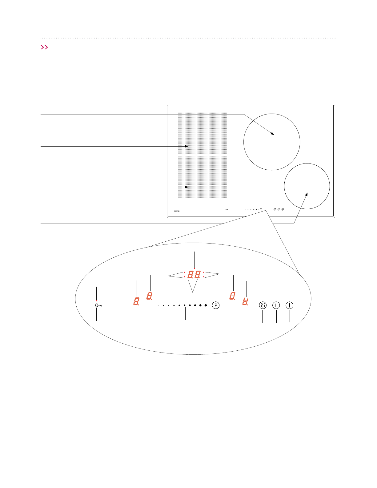
CONTROL PANEL
SENSOR FIELDS:
1. On/o sensor eld
2. Heat setting selection sensor eld
3. Cooking zone indicator
4. Timer display
5. Timer indicator light
6. Booster sensor eld
7. Stop ’n’ go function sensor eld
8. Keep Warm function sensor eld
9. Child lock sensor
10. Child lock indicator light
11. Kitchen timer indicator light
COOKTOP DESCRIPTION
CONTROL PANEL
Induction cooking zone
booster (rear right)
Induction cooking zone
booster (rear left)
Induction cooking zone
booster (front left)
Induction cooking zone
booster (front right)
1
2
3
3
3
4
5
6
78
9
10
11
5
3
Page 9
DESCRIPTION OF THE APPLIANCE
Page 10
Page 10
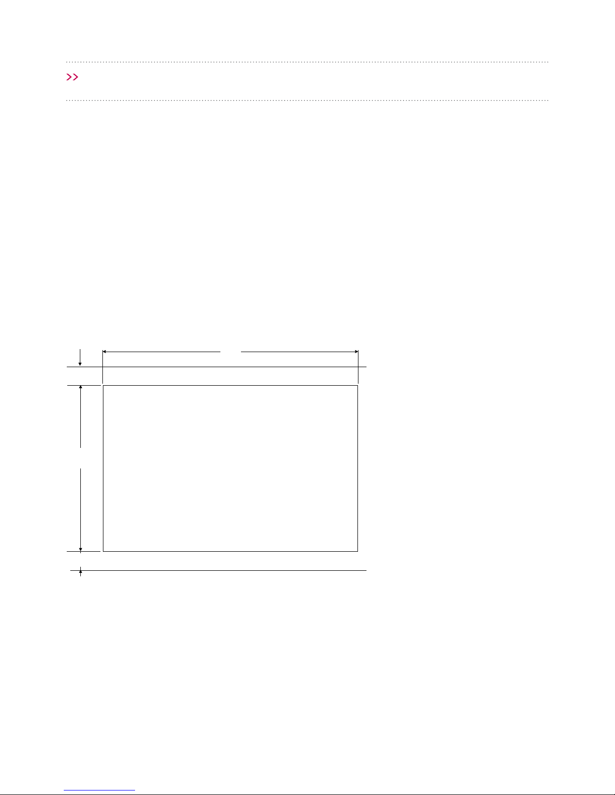
INSTALLATION
RECESSING THE BENCHTOP
Benchtop thickness should be 28 - 40 mm, with a
width of at least 600 mm. The benchtop must be
at and level, and the edge of the benchtop near
the wall must be sealed to prevent ingress of water
or other liquids.
There should be sucient spacing around the
opening in particular — at least 50 mm distance to
the wall and 60 mm distance to the front edge of
benchtop.
The distance between the edge of the opening and
the side wall of the benchtop should be a minimum
of 55 mm.
The benchtop must be made of materials –
including veneer and adhesives – resistant to
a temperature of 100°C. Otherwise the veneer
could come o or the surface of the benchtop can
become deformed.
The edge of the opening should be sealed with
suitable materials to prevent ingress of water.
The benchtop opening must be cut to dimensions
as shown in Figure 1.
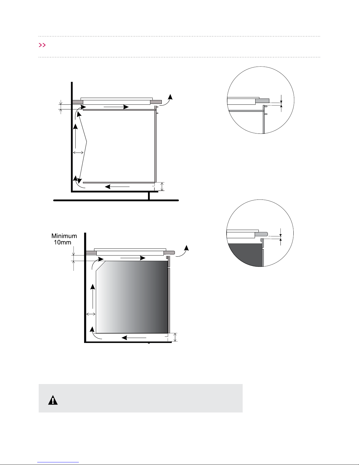
Ensure there is a minimum clearance of 25 mm
below the cooktop to allow proper air circulation
and prevent overheating. See Figure 2.
750
094
nim
06
nim
05
321
Figure 1. Cutout
Measurements in mm.
Page 11
INSTALLATION
Page 11
Figure 2.
750
094
06
05
Installing cooktop in kitchen
cabinet benchtop.
Installing cooktop in kitchen
benchtop above oven with
ventilation.
5 10mm-
5 10mm-
25mm
30mm
20mm
321
20mm
10mm
10mm
Do not install the cooktop above the oven without ventilation.
Page 12
INSTALLATION
Page 12
INSTALLING THE COOKTOP
• Using an electrical cord, connect the cooktop
according to electrical diagram provided.
• Remove dust from the worktop, insert cooktop
into the opening and press in rmly (Fig. 3).
CONNECTING TO ELECTRICAL MAINS
321
IMPORTANT
Electrical connection must be made by an
authorised qualied installer. Do not make
any alterations to the cooktop’s electrical
system.
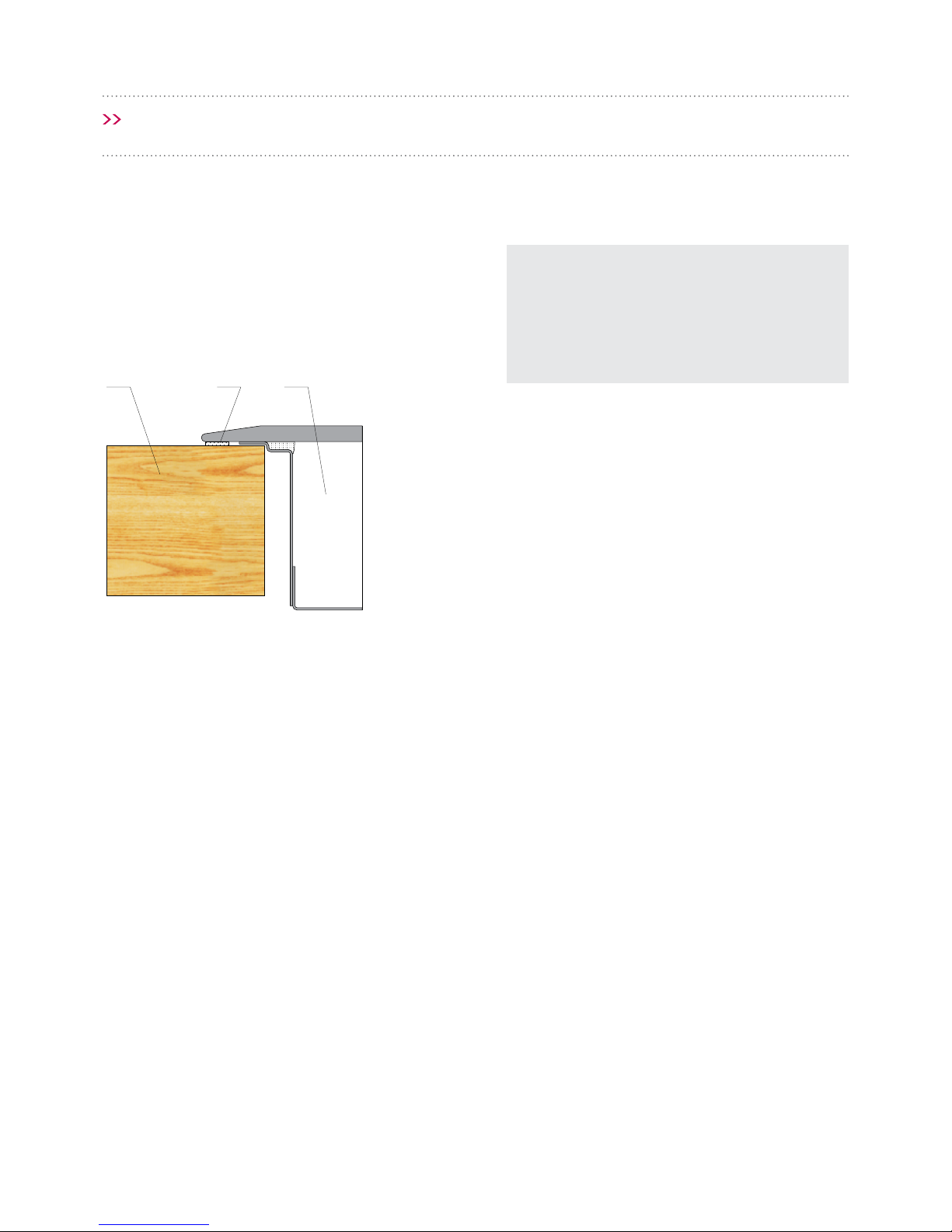
Figure 3.
1. Benchtop
2. Flange Gasket
3. Induction cooktop
Page 13

INSTALLATION
Page 13
TIPS FOR THE INSTALLER
The cooktop is equipped with a terminal block
allowing dierent connections appropriate for a
specic type of power supply.
Terminal block allows the following connections:
Single-phase 220-240 V ~
Two-phase 400 V 2N~
The cooktop can be adapted to a specic type
of power supply by bridging the appropriate
terminals according to wiring diagram. The wiring
diagram is placed on the cooktop’s underside. The
terminal block can be accessed by removing the
lid on cooktop’s underside. Remember to match
the power cord to the type of connection and the
cooktop’s power rating.
IMPORTANT
Remember to connect the Earth lead to the correct terminal block clamp, marked with . The electrical
system supplying the cooktop must be protected by a appropriate tripping device or a circuit breaker
allowing to disconnect the power supply in an emergency.
When connecting to xed wiring a means for an all pole disconnection with at least 3mm contact
separation must be incorporated in the xed wiring in accordance with the wiring rules. This appliance
should only be installed by qualied persons.
Before connecting the appliance to power, carefully
read the information provided on the rating plate
and wiring diagram.
Connecting the cooktop other than shown on
the wiring diagram will cause damage.
Page 14

INSTALLATION
Page 14
WIRING DIAGRAM
IMPORTANT: Heating elements operate at 220-240 V ~
Important! For each connection the protective conductor must be
connected to the terminal marked
.
Type / Conductor
cross section
Fuse protection
1 For a 230 V single phase
connection with a neutral lead,
terminals L1, L2 are bridged,
neutral lead is connected to
terminal N, and the protective
conductor to
.
1N~
NL1
HO5VV-FG
3 x 4mm
2
min.30A
2* For a 230/400 V two phase
connection with a neutral lead,
neutral lead is connected to
terminal N, and the protective
conductor to
.
2N~
NL1L2
HO5VV-FG
4 x 2.5mm
2
min.16A
L1 = R, L2 = S, L3 = T; N = neutral lead connection;
= protective lead terminal
* For domestic 3-phase 230/400 V electrical system, connect the remaining wire to the terminal:L3, which is not
connected to the cooktop internal electrical system.
* NN terminals are internally connected, they need not be bridged
Page 15

BEFORE USING THE APPLIANCE
FOR THE FIRST TIME
• Thoroughly clean your induction cooktop rst.
The induction cooktop should be treated with
the same care as a glass surface.
• Switch on the ventilation in the room or open
a window, as the appliance could emit odours
during rst use.
• Operate the cooktop observing all safety
guidelines.
INDUCTION COOKING OPERATION PRINCIPLE
An electric oscillator powers a coil placed inside
the appliance. This coil produces a magnetic eld,
which induces eddy currents in the cookware.
These eddy currents induced by the magnetic eld
cause the cookware to heat up.
This requires the use of pots and pans a
ferromagnetic base — in-other-words susceptible
to magnetic elds.
Overall, induction technology is characterised by
two advantages:
• The heat is only emitted by the cookware,
• There is no thermal inertia, since the cooking
starts immediately when the pot is placed on the
cooktop and ends once it is removed.
Certain sounds can be heard during normal use
of the induction cooktop, which do not aect its
correct operation.
Low-frequency humming. This noise arises when
the cookware is empty and stops when water is
poured or food is placed in the cookware.
• High-frequency whiz. This noise arises in
cookware made of multiple layers of dierent
materials at maximum heat setting. The noise
intensies when using two or more cooking
zones at maximum heat setting. The noise will
stop or reduce when the heat setting is reduced.
• Creaking noise. This noise arises in cookware
made of multiple layers of dierent materials.
The noise intensity depends on how the food is
cooked.
• Buzzing. Buzzing can be heard when the
electronic cooling fan operates.
The noises that can be heard during the normal
appliance operation are the result of the cooling
fan operation, cooking method, cookware
dimensions, cookware material and the heat
setting. These noises are normal and do not
indicate a fault.
Page 15
OPERATION
Page 16

OPERATION
Page 16
Protective device: If the cooktop has been
installed correctly and is used properly, any
protective devices are rarely required.
Fan: protects and cools controls and power
components. It can operate at two dierent speeds
and is activated automatically. Fan runs until the
electronic system has suciently cooled down
regardless of the appliance or the cooking zones
being turned on or o.
Temperature sensor: The temperature of the
electronic circuits is continuously monitored by
a temperature sensor. If temperature is raised
beyond a safe level, the protection system will
reduce the cooking zone heat setting or shut down
the cooking zones adjacent to the overheated
electronic circuits.
Pan detection: sensor allows the cooktop to
detect pans placed on a cooking zone. Small objects
placed on the cooking zone (eg, spoon, knife, ring,
etc.) will not be recognised as pans and the cooktop
will not operate.
PAN DETECTOR
A pan detector sensor is installed in this induction
cooktop. The pan detector starts heating
automatically when a pan is detected on a cooking
zone and stops heating when it is removed. This
helps save electricity.
When a suitable pan is placed on a cooking zone,
the display shows the heat setting.
IMPORTANT
If a pan is not placed on a cooking zone or
the pan is unsuitable, the symbol is
displayed. The cooking zone will not operate.
If a pan is not detected within 90 seconds,
the cooking zone will be switched o.
Switch o the cooking zone using the touch
control sensor eld rather than by removing
the pan.
Pan detector is not an on/o operation.
The induction cooktop is equipped with electronic
touch control sensor elds, which are operated by
touching the marked area with a nger.
Each time a sensor eld is touched, an acoustic
signal can be heard.
IMPORTANT
When switching the appliance on or o, or
changing the heat setting, touch only one sensor
eld at a time.
When two or more sensor elds are touched at
the same time, the appliance ignores the control
signals and may trigger a fault indication (with
the exception of Bridging, Timer, and Child Lock
operations).
When you nish cooking switch o the
cooking zone using the touch control sensor
elds and do not rely solely on the pan
detector.
Page 17
OPERATION
Page 17
COOKWARE CHARACTERISTICS
• To determine if cookware is suitable, make sure
that its base attracts a magnet.
• Always use high quality cookware, with perfectly
at base. This prevents the formation of local
hot spots, where food might stick. Pots and
pans with thick steel walls provide superior heat
distribution.
• Make sure that cookware base is dry: when
lling a pot or when using a pot taken out of the
refrigerator, make sure its base is completely dry
before placing it on the cooking zone. This is to
avoid soiling the surface of the cooktop.
• A lid prevents heat from escaping and
reduces heating time as well as lowers energy
consumption.
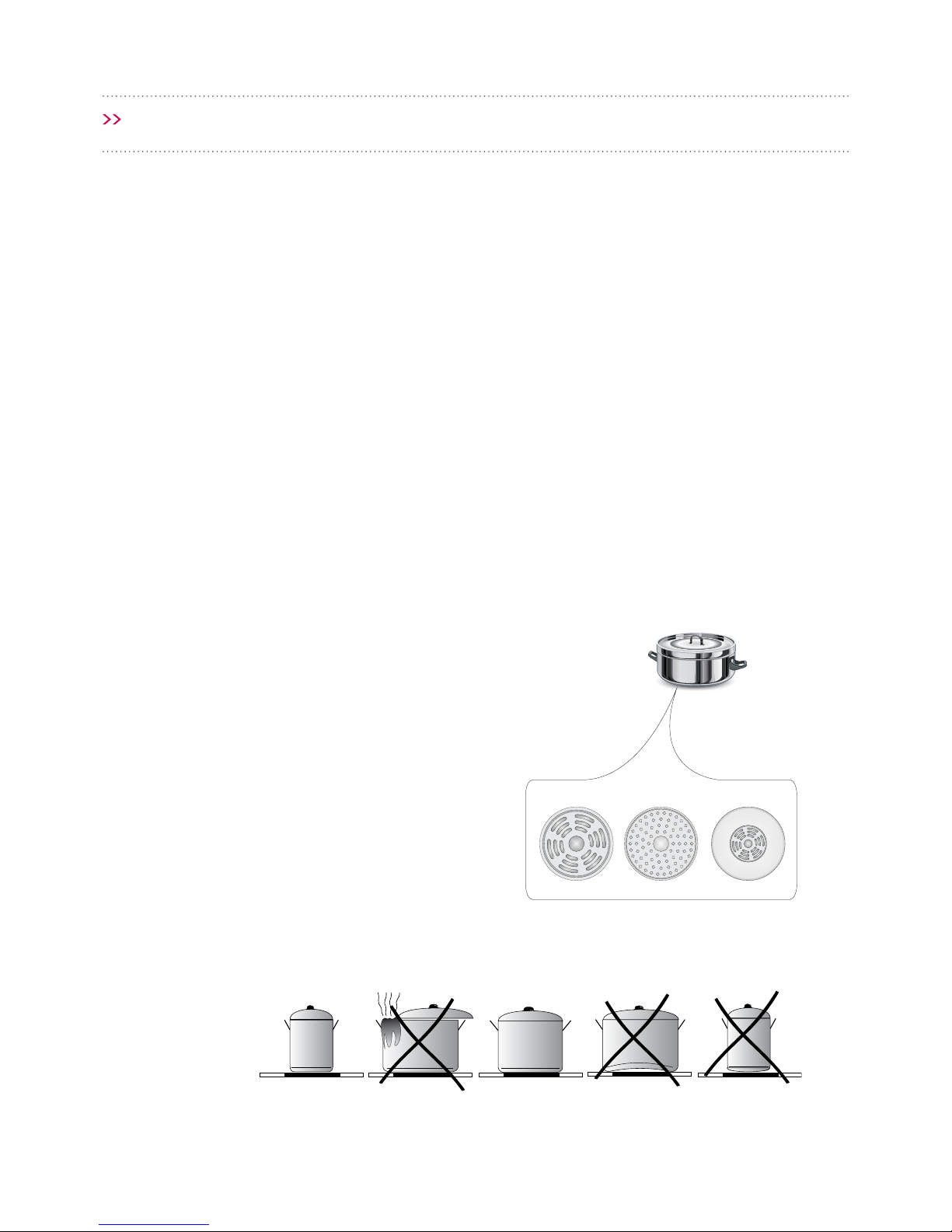
• Cookware base has to be at for optimal
temperature control by the induction
module.
• A concave base or deep-embossed
manufacturer’s logo (Fig. 1) may interfere
with the temperature induction control
module and can cause overheating of the
pot or pan.
• Do not use damaged cookware such as
cookware with a deformed base due to
excessive heat.
• Ensure cookware is placed on the cooking
zone correctly (Fig. 2).
• When you use large ferromagnetic base
cookware, whose diameter is less than the
total diameter of the cooking zone, only the
ferromagnetic base heats up. This results in a
situation where it is not possible to uniformly
distribute the heat in the cookware. If the
ferromagnetic area is reduced due to inclusion of
aluminium parts then the eective heated area
can be reduced. Problems with the detection of
the cookware could arise or cookware may not be
detected at all. To achieve optimum cooking
results, the diameter of the ferromagnetic
base should match that of the cooking
zone. If cookware is not detected in a given
cooking zone, it is advisable to try it in a smaller
cooking zone.
SELECTING COOKWARE TO USE WITH YOUR INDUCTION COOKTOP
High-quality cookware is essential for optimal induction cooking.
Figure 1.
Figure 2.
Page 18
OPERATION
Page 18
For induction cooking us only ferromagnetic base materials such as:
• Enamelled steel
• Cast iron
• Special stainless steel cookware designed for induction cooking.
How will I know my cookware
is suitable for use on the
induction cooktop?
Check for markings on the cookware indicating that the cookware is
suitable for induction cooking.
Use magnetic cookware (enamelled steel, ferrite stainless steel, cast iron).
The easiest way to determine if your cookware is suitable is to perform the
“magnet test”. Find a generic magnet and check if it sticks to the base of the
cookware.
About Stainless Steel
Cookware
Stainless steel cookware will not be detected; with the exception of the
ferromagnetic steel cookware.
Aluminium Cookware Aluminium cookware will not be detected.
Cast Iron Cookware
High eciency.
CAUTION: Cast Iron Cookware can scratch the cooktop surface.
Enamelled Steel Cookware High eciency.
Cookware with a at, thick and smooth base is recommended.
Glass Cookware Glass cookware will not be detected.
Porcelain Cookware Glass cookware will not be detected.
Cookware with copper base Glass cookware will not be detected.
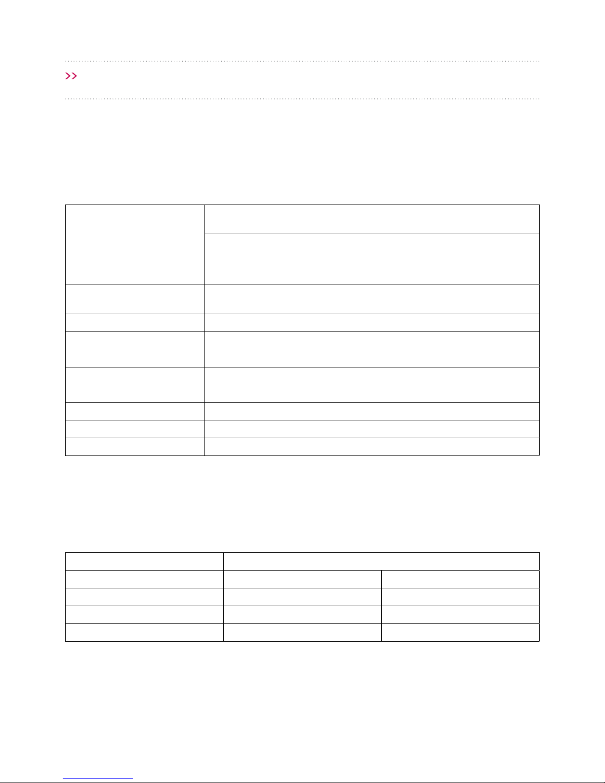
COOKWARE SIZE
• Energy is transferred best when cookware size corresponds to the size of the cooking zone. The smallest and
largest possible diameters are indicated in the following table and depend on the quality of the cookware
used.
• When using cookware smaller than the minimum diameter, the induction cooktop may not work.
Induction cooking zone The base diameter of induction cookware
Diameter (mm) Minimum (mm) Maximum (mm)
2 x 220 x 190 120 220
1 x 260 160 260
1 x 210 140 210
Page 19

OPERATION
Page 19
1
2
3
3
3
4
5
6
78
9
10
11
5
3
CONTROL PANEL
Immediately after the appliance is connected to
electrical mains, all displays will light up briey.
Your induction cooktop is then ready for use.
The induction cooktop is equipped with electronic
touch control sensor elds, which are operated by
touching with a nger for at least 1 second.
Touching the sensor eld is accompanied by an
acoustic signal to acknowledge.
No objects should be placed on
the sensor elds (this could cause
an error). Touch sensor elds
should always be kept clean.
If none of the sensor elds are
touched within 10 seconds of
switching on the appliance,
the cooking zone switches o.
A cooking zone is active when its
display shows a digit or a letter.
This indicates the cooking zone
is ready for the heat setting to be
set or changed.
If none of the sensor elds are
touched within 10 seconds, the
appliance switches itself o.
SWITCH ON THE APPLIANCE
• To switch on the appliance touch and hold the
on/o sensor eld (1) for at least 1 second.
• The appliance is switched on when all heat
setting displays (3) show “ ” and decimal point
is ashing.
SWITCH ON THE COOKING ZONE
Once the appliance is switched on using the on/o
touch sensor (1), select a cooking zone (3) within
the next 10 seconds.
1. When a cooking zone selection sensor eld (3) is
touched, “ ”on the corresponding heat setting
indicator display will pulsate.
2. To select the desired heat setting, slide your
nger across the setting selection sensor eld (2).
CONTROL PANEL
SENSOR FIELDS:
1. On/o sensor eld
2. Heat setting selection sensor eld
3. Cooking zone indicator
4. Timer display
5. Timer indicator light
6. Booster sensor eld
7. Stop ’n’ go function sensor eld
8. Keep Warm function sensor eld
9. Child lock sensor
10. Child lock indicator light
11. Kitchen timer indicator light
Page 20

OPERATION
Page 20
SELECTING THE COOKING ZONE HEAT
SETTING
When the cooking zone display (3) shows pulsating
“ ” start setting the desired heat setting by sliding
your nger across the setting selection sensor eld
(2).
DEACTIVATE COOKING ZONES
• A given cooking zone must be active. Heat
setting display pulsates.
• To switch o a cooking zone touch the on/
o sensor eld or touch the sensor (3) for
3 seconds. Slide your nger across the heat
selection sensor eld (2) to reduce the heat
setting to “ ”.
SWITCH OFF THE APPLIANCE
• The appliance operates when at least one
cooking zone is on.
• To switch o the appliance touch the on/o
sensor (1).
If a cooking zone is still hot, the relevant display (3)
will show the letter “ ” to indicate residual heat.
BOOSTER FUNCTION
“
”
The Booster Function increases the nominal power
of individual cooking zones from
ø 220 x 190mm cooking zone from 2200W to 3700W,
ø 260mm cooking zone from 2100W to 3400W,
ø 210mm cooking zone from 2000W to 3000W,
Bridge from 3600W to 5500W.
In order to activate the Booster function, select
the cooking zone and then using sensor (6) set the
heat setting to “ ”. The letter “ ” will be shown on
the display (3).
To switch o the Booster function, touch the heat
setting selection sensor eld (2) and reduce the
heat setting, or lift the pot from the cooking zone.
For Ø 220x190 cooking zone, operation
of the Booster function is limited to 10
minutes. Once the Booster function is
automatically deactivated, the cooking
zone continues to operate at its nominal
power.
The Booster function can be reactivated,
provided the appliance electronic
circuits and induction coils are not
overheated.
When the pot is lifted from the
cooking zone when the Booster function
is in operation, it remains active and the
countdown continues.
If the cooktop’s electronic circuits or
induction coils overheat when
the Booster function is in operation,
it is automatically deactivated. The
cooking zone then continues to operate
at its nominal power.
Page 21

OPERATION
Page 21
BOOSTER FUNCTION CONTROL
You can use booster function on two vertically or
horizontally arranged cooking zones at the same
time.
THE CHILD LOCK FUNCTION
The Child Lock function protects the appliance from
inadvertent operation by children. The appliance
can be operated once the child lock function has
been released.
The Child Lock function can be set when the
appliance is turned on or o.
TURN CHILD LOCK ON/OFF
Touch and hold sensor (9) for 5 seconds to turn
Child Lock on/o. Indicator light (10) is on when the
Child Lock function is on.
The Child Lock function remains set until
it is released even after the appliance
has been switched o and then
switched on again.
Disconnecting the appliance from the
electrical mains deactivates the Child Lock.
RESIDUAL HEAT INDICATOR
Heat energy that remains
accumulated in the cooking zone
after cooking is called the residual
heat. The appliance displays two
dierent levels of residual heat.
When a cooking zone temperature
is above 60°C and the cooking
zone or the appliance is switched o, the relevant
cooking zone display will show the letter “ ”.
Residual heat indication is displayed as long as the
cooking zone temperature exceeds 60°C. When a
cooking zone temperature is between 45°C and
60°C, the relevant cooking zone display will show
the letter “ ” indicating low residual heat. When
a cooking zone temperature is below 45°C the
residual heat indication is turned o.
When the residual heat indicator is on,
do not touch the cooking zone as there
is a risk of burns. Do not place any items
that are sensitive to heat on the zone.
The “ ” residual heat indicator is not
displayed during a power outage.
However, cooking zones may still be hot!
Page 22

OPERATION
Page 22
If a pot is lifted from the cooking zone
and replaced before the warm-up
countdown is completed, the warm-up
function will resume and countdown will
continue until completed.
LIMITING THE OPERATING TIME
In order to increase eciency, the induction
cooktop is tted with an operating time limiter for
each of the cooking zones. The maximum operating
time is set according to the last heat setting
selected.
If you do not change the heat setting for a long
time (see table) then the associated cooking zone
is automatically switched o and the residual heat
indicator is activated. However, you can switch on
and operate individual cooking zones at any time in
accordance with the operating instructions.
AUTOMATIC WARMUP FUNCTION
• Touch sensor eld (3) to activate the selected
cooking zone.
• Then sliding your nger across the setting
selection sensor eld (2) set the desired heat
setting in the 1-8 range and then touch sensor
eld (3) again.
• The display will alternate between the letter
“ ” and the heat setting.
After a certain time of operation at boosted power,
the cooking zone switches back to the heat setting
set, which will be shown on the display.
Cooking Heat Setting Maximum Operating
Time (hours)
8
1 8
2 8
3 5
4 5
5 5
6 1.5
7 1.5
8 1.5
9 1.5
P 0.16
Cooking Heat Setting Duration of the
Automatic Warm-up
(minutes)
1 0.8
2 1.2
3 2.3
4 3.5
5 4.4
6 7.2
7 2
8 3.2
Page 23

OPERATION
Page 23
SETTING THE TIMER
The timer function makes cooking easier by setting
the cooking duration. The timer function can only
be set when a cooking zone is operating (heat
setting is greater than “ ” ). The timer function
can be set independently for all individual cooking
zones. Timer countdown can be set from 1 to 99
minutes.
To set the timer:
• Select a cooking zone by touching cooking the
zone selection sensor eld (3) and select the
desired heat setting from 1 to 9 by sliding your
nger across the heat setting selection sensor
eld (2). The display will show the selected heat
settings from 1 to 9.
• Then, during the next 10 seconds, touch the
Timer selection sensor eld (4). “
” will
be shown on the Timer display (4) and the
appropriate Timer activation indicator light (5)
will light up to indicate activation of the Timer
function for the relevant cooking zone.
• Now, select the desired Timer setting by sliding
your nger across the setting selection sensor
eld (2). The second digit is set rst and the rst
digit is set next. Once the second digit is set,
touch the sensor (4) again to set the rst digit. If
you do not set any value for the rst digit within
10 seconds, the value will be set to “ ” (eg.
“
”). The countdown starts when the Timer
activation indicator light (5) starts ashing.
CHANGING TIMER DURATION
Programmed Timer setting can be changed at any
time.
To change the programmed Timer setting, select
a cooking zone by touching the cooking zone
selection sensor eld (3), and then touch the Timer
selection sensor eld (4).
CHECK TIMER DURATION
To check progress of Timer countdown at any time,
touch the timer sensor eld (4). Timer indicator
light (5) for the relevant cooking zone will ash.
STOP THE TIMER
When the set time has elapsed an acoustic signal
is sounded, which can be muted by touching any
sensor eld. If no sensor eld is touched, the
acoustic signal will stop automatically after 2
minutes.
To stop the timer countdown before the set
cooking duration has elapsed:
• Touch cooking zone selection sensor eld (3) to
select a cooking zone. The display will become
bright.
• Then touch and hold sensor eld (4) for 3
seconds or adjust duration using the sensor eld
(2) sliding your nger down to “
” .
Timer countdown can be set
independently for all cooking zones.
If more than one timer is set the shortest
duration is displayed. Timer indicator
light (5) of a relevant cooking zone will
ash.
Page 24

OPERATION
Page 24
KITCHEN TIMER
When no cooking zones are in use, the Timer
function can be used as a regular Kitchen Timer.
SET KITCHEN TIMER
When the appliance is o:
• Touch the on/o sensor (1) to turn on the
appliance. “ ” will be shown on cooking zone
displays (3).
• Then, during the next 10 seconds, touch the
Kitchen timer selection sensor eld (4). Kitchen
timer display (4) will show “
”.
• Now, select the desired Timer setting by sliding
your nger across the setting selection sensor
eld (2). The second digit is set rst and the rst
digit is set next. Once you set the second digit,
the appliance will automatically allow you to set
the rst digit. If you do not set any value for the
rst digit within 10 seconds, the value will be
set to “ ” (eg.“
”). The kitchen timer starts
countdown when the indicator lamp (11) starts
ashing.
STOP KITCHEN TIMER
When the set duration has elapsed an acoustic
intermittent signal is sounded (beeping), which
can be muted by touching any sensor eld. If no
sensor eld is touched, the acoustic signal will stop
automatically after 2 minutes.
To stop the timer countdown before the set
duration has elapsed:
• Touch and hold sensor eld (4) for 3 seconds or
adjust duration using the sensor eld (2) sliding
your nger down to “
”
• Kitchen Timer function does not aect cooking
zone operation.
Kitchen timer is reset when the timer
function is activated.
Page 25

OPERATION
Page 25
KEEP WARM FUNCTION
The Keep Warm function allows you to set any zone
to one of three preset ‘ideal’ cooking temperatures:
• 42°C - butter or chocolate melting; keeps readyto-serve food warm, retaining taste, and prevent
contents from sticking to the bottom of the pan .
• 70°C - reheating food to ready-to-serve
temperature
• 94°C - maintain rolling boil.
For the Keep Warm function to operate correctly,
use a at base pot or frying pan, so that the
base temperature is accurately measured by the
temperature sensor tted in the cooking zone.
The Keep Warm function can be activated for any
cooking zone.
To activate a Keep Warm function:
• 42°C: Touch sensor (3) to select the cooking
zone, then touch Keep Warm function sensor
eld (8) and the display will show the “ ” symbol
indicating the temperature of 42°C is selected.
• 70°C: Touch Keep Warm function sensor eld (8)
again and the second “ ” symbol will be shown
indicating the temperature of 70°C is selected.
• 94°C: Touch Keep Warm function sensor eld
(8) again and the third “ ” symbol will be shown
indicating the temperature of 94°C is selected.
To turn o the Keep Warm function:
• To turn o the Keep Warm function at any time
touch sensor (3), and then slide across the
sensor (2) to reduce heat setting to “ ” .
STOP ‘N’ GO FUNCTION
“
”
Stop ‘n’ go function acts like a ‘pause button’. It
simultaneously suspends operation of all cooking
zones and then resumes at the heat settings that
were previously set.
To activate the Stop ‘n’ go function:
In order to activate the Stop ‘n’ go function, at least
one cooking zone must be in use.
Next, touch the Stop ‘n’ go function sensor eld (7).
“ ” will be shown on all cooking zone displays (3).
When a cooking zone is still hot, the “ ” symbol will
alternate between “ ” and “ ” indicating residual
heat in a given cooking zone.
To activate the Stop ‘n’ go function:
To deactivate the Stop ‘n’ go function, touch the (7)
sensor eld again. The cooking zone displays (3)
will show the heat setting that was previously set
before activation of the Stop ‘n’ go function.
BRIDGE FUNCTION
The Bridge function allows pairing of two cooking
zones into a single combined cooking zone. The
Bridge function is very convenient, especially when
cooking with very large pots, grill skillets or baking
pans.
Note: The two left cooking zones can be bridged.
In order to activate the Bridge function, touch
the cooking zone sensor eld (3) and then
simultaneously touch two sensors of both left side
cooking zones (3). The rear cooking zone will display
“ ” , while the front cooking zone will display “ ” .
The desired heat setting is selected by sliding your
nger across the setting selection sensor eld (2).
Both cooking zones can now be controlled at
the same time.
In order to deactivate the Bridge function, touch
and hold the cooking zone sensor (3) with symbol
“
” for 3 seconds. The respective cooking zone
displays will show “ ” .
Both cooking zones can now be controlled
independently.
Page 26
Page 26
CLEANING AND MAINTENANCE
Proper routine maintenance and cleaning of the
appliance can signicantly extend its trouble-free
operation.
Cleaning After Each Use
Wipe light stains with a damp cloth without
detergent. The use of dishwashing liquid may
cause a bluish surface discolouration. These
persistent stains cannot always be removed right
away, even using a special cleaner.
Spills that have set hard can be carefully removed
with a scraper. Then wipe the cooking surface with
a damp cloth.
REMOVING STAINS
Bright stains of pearl colour (residual
aluminium) can be removed from the cool cooktop
using a special cleaning agent. Limestone residue
(eg. after evaporated water) can be removed by
vinegar or a special cleaning agent.
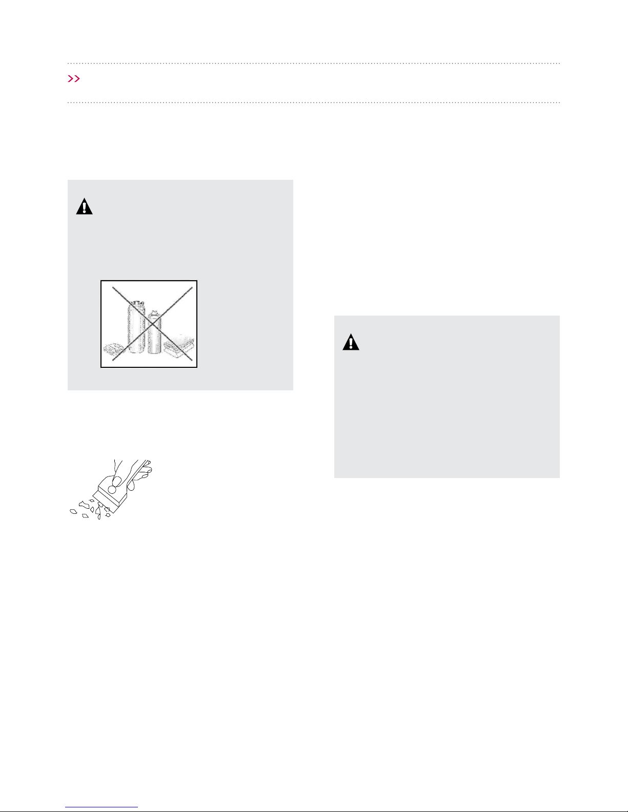
Turn o the cooking zone before removing sugar,
food containing sugar, plastic and aluminium foil.
Immediately and thoroughly scrape the leftovers
o the hot cooking zone using a sharp scraper.
Once the bulk of the stain is removed, the cooktop
can only be cleaned with water or an appropriate
specially designed cleaning agent*.
When cleaning your induction cooktop,
the same principles apply as for
glass surfaces. Do not use under any
circumstances any abrasive or caustic
cleaners or scouring powders or pads. Do
not use steam or pressure cleaners.
DO NOT use any descaling agents to
clean the cooktop.
Special cleaners designed especially for
induction cooktop surfaces are available in
supermarkets, electrical and home appliance
stores, and the Schweigen kitchen showroom.
Scrapers can be purchased in hardware
stores, as well as in shops carrying painting
accessories.
Page 27

CLEANING AND MAINTENANCE
Page 27
PERIODIC INSPECTIONS
In addition to normal cleaning and
maintenance:
• Carry out periodic checks of touch controls. After
the warranty expires, have an authorised service
technician inspect the appliance every two
years.
• Repair any identied problems.
• Carry out periodic maintenance of the cooktop.
IMPORTANT
All repairs and adjustments must be
performed by a qualied technician or by an
qualied installer.
Never apply a detergent on the hot cooking zone.
Any traces of the detergent should be wiped
o clean with a damp cloth before re-heating.
Otherwise, it can be corrosive.
Warranty will be void if you do not follow the
above guidelines!
IMPORTANT
If the cooktop controls do not respond for
whatever reason, turn o the main circuit
breaker or disconnect the power and contact
customer service.
In the event of breakage or chipping of the
cooktop cooking surface, turn o and unplug
the appliance. To do this, disconnect the
power or unplug the appliance. Then refer
the repair to Customer Service or a qualied
technician.
Page 28

Page 28
TROUBLESHOOTING
In the event of any fault:
• Turn o the appliance
• Disconnect the power supply
• Based on the instructions given in the table
below, some minor issues can be corrected by
the user. Please check the consecutive points in
the table before you refer the repair to customer
service or qualied technician.
Problem Possible Cause Remedy
1. The appliance does not
work
- No power - Check the power is connected
2. Sensor elds do not
respond when touched
- Appliance is not turned on - Turn on the appliance
- Sensor eld touched too briey
(less than one second)
- Touch the sensor eld longer
- Multiple sensors touched at the
same time
- Always touch only one sensor eld
(except when a cooking zone is
switched o)
3. The appliance does not
respond and emits and
extended beep
- Improper use (wrong sensor eld
touched or sensors touched too
briey)
- Reconnect the cooktop
- sensor elds are covered or dirty - Uncover or clean the sensor elds
4. The appliance switches
itself o
- No sensor eld is touched within 10
seconds of activating the appliance
- Switch on the appliance and set heat
setting without delay
- Sensor elds covered or dirty - Uncover or clean the sensor elds
5. A single cooking zone
switches o and residual
heat indicator “
” is shown.
- Limited cooking time - Switch on the cooking zone again
- Sensor elds covered or dirty - Uncover or clean the sensor elds
- Electronic components overheated
6. Residual heat indicator
extinguished even though
the cooking zones are hot
- A power outage or the appliance has
been disconnected from power
- Residual heat indicator will be shown
again the next time the appliance is
turned on and o again
Page 29

TROUBLESHOOTING
Page 29
Problem Possible Cause Remedy
7. The cooktop cooking
surface is cracked.
Danger! Immediately unplug the appliance or switch o the main
circuit breaker. Contact Customer Service or a qualied technician.
8. When the problem is still
not remedied.
Immediately unplug the appliance or switch o the main circuit breaker. Refer
the repair to Customer Service or a qualied technician.
IMPORTANT
You are responsible for operating the appliance correctly and maintaining
its good condition. If you call service as a result of operating the appliance
incorrectly you will be responsible for the costs incurred even under warranty.
The manufacturer shall not be held liable for damage caused by failure to follow
this manual.
9. Induction cooktop makes
buzzing sound.
This is normal. Cooling fan is operating to cool down internal electronics.
10. Induction cooktop
makes hissing and whistling
sounds.
This is normal. When using several cooking zones at full power, the cooktop makes
hissing and whistling sounds due to the frequencies used to power the coils.
11. The cooktop does not
work. The cooking zones will
not operate.
- Faulty electronics - Reset the appliance, unplug it for a
60 seconds (disconnect the power).
Page 30

770mm
518mm
Page 30
SPECIFICATION
Rated voltage 400V 2N~50 Hz
Rated power 7.4kW
Model INID77
Induction cooking zone:
- Ø 220 x 190mm
- Ø 210mm
- Ø 260mm
- Ø 210mm
- Ø 260mm
2200W
2000W
2100W
2000/3000W
2100/3400W
Booster induction cooking zone:
- Ø 220 x 190mm
- Ø 210mm
- Ø 260mm
2200/3700W
2000/3000W
2100/3400W
Dimensions 770 x 518 x 59mm
Weight 15kg
Page 31

Page 31
NOTES
Page 32

© Schweigen Home Appliances Pty Ltd. 2017.
8/3-4 Anzed Court, Mulgrave, Victoria 3170.
Phone: 1300 881 693.
Email: sales@schweigen.com.au.
www.schweigen.com.au
© Schweigen Pty Ltd. 2017.
 Loading...