

Page 1
Page 1Page 1
INSTRUCTION MANUAL
.........................................................................................................................................................
Installation / Operation / Maintenance
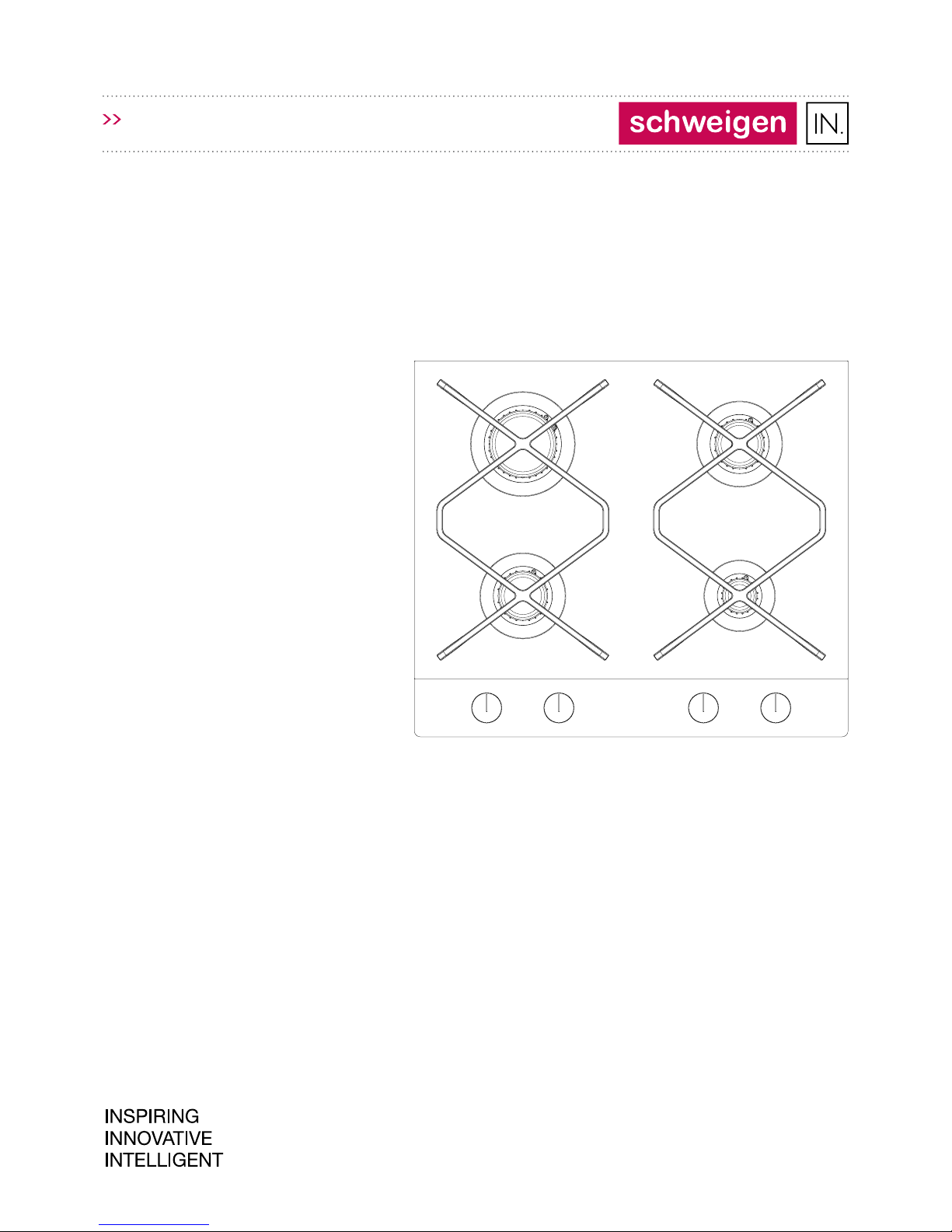
cooktop/GAS/glass/60cm
INGG60B
GAS COOKTOP
INGG60B (PGINGp4.0ZpZtAB)
(10.2017 / V2.0)
Page 2

Page 2
INDEX
Page 2
Welcome ��������������������������������������������������������� 3
Important Safety Information ���������������������� 4
How to Save Energy ��������������������������������������� 6
Unpacking ������������������������������������������������������� 6
Disposal of the Appliance ������������������������������ 7
Description of the Appliance ������������������������ 8
Control Panel ............................................................... 8
Specication �������������������������������������������������� 8
Installation ����������������������������������������������� 9-16
Ventilation .................................................................... 9
Combustible Surfaces ................................................ 9
Requirements for the Placement of Installation ... 9
Minimum Clearance Measurements ...................... 10
Notes for the Installer .............................................. 11
Gas Connection ......................................................... 12
Universal Gas - ULPG ............................................... 12
Natural Gas ................................................................ 12
Installing the Gas Cooktop ...................................... 14
Adapt the Cooktop to a Particular Type of Gas .... 15
Table of Burner & Injector Characteristics ........... 15
Adjust the Valves for a Reduced Flow .................. 15
Adjust the Valves ..................................................... 16
Glass Top Safety Warnings ..................................... 16
Operation ������������������������������������������������� 17-18
Energy Eciency ...................................................... 17
Choice of Cookware .................................................. 17
Cookware Lids ............................................................ 17
Burner Control Dial .................................................... 17
Adjust Flame ............................................................. 18
Cleaning and Maintenance ��������������������������� 19
Burners, Trivets .......................................................... 19
Regular Inspections .................................................. 19
Service Request ........................................................ 20
Faulty Installation ..................................................... 20
In the Event of A Gas Leak Or Suspect Fault ��� 21
Troubleshooting ������������������������������������������� 22
Emergency Procedure ............................................. 23
Disclaimer .................................................................. 23
Page 3

Page 3
WELCOME
Page 3
Thank you for purchasing this Schweigen IN
appliance.
To achieve the optimal performance from your
appliance, and to avoid the risk of accident or
damage, it is essential to read this manual before
installation and rst time use.
This guide contains important information on the
use and maintenance of the appliance, as well as
important safety notes.
Your appliance has been thoroughly checked for
safety and functionality before being packaged
and leaving the manufacturer.
Please keep this instruction manual in a safe
place so you can refer to it at any time�
IMPORTANT!
The appliance should only be operated when
you have read and understood this manual
thoroughly.
The appliance can be only used for the purpose
for which it was designed. Any other use is
improper and can be dangerous.
Installation, regulation and maintenance
of gas and electrical appliances should only
be carried out by qualied and authorised
professionals familiar with Australian
Appliance Industry regulations.
Upon collection or delivery of the appliance,
any damage or defects must be reported
within 48 hours to your retailer or
Schweigen Customer Service, in order
to recognise any claim.
The manufacturer reserves the right to
introduce changes, which do not aect the
operation of the appliance, at any time.
Page 4

Page 4Page 4
The appliance and its accessible parts become hot
during use. Care should be taken to avoid touching
heating elements.
This appliance is not intended for use by anyone
(including children) with reduced physical, sensory
or mental capabilities, or lack of experience and
knowledge, unless they are supervised and/or have
been given instruction for use of the appliance.
Cleaning and user maintenance cannot be
performed by children without supervision.
Children should be supervised to ensure that they
do not play with the appliance.
• Unattended cooking on a cooktop with fat or oil
can be dangerous and may result in re.
• NEVER attempt to extinguish re with water.
Unplug the appliance and cover ame with lid or
non-combustible re blanket.
• DO NOT store anything on the cooking surface.
The appliance is not intended to be operated by
means of an external timer or separate remotecontrol system.
• DO NOT use steam cleaning equipment to clean
the cooktop or its parts.
• DO NOT USE OR STORE FLAMMABLE MATERIALS
IN OR NEAR THIS APPLIANCE.
• DO NOT SPRAY AEROSOLS IN THE VICINITY OF
THIS APPLIANCE WHILE IT IS IN OPERATION.
• DO NOT MODIFY THIS APPLIANCE.
• DO NOT PLACE ARTICLES ON OR AGAINST THIS
APPLIANCE.
• WHERE THIS APPLIANCE IS INSTALLED IN
MARINE CRAFT OR IN CARAVANS, IT SHALL NOT
BE USED AS A SPACE HEATER.
• Not suitable for use with aftermarket lids or
covers.
• DO NOT place anything, e.g. ame tamer or
griddle plate between pan and pan support.
• DO NOT remove the pan support and enclose
the burner with a wok stand.
• DO NOT use large pots or heavy weights which
can bend the pan support or deect ame onto
the hotplate. Locate pan centrally over the
burner so that it is stable and does not overhang
the appliance.
This appliance must be installed in accordance
with the applicable regulations and used only
in a well-ventilated room� Before you install
and use the appliance, carefully read the
operating instructions�
• DO NOT let children play with the appliance - hot
burners, trivet, pots with hot liquids may cause
burns.
• Make sure that the power cords of other equipment
do not touch any hot surfaces of the appliance.
• The power cord wall plug must be accessible after
appliance has been installed.
• DO NOT install the appliance near any cooling
equipment such as an air conditioning unit.
• DO NOT leave the appliance unattended while
cooking. Oils and fats may catch re due to
overheating.
• Make sure that liquids do not boil over onto the
burners.
• DO NOT open the valve on the gas connection or
the valve on the gas cylinder before you make sure
that all valves are closed.
• DO NOT allow liquids to boil over onto the burners
and avoid burner contamination. Soiled burners
must be cleaned & dried immediately after cooling.
• DO NOT place pots directly on the burners.
• DO NOT place pots weighing more than 5kg on
the trivet over one burner or more than 25kg on
the entire trivet. Do not place one pot on two
burners.
• DO NOT hit the control dials or burners.
• Persons without proper qualications and training
must not make any alterations or repair the
appliance.
• DO NOT extinguish the ame by blowing.
• DO NOT alter the appliance to allow it to be used
with a dierent type of gas, or move the appliance
to another place nor make any modications in the
gas supply system. These must be carried out by a
qualied installer only.
• DO NOT allow young persons who have not read
the operating instructions to use the appliance.
IMPORTANT SAFETY INFORMATION
Page 5
Page 5Page 5
• IF YOU SUSPECT A GAS LEAK, DO NOT:
light matches, smoke, turn on or o any electrical
devices (door bell, light switch, etc.) and use
other electrical or mechanical equipment that
can produce an electrical spark or impact spark.
In such a case, immediately close the valve on
the gas cylinder or the gas system shut-o valve,
ventilate the room and call a qualied person to
remove the cause of the leak.
• In the event of any technical fault, immediately
unplug the appliance (following the above rule)
and report the fault to the service centre or
qualied gas technician to be repaired.
• DO NOT connect any antenna cables, e.g. radio
receivers to the gas system
• In the event of ignition of gas escaping from a
leaking system, immediately shut o the gas
supply using the shut-o valve.
• In the event of ignition of gas escaping from
a leaking gas cylinder valve: cover the cylinder
with a wet blanket to cool it and close the valve
on the cylinder. Once cooled, move the gas
cylinder out to the open air. Do not reuse the
damaged gas cylinder. This procedure should be
carried out by a qualied gas technician.
• If you do not use the appliance for a few days,
close the gas system main valve, and after each
use in case of a gas cylinder.
CAUTION!
If the power cord is damaged, it must be
replaced by the manufacturer, its service
agent or a qualied person in order to
avoid a hazard.
Cooking with this appliance results in the emission
of heat and moisture in the room in which it is
installed. Make sure that kitchen is well ventilated.
Natural ventilation openings or forced mechanical
ventilation (rangehood) should be available.
• Prolonged intensive use of the appliance may
require additional ventilation, for example,
opening a window or a more eective
ventilation, such as increasing eciency of
mechanical ventilation rangehood, if applicable.
GAS & ELECTRICAL CONNECTION
This appliance must be installed only by authorised
persons and in accordance with this instruction
manual, AS/NZS 5601 — Gas Installations
(installations and pipe sizing), local gas tting
regulations, local electrical regulations, local water
regulations, local health regulations, Building Code
of Australia and any other government authority.
WARNING: This appliance must be earthed.
VENTILATION
The use of a gas cooking appliance results in the
production of heat and moisture in the room in
which it is installed. Ensure that the kitchen is well
ventilated; keep natural ventilation holes open or
install a mechanical ventilation device (mechanical
extractor hood). Prolonged intensive use of the
appliance may call for additional ventilation, e.g.
opening of a window or, more eective ventilation,
increasing the level of mechanical ventilation
where present.
IMPORTANT SAFETY INFORMATION
Page 6

Page 6Page 6
Using energy responsibly not only saves money but
also helps the environment. So let’s save energy!
And this is how you can do it:
• Use quality pans for cooking� Pans with thick,
at bases can save up to 1/3 on electric energy.
Remember to cover pans if possible, otherwise
you will use four times as much energy!
• Match the size of the saucepan to the
surface of the heating zone� Cookware base
should never be smaller than cooking zone.
• Ensure that heating zones and pan bases
are clean� Dirt can prevent heat transfer, and
repeatedly burnt-on spillages can often only be
removed by products which cause damage to the
environment.
• Do not uncover the pan too often
(a watched pot never boils!)
• Turn o the appliance in time and use the
residual heat� For long cooking times, turn o
heating zones 5 to 10 minutes before nishing
cooking. This saves up to 20% on energy.
• Do not install the cooktop in the immediate
vicinity of refrigerator / freezer, otherwise
energy consumption increases unnecessarily.
The appliance was packed to protected it from
damage during transport. After unpacking, please
dispose of all elements of packaging in a way that
will not cause damage to the environment.
All materials used for packaging the appliance are
environmentally friendly; they are 100% recyclable
and are marked with the appropriate symbol.
Important! During unpacking, keep the packaging
material (polyethylene bags, polystyrene pieces,
etc.) out of reach of children.
HOW TO SAVE ENERGY UNPACKING
Page 7

Page 7Page 7
This appliance is marked with the symbol of the
crossed-out waste container.
This marking indicates that the appliance must
not be disposed of together with other household
waste after it has been used.
The user is obliged to hand it over to waste
collection centre collecting used electrical and
electronic goods. The collectors, including local
collection points, shops and local authority
departments provide recycling schemes.
Proper handling of used electrical and electronic
goods helps avoid environmental and health
hazards resulting from the presence of dangerous
components and the inappropriate storage and
processing of such goods.
DISPOSAL OF THE APPLIANCE
Page 8
Page 8Page 8
....................................................................................................................................................
....................................................................................................................................................
>>
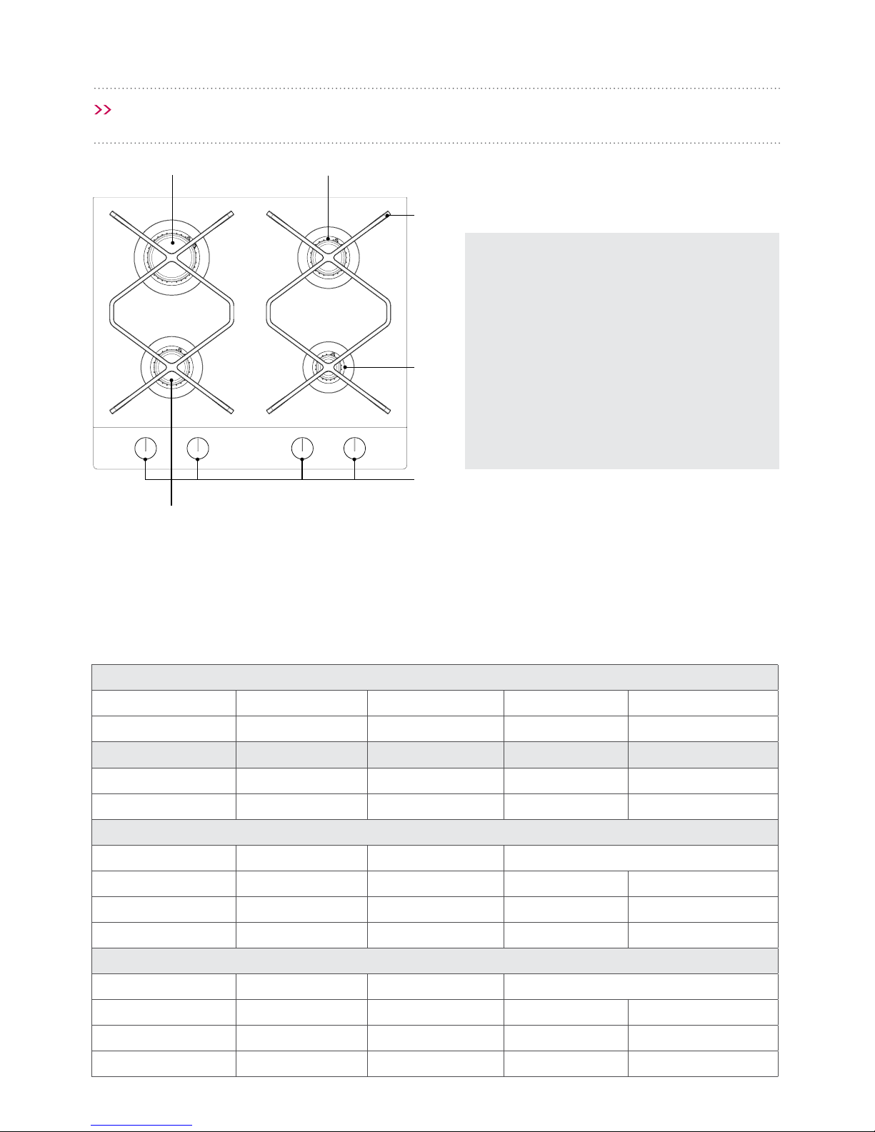
SPECIFICATION
LEGEND
AUX - Auxiliary Burner
SR - Semi-Rapid Burner
R - Rapid Burner
1 – Control Dials with incorporated
auto-ignition
2 – Trivets (cast iron pan supports)
DESCRIPTION OF THE APPLIANCE
Packaged Weight - 12kg
Overall Dimensions - 48mm (H) x 520mm (D) x 600mm (W)
Total Nominal Gas Consumption
Model Natural Gas Universal LPG
4 Burner INGG60B 30.8 MJ/h 30.2 MJ/h
Test Point Pressure
Natural Gas 1.0 kPa
Universal LPG 2.75 kPa
Burner Conguration - Natural Gas
Burner Main Injector By-Pass (mm) Nominal Gas Consumption (MJ/h)
Auxiliary 0.85 0.29 3.8
Semi-Rapid 1.20 0.29 7.7
Rapid 1.48 0.39 11.6
Burner Conguration - Universal LPG
Burner Main Injector By-Pass (mm) Nominal Gas Consumption (MJ/h)
Auxiliary 0.55 0.29 3.8
Semi-Rapid 0.79 0.29 7.6
Rapid 0.93 0.39 11.2
3
4
1 2
6
5
AUX
R
2
1
SR
SR
Page 9

Page 9Page 9
The following instructions are intended for a
qualied professional installer. These instructions
are intended to provide the most professional
installation and maintenance of the appliance.
• Before you install the appliance, make sure
that the local distribution conditions (gas
type and pressure) and conguration is
appropriate.
• Conguration details are given on the
appliance nameplate.
• This appliance is not to be connected to
ues. The appliance must be installed and
connected in accordance with the current
regulations. In particular, consideration
must be given to the applicable
requirements for ventilation.
REGULATIONS AND STANDARDS
This appliance must be installed by an authorised
persons in accordance with this instruction manual,
AS/NZS 5601 — Gas Installations (installation and
pipe sizing), local gas tting regulations, local
electrical regulations, local water regulations, local
health regulations, Building Code of Australia and
any other government authority.
• MUST NOT be installed in a marine craft,
caravan or mobile home, unless each
burner is tted with a ame safeguard.
VENTILATION
Ventilation must be in accordance with AS/NZS
5601 - Gas Installations. In general, the appliance
should have adequate ventilation for complete
combustion of gas, proper ueing and to maintain
temperature of immediate surroundings within
safe limits.
COMBUSTIBLE SURFACES
The wall and benchtop surfaces must be capable
of sustaining temperature of 90˚C. All laminates,
xing adhesive and surfacing materials should be
certied suitable for this temperature.
Requirements for the placement
of installation
• The kitchen should be dry, airy and well
ventilated according to the applicable technical
regulations.
• The room should be equipped with a ventilation
system to extract the combustion gases outside
the room. The ventilation system must include a
ventilation grille or a rangehood.
• The room should also allow air supply which is
necessary for the correct combustion of gas.
The air supply should be not less than 2 m³/h
per 1 kW of the burners power. Natural airow
from the outside may be provided or through a
duct with a cross-section of at least 100 cm²,
or indirectly from the adjacent rooms that have
ventilation ducts leading outside.
• The distance between the burners and the
rangehood exhaust should be at least 600 mm.
• The rangehood must be installed in accordance
with your rangehood installation guide, as
compliance with state and federal laws.
INSTALLATION
Page 10

Page 10
INSTALLATION
Page 10
MINIMUM CLEARANCE MEASUREMENTS
A� OVERHEAD CLEARANCE — (Measurement A)
Rangehoods and exhaust fans must be installed
in accordance with the manufacturer’s relevant
instructions.
However, in no case should the clearance
between the highest part of the hob of the
gas cooking appliance and a rangehood be less
than 600mm or, for an overhead exhaust fan,
750mm.
B & C� SIDE CLEARANCE
— (Measurements B & C) Where B, measured
from the periphery of the nearest burner to
any vertical combustible surface, or vertical
combustible surface covered with toughened
glass or sheet metal, is less than 200mm,
the surface shall be protected to a height C of
not less than 150mm above the hob for the
full dimension (width or depth) of the cooking
surface area.
Where the gas cooking appliance is tted with
a ‘splashback’, protection of the rear wall is not
required.
C
B
A
Page 11

Page 11
INSTALLATION
Page 11
This appliance shall be installed only by authorised
persons and in accordance with the manufacturer’s
installation instructions, local gas tting
regulations, municipal building codes, electrical
wiring regulations, local water supply regulations,
AS 5601 - Gas Installations and any other statutory
regulations.
NOTES FOR THE INSTALLER
The installer must:
- Have appropriate qualication,
- Read the information on the nameplate or
information sticker concerning the type of
gas, for which the appliance is intended.
This information must be compared with
the gas supply specication at the place of
installation.
Check:
- eectiveness of ventilation, i.e. exchange of
air in the room,
- tightness of gas ttings,
- proper operation all the functional
components.
For proper operation of igniters and ame failure
cut-o device, adjust the position of the gas dials
with the supplied washers.
- Check the operation of igniters and ame
failure cut-o device.
- In the event of faulty operation, remove the
dials, make adjustments by inserting a washer
(washers) on the valve pin.
- Once adjusted, protect the system with a
clamping washer and replace the cooktop.
PROVIDE THE USER WITH THE GAS COOKTOP
INSTALLATION CERTIFICATE AND GIVE
INSTRUCTIONS ON THE APPLIANCE OPERATION.
The appliance has an G 1/2” threaded pipe
connector to connect it to the gas system.
The gas supply hose should not touch the metal
parts of the cooktop.
Carefully read the operating instructions
supplied and follow all guidelines�
CAUTION!
Only a qualied person must install and
connect the appliance.
CAUTION!
Ensure all the connections are tight�
Once you install the appliance, check all
connections for leaks, for example using
soapy water. DO NOT use re to check
the connections.
IMPORTANT: You are dealing with
gas. The appliance must be supplied
with the type of gas specied by the
manufacturer.
Information on the type of gas for which
the appliance is designed is given on the
nameplate, which can be located on the
base of the cooktop.
Page 12

Page 12
INSTALLATION
Page 12
GAS CONNECTION
To perform these operations the qualied installer
will follow the indications given in the “Adaptation
to the various types of gas” section (see pg. 15). For
safer operation make sure that the supply pressure
respects the values given in the “Table of burner
and injector characteristics” (see pg. 15).
The appliance must be connected to the gas supply
or the cylinder according to the specications of
the standards and after checking that it is adjusted
for the type of gas available.
The gas connection is male 1/2” BSP and is
situated 55mm from the right and 565mm from
the oor. There are two ways to carry out the
connection to the main gas line:
A. The cooktop can be connected with rigid pipe
as specied in AS5601 - table 3.1.
B. The cooktop can be connected with a Flexible
Hose, which complies with AS/NZS 1869 (AGA
Approved), 10mm ID, class B or D, no more than
1.2m long and in accordance with AS5601.
Ensure that the Hose does not contact the
hot or sharp surfaces of the hotplate, oven,
dishwasher or other appliance that may be
installed underneath or next to the cooktop.
The isolating manual shut-o valve
connection point must be accessible when
the appliance is installed�
WARNING: Ensure that the hose assembly is
restrained from accidental contact with a ue
or ue outlet of an underbench oven. The gas
hose should not be subjected to abrasion, kinking
or permanent deformation and should be able
to be inspected along its entire length. Unions
compatible with the hose ttings must be used
and connections tested for gas leaks. The supply
connection point shall be accessible with the
appliance installed.
The appliance is factory set for Natural Gas. The
test point pressure should be adjusted to 1.00kPa
with 50% of the burners burners operating at
maximum.
The appliance is set up to operate with the gas
specied on the gas type label placed on the back
of the appliance.
When the type of gas available does not
correspond to that for which the appliance is set
up, replace the corresponding injectors (provided),
being careful to put on the new label (provided)
and remove the old one.
UNIVERSAL GAS - ULPG
When converting from Natural Gas to Universal
LPG ensure that the NG regulator is removed
and replaced with the Test Point Assembly. An
AGA Approved gas regulator suitable for a supply
pressure of 2.75kPa should be part of the gas
tank supply and the test point pressure should be
adjusted to 2.75kPa.
Before Leaving - Gas leakage and operation of the
appliance must be tested by the installer before
leaving. Check burner ames are blue in colour,
stable and completely ignite at both high and low
ame setings with no appreciable yellow tipping,
carbon deposition, lifting, oating, lighting back
or objectionable odour. Test burners individually
and in combination. When satised with the
operation of the cooker, please instruct the user
on the correct method of the operation in case
the appliance fails to operate correctly after all
checks have been carried out, call the Schweigen
Customer Service Team.
NATURAL GAS
Natural Gas installation requires the connection
of a gas regulator. Only use the Natural Gas
regulator supplied with this appliance. Assemble
the regulator (noting the gas ow direction) and
transition pieces (supplied with the appliance),
in accordance with Figure 1 below. The transition
piece on the supply side of the regulator must be
provided by the installer. The appliance has been
tted with injectors for natural gas. Universal ULPG
gas injectors (if required) have been included with
the cooktop. Gas pressure must be adjusted to
1.0kPa when approximately 50% of the burners
are on high ame, the appliance test point is
located on the regulator.
Test point
Fig� 1
Page 13

Page 13
INSTALLATION
Page 13
Cooktop installation must be in accordance
with state and federal laws�
When installing the cooktop in the kitchen
benchtop, install a partition panel, (see Fig.2A).
If the cooktop is to be installed above a built-in
oven, installation of the partition panel is not
required (see Fig. 2B).
If the cooktop is installed in the kitchen benchtop
above a drawer, the bottom cover of the cooktop
must be covered with a wooden panel or protective
board, provided it is capable of withstanding the
appliance temperature.
The rear edge of the cooktop opening should be
located at least 60 mm from the rear kitchen wall.
Min. 130mm
Fig� 2A Installation above a drawer
130mm
Oven
Cooktop
Fig� 2B Installation above an oven
WARNING!
DO NOT x the cooktop into the
benchtop with sealant, ie. sillicon, as this
will void the warranty.
IMPORTANT: DO NOT install the
cooktop above the oven without
ventilation; inadequate ventilation will
damage the cooktop and void warranty.
Position electrical lead so that it does
not touch the lower guard.
NOTE: Where the data plate is obstructed by
cabinetry when the cooktop is in the installed
position, attach the supplied dupolicate data
plate to a suitable adjacent surface or within the
instruction manual for future reference.
Page 14

Page 14
INSTALLATION
Page 14
4
321
4
321
555
484
01
32
170
170
170
30 30
135
30
20
242
600
520
84
INSTALLING THE GAS COOKTOP
1. Prepare an opening in the kitchen benchtop, as
per the installation measurements (see Fig. 3)
2. Ensure a minimum clearance of 130 mm below
the gas or gas-electric cooktop (see Fig. 2B on
previous page).
3. Connect the cooktop to a gas and electrical
system in accordance with the instructions
supplied.
4. Loosely attach xing brackets to the bottom of
the cooktop (see Fig. 4A and 4B).
5. To properly secure the cooktop on 38mm thick
benchtops use four xing brackets (see Fig. 4A)
6. To properly secure the cooktop on 28mm thick
benchtops use four xing brackets (see Fig.4B).
7. Fit the cooktop into the benchtop opening.
8. Check the adhesive seal is properly applied to
the under side of the cooktop ange.
9. Remove dust from the benchtop, insert cooktop
into the opening and press in rmly.
10. Position xing brackets (see Fig. 4)
perpendicular to the cooktop edge and tighten
rmly.
11. Once you install the cooktop in the benchtop,
check if it operates, especially the ame failure
cut-o and igniter.
Fig� 4
Fig� 4A
Fig� 4B
Fig� 3
1. Benchtop
2. Screw
3. Bracket
4. Cooktop
Page 15

Page 15
INSTALLATION
Page 15
TABLE OF BURNER & INJECTOR CHARACTERISTICS�
Type of gas
BURNER
Auxiliary Semi-Rapid Rapid
Natural Gas 0.85 1.20 1.48
ULPG 0.55 0.79 0.93
REPLACE BURNER NOZZLE
Unscrew the nozzle using a special wrench no. 7 and replace with a new one suitable
for the new gas type (see table above).
Once converted, place a sticker indicating the gas type for which the appliance
is intended. Replacing the burner nozzle is only to be carried out by a licensed,
qualied technician.
ADJUST THE VALVES FOR A REDUCED FLOW�
Burners Flame Convert the appliance from
LPG to Natural Gas
Convert the appliance from
Natural Gas to LPG
TOP BURNERS
Full ame Replace burner nozzle with the
appropriate nozzle according to
the table.
Replace burner nozzle with the
appropriate nozzle according to
the table.
Economic ame Gently loosen the adjusting screw
and adjust the ame.
Slightly tighten the adjusting
screw, check the ame stability
and size.
ADAPT THE COOKTOP TO A PARTICULAR
TYPE OF GAS
If the cooktop is set up with a gas type dierent
to the gas type specied by the manufacturer, i.e.
natural gas, replace the burner nozzles and adjust
the ame.
CAUTION
Cooktops supplied by the manufacturer are tted
with burners designed for the gas specied on the
nameplate and in the warranty.
Nameplate is located on the bottom of the housing
and lists information on the type of gas the
appliance is intended for.
In order to adapt the cooktop to another gas type:
- replace the nozzles (see table),
- adjust the valves for a reduced ow.
NOTE� This cooktop is for use with Natural Gas or
ULPG only.
Any other type of gas connection will void warranty
and the manufacturer will take no responsibility for
damages or accidents that may occur.
Page 16

ADJUST THE VALVES
To adjust the valves turn the control dial to
“economic ame” position and ignite the ame.
Remove the control dial and adjust the size of an
economic ame with a screwdriver.
In order to check the ame, heat up the burner on
a full ame for about 10 minutes, and then turn
the burner dial to an economic ame position. The
ame should not go out or jump on the nozzle.
However, if it does, re-adjust the valves.
WARNINGS FOR THE SAFETY OF
THE GLASS TOP
DO NOT place anything, e.g. ame tamer, asbestos
mat, between pan and pan suport, as serious
damage to the appliance may result.
DO NOT remove the pan support and enclose the
burner with a wok stand as this will concentrate
and deect heat onto the hotplate.
DO NOT use large pots or heavy weights which
can bend the pan support or deect ame onto the
hotplate.
Page 16
INSTALLATION
Page 16
Page 17

Page 17
OPERATION
Page 17
ENERGY EFFICIENCY
To achieve signicant energy savings, use the
appliance as per these operating instructions, make
the appropriate adjustments and use suitable pots.
Potential energy savings:
• up to 60%, when using appropriate pots,
• up to 60%, when using the appliance according
to the instructions and correctly adjusting the
ame when cooking.
Keeping the burners clean is crucial to an ecient
energy consumption by the appliance (especially
the ame outlets and nozzles).
CHOICE OF COOKWARE
Make sure that the diameter of the bottom of the
pot is always slightly larger than the crown of the
burner ame, and the pot itself is covered with
a lid. It is recommended that the pot diameter is
approximately 2.5 - 3 times larger than the burner:
• Auxiliary (Small) burner
— pot diameter of 90 to 150 mm,
• Semi Rapid (Medium) burner
— pot diameter of 160 to 220 mm,
• Rapid (Large) burner
— pot diameter of 220 to 240 mm
Note: The pot height should NOT be greater than
its diameter.
wrong
right
COOKWARE LIDS
Placing a lid on top prevents heat from escaping
and thus reduces heating time.
Do not use cookware that protrudes over
the edges of the cooktop.
BURNER CONTROL DIAL
"burner off" position
sition
position
CORRECT
INCORRECT
Page 18

Page 18
OPERATION
Page 18
Using the cooktop equipped with igniter dials
• push down the dial of a selected burner until
you feel resistance and turn left to the “large
ame”position
• hold the dial until gas ignites
• once ame ignites, release the dial and adjust
ame size.
The cooktop is equipped with a ame failure
cut-o device
In cooktops equipped with a ame-failure cut-o
device, hold the pushed down dial in the “large
ame” position for approximately 10 seconds to
activate the ame-failure device .
Repeat the above step if ame does
not ignite�
If ame is extinguished, the ame
failure device will cut o gas supply
within about 60 seconds�
You can open and control the gas
supply to the burners using dials with
ame-failure cut-o device�
ADJUST FLAME
Flame from a properly adjusted burner is pale blue
with a clearly outlined inner cone. You can adjust
the ame by setting the dial to dierent positions.
large ame
small ame (“economic”)
• burner o (no gas supply)
INCORRECT CORRECT
This example shows you how to operate the dial
and adjust ame size.
To optimise cooking, set the dial to “large ame”
initially to boil your food, then set it to “small
ame” to continue the cooking process. Adjust the
ame size depending on your needs.
Do not leave the dial positioned
between the • burner o and
large ame�
Igniter Flame failure
device
Flame spreader
Burner cap
Page 19

Page 19
CLEANING AND MAINTENANCE
Page 19
Proper routine maintenance and cleaning
of the appliance can signicantly extend
its trouble-free operation.
Before cleaning or other
maintenance work, always unplug
the appliance or use the main
electrical system circuit breaker to
cut o power�
DO NOT begin cleaning until the cooktop
has cooled.
DO NOT use abrasive scouring powders.
DO NOT use steam cleaning equipment
for cleaning.
BURNERS, TRIVETS
If the burners or trivets become soiled, remove
them from the cooktop and wash in warm water
with some dishwashing liquid.
Once the trivets are removed, thoroughly clean the
area under the burner and wipe it dry with a soft
cloth.
Flame outlets and burner head must be clean at
all times (see gure below). Clean the gas nozzles
using a thin copper wire. Do not use steel wire or
try to ream the holes.
Make sure that burner is correctly reassembled
after cleaning.
CORRECT
INCORRECT
• Use mild detergents to wash enamel surfaces.
When cleaning do not use abrasive cleaners such
as scouring powders, pastes, abrasive stones,
pumice, metal scrubbers, etc.
• Thoroughly clean the cooktop before use.
Especially make sure to remove any adhesive
residue or self-adhesive tape applied when the
appliance was packaged.
• Clean the cooktop after each use. Do not allow
the cooktop to get heavily stained; particularly
from burnt–on spillages from boiled over liquids.
REGULAR INSPECTIONS
In addition to normal cleaning and maintenance:
• carry out periodic checks of burner dials and
other elements. After the warranty expires, have
authorised service inspect the appliance every
two years,
• repair any operational faults,
• carry out periodic maintenance of the cooktop.
All burner parts must be dry�
Water droplets may block the gas
ow and cause the burner to operate
incorrectly.
Igniter Flame failure
device
Flame spreader
Burner cap
Page 20

Page 20Page 20
Page 20
CLEANING & MAINTENANCE
Page 20
Calling the Technical Assistance Service
Hotline
In the event that the failure is not due to the
faults mentioned in Trouble Shooting, contact
Schweigen’s Customer Service Team.
In Australia,
Customer Service 1300 829 066
In New Zealand,
Customer Service 0800 200 510
Lodging an Online Service Request
In the event that failure is not due to reason(s)
listed in the Troubleshooting section, you can lodge
an Online Service Request.
To lodge an Online Service Request, visit our
website www.schweigen.com.au/pages/support/
servicewarranty and click on the link to download
the service request form.
A Service Request will require the following
information:
• The purchase date.
• The appliance model number and type,
e.g. Gas Cooktop.
• The serial number or batch number — located on
the sticker under the cooktop, on the cover of
the User Manual or included separately with the
User Manual.
• A copy of the purchase receipt (without a receipt
our service request cannot be processed)
FAULTY INSTALLATION
It is not the responsibility of Schweigen to rectify
any incorrect installations. A service call out fee
will be charged for any Schweigen technician
that attends a call, whereby it is established that
the fault is due to an incorrect installation or
non-manufacturing fault. Should the appliance
be installed insuch a way that the service agent
is unable to gain access to the appliance, the
person/s who own the premises where the
appliance resides – will be responsible to provide
access to the appliance at their expense.
Page 21

Page 21Page 21
Page 21
IN THE EVENT OF A GAS LEAK OR SUSPECTED FAULT
Page 21
IN THE EVENT OF A GAS LEAK OR
SUSPECTED FAULT
• turn o the at burner dials (see Fig.1 below)
• close the gas system shut-o valve
• ventilate the room
• report the fault to a service centre or a qualied
gas tter to have it repaired
• do not use your gas cooktop until the fault has
been repaired.
Burner Control Dials
Fig� 1
Fig� 2
A� valve “open” B. valve “closed”
BURNER DOES NOT IGNITE, I CAN SMELL
LEAKING GAS
• turn o the burner dials (see Fig.1)
• close the gas system shut-o valve (see Fig.2)
• ventilate the room
• remove the burner
• clean and purge the ame outlets
• replace the burner
• retry to ignite the burner
WARNING!
If You Suspect a Gas Leak, DO NOT:
Light matches, smoke, turn on or o
any electrical devices (door bell, light
switch, etc.) and use other electrical
or mechanical equipment that can
produce an electrical or impact spark.
NO FLAME? HAVE THE APPLIANCE SERVICED!
Burner Control
Dials
Page 22

Page 22Page 22
Page 22
TROUBLESHOOTING
Page 22
In the event of any fault:
• turn o the appliance
• disconnect the power supply
• based on the instructions given in the table
below, some minor issues can be corrected by
the user.
Please check the consecutive points in the table
before you refer the repair to customer service.
Problem Possible Cause Remedy
1. The appliance does not work. No power. Check the Mains Power connection
is on.
2. Burner does not ignite. Soiled ame outlet. Close the gas shut-o valve, close
the burners dials, ventilate the room,
remove the burner, clean and clear
out the ame outlets.
3. Igniter does not work. No power. Check the power supply.
No power. Open the gas supply valve.
Soiled (greasy) igniter. Clean the igniter.
The burner dial was not pushed
down for long enough.
Hold down the dial until you see a full
ame around the burner crown.
4. The ame goes out when
igniting the burner.
Burner dial released too soon. Hold the dial down for longer in a
“large ame” position.
DISCLAIMER
Under our policy of continuous product development, product specications may change without notice. Prospective
purchasers should therefore check with the retailer to ensure this publication correctly describes the products being
oered for sale. All information supplied is to be used for general reference purposes only and is on the understanding that
Schweigen will not be liable for any loss, liability or damage of whatever kind arising as a result of any reliance upon such
information. All pictures used in the guide are for illustrative purposes only.
EMERGENCY PROCEDURE
If an emergency situation occurs you
should:
• turn o the appliance,
• disconnect the power supply,
• Call the Schweigen Customer Service
Centre or a qualied gas technician.
NOTE: Annual service by an authorised person is
recommended, or if any of the following conditions
are noticed:
- Incomplete ignition
- Appreciable yellow tipping
- Carbon deposition
- Lifting
- Floating
- Lighting back
- Objectionable odour
Page 23

Page 23Page 23
Page 23
NOTES
Page 23
.........................................................................................................................................................
.........................................................................................................................................................
.........................................................................................................................................................
.........................................................................................................................................................
.........................................................................................................................................................
.........................................................................................................................................................
.........................................................................................................................................................
.........................................................................................................................................................
.........................................................................................................................................................
.........................................................................................................................................................
.........................................................................................................................................................
.........................................................................................................................................................
.........................................................................................................................................................
.........................................................................................................................................................
.........................................................................................................................................................
.........................................................................................................................................................
.........................................................................................................................................................
.........................................................................................................................................................
.........................................................................................................................................................
.........................................................................................................................................................
.........................................................................................................................................................
Page 24

Schweigen Pty Ltd.
8/3-4 Anzed Court, Mulgrave, Victoria 3170.
Sales: 1300 881 693.
Email: sales@schweigen.com.au.
All Service, Warranty & Technical Enquiries
Ph: 1300 829 066 (Lines Open Weekdays 9AM - 5.30PM AEST)
Fax: 1300 881 639
Email: service@schweigen.com.au.
www.schweigen.com.au
© Schweigen Pty Ltd. 2017.
 Loading...