

Page 1

INSTALLATION GUIDE
Endline Isodrive
System 1350
02.2018 / V1.0
www.schweigen.com.au
Page 2

Welcome
Thank you for purchasing your new Schweigen Endline Isodrive system.
To get the maximum output from the Isodrive 1350 motor, please read through this guide before use and
installation.
This guide contains important information on the correct use and maintenance of the unit, as well as important
safety notes. This will ensure your personal safety and the lasting value of your Isodrive system.
Please always retain your proof of purchase to aid in any warranty queries.
This appliance and its packaging are produced by processes that minimise waste and respect the environment.
Please help us to continue this eort to protect the environment by using the appliance eciently and dispose
of the packaging in a responsible manner.
Page 2
Page 3

Index
1. Welcome _____________________________________________________________________________________2
2. Your Safety
Receiving your Isodrive Motor ____________________________________________________________________ 4
Before Installation ______________________________________________________________________________ 4
Electrical Cord __________________________________________________________________________________ 4
Motor Features ________________________________________________________________________________ 5
General Notes on Installation and Use ____________________________________________________________ 5
Recommended Installation Distance _____________________________________________________________ 5
Minimum Mounting Height ______________________________________________________________________ 6
Avoidance of Back Flow _________________________________________________________________________ 6
Replacement of Supply Cord _____________________________________________________________________ 6
Why Flexi-duct _________________________________________________________________________________ 6
3. Description
Isodrive Motor - Box Contents ___________________________________________________________________ 7
Dimensions ____________________________________________________________________________________ 7
Installation Overview ___________________________________________________________________________ 8
4. Motor Installation
Wall Installation __________________________________________________________________ 8
Full Housing Assembly - Cross Section ____________________________________________________________ 10
Removable Motor Assembly _________________________________________________________ 11
Wall Aperture Cut Out ______________________________________________________________ 12
Motor Housing to Wall Fitment _______________________________________________________ 12
Front View of Motor Housing (view from behind front grille) _________________________________ 13
Installation using Optional Rear Clamp Assembly _________________________________________ 13
Attaching Optional Fire Ember Mesh Guard (Exploded view) __________________________________ 14
5. Flexible Ducting Installation
Flexible Ducting __________________________________________________________________ 15
Shallow Space ___________________________________________________________________ 15
Important Note __________________________________________________________________ 15
Securing Flexible Duct _____________________________________________________________ 16
6. Parts List
Parts List for Endline Isodrive 1350 Motor _______________________________________________17
7. Maintenance
Cleaning ________________________________________________________________________ 18
8. Specications/Warranty/Disclaimer ________________________________________________________ 18
Page 3
Page 4

2. Your Safety
RECEIVING YOUR ISODRIVE MOTOR
Please read this section thoroughly before attempting to operate the appliance.
Inspect your product upon receipt. Any damage or defects MUST be reported
within 48 hours, or no claim will be recognised.
DO NOT INSTALL THIS APPLIANCE IF YOU FIND IT DAMAGED.
If this product is installed damaged, the supplier, nor the retailer, will be responsible
for the costs associated with the repair, replacement, removal or re-installation of
the appliances.
This appliance is not intended for use by person/s
(including children) with reduced physical, sensory
or mental capabilities, or lack of experience and/
or knowledge. Unless the person has been given
supervision or instruction concerning the use of the
appliance by a person responsible for their safety.
Children should be supervised to ensure that they do
not play with the appliance, it is not a toy.
Do not install Isodrive motor to a non-Schweigen
and/or non-silent rangehood. If you fail to do so, your
warranty will be voided.
The manufacturer declines all responsibility in case of
failure to adopt proper safety measures.
Ensure that the location in which this appliance is
installed, has good and permanent ventilation.
Please consult local laws and regulations and install
in accordance.
Use an electrical connector with earth that is correct
for your location.
Before Installation
We recommend this appliance to be installed or
repaired by a qualied Schweigen Home Appliances
technician.
Please see our website www.schweigen.com.au
for recommended installers.
It is dangerous to modify any part of this appliance.
Modication of any kind, will immediately void the
warranty.
Electrical Cord
Ensure the supply cord is not exposed to heat,
chemicals or sharp objects. If the supply cord is
damaged, it must be replaced by the manufacturer,
service agent or a similarly qualied person in order
to avoid a hazard. The power supply cord connection
MUST BE installed in such a way that access is easy
in case of emergency.
Check that the voltage in your area corresponds to
the appliance as indicated on the rating label.
Page 4
Page 5

2. Your Safety
This guide is for the installation of the Isodrive motor
system after the rangehood has been mounted.
(Refer to rangehood installation manual on how to
install the rangehood).
NOTE: All exi ducting measurements are referring to
inside measurements, unless otherwise mentioned.
Motor Features
• IPX4 degree of weather protection.
• Super quiet, long vane, backward curved
centrifugal fan.
• Airow is dependant on installation and the
ducting used. Using single 200mm exi-duct will
3
deliver up to 1350m
than 200mm exi ducting would result in a
loss of airow and it is not recommended.
• Simple installation: Industrial quality motor and
fan made in Germany and rated at 40,000 hours.
• Motor is a high eciency PSC type and rated at
88W costing around the same as two 40W light
globes to run.
• WARRANTY 10 YEARS covers faulty
manufacturing or components. It does not cover
normal wear
and tear.
/hr. The use of a smaller
WARNING: The Endline Isodrive 1350 Motor System
must be installed into an external wall cavity. The
motor can not be installed into an internal wall
cavity or ceiling space where a build up of grease can
occur and become a potential re risk. This will void
warranty.
NOTE: Fan module and dual foil exi-duct are
acoustically matched. Use of semi-rigid or rigid
ducting will result in increased noise and may void
warranty. See installation instruction notes ‘Why exiduct’.
Recommended Ducting
Installation Distance
Schweigen recommends a length of 4 to 6 metres
of exi ducting, with at least 1 to 2 bends for optimal
performance. Any shorter distances may result
in higher airow noise. The maximum ducting
installation length is 10 metres. Check with supplier if
longer duct length is required. Do not reduce
the 200mm exi duct size at any time and avoid
sharp bends.
General Notes on Installation
and Use
This fan unit is designed to be installed using 200mm
exi ducting.
This fan is suitable for connection to ducting runs
2
with a minimum inlet area of 17,000mm
up to 10m maximum (check with supplier if longer
duct length required). Where possible exible ducting
must be extended suciently to present a smooth
air passage with bends of at least the radii of twice
the diameter of the duct. Excessive bends in the
ducting will compromised extraction.
and length
Page 5
Page 6

2. Your Safety
Minimum Mounting Height
This fan unit is intended for mounting at a minimum
height of 2.1 metres (measured to the lower part of
the fan impeller) above a oor or the ground.
Avoidance of Back Flow
Care should be taken to avoid the back ow of gases
into the room from the open ue of gas or other open
re appliances.
Replacement of supply cord
If the supply cord is damaged, it must be replaced by
a service agent or suitably qualied person in order to
avoid a hazard.
NOTE: Do not use with a timer.
Why Flexi-duct?
Some internet sites strongly recommend the
use of rigid ducting over fully exible ducting.
This may well be the case with conventional
rangehoods with internal motors but not with
external motor rangehood.
Schweigen’s unique Isodrive system works in the
opposite way to conventional rangehoods, pulling air
through the hood and acoustically matched ducting,
producing almost silent high volume ow. The use
of a complete rigid or semi-rigid ducting system will
allow an organ piping eect to occur; like a didgeridoo
where a noise is produced at one end of a hollow rigid
pipe and the noise is amplied out the other.
The Isodrive system drives the noise outside the
house.
WARNING:
Installation without the use of at least the minimum
recommended length of acoustically matched
exi-ducting in the system will void performance
expectations. Any installation problem must be
reported to Schweigen. Call outs relating to incorrect
installation will result in a service fee direct to the
customer. Schweigen takes no responsibility for
problems caused by faulty installation, this may void
warranty.
Page 6
A preferred installer list can be obtained from
Schweigen website www.schweigen.com.au or
by calling 1300 881 693.
Page 7
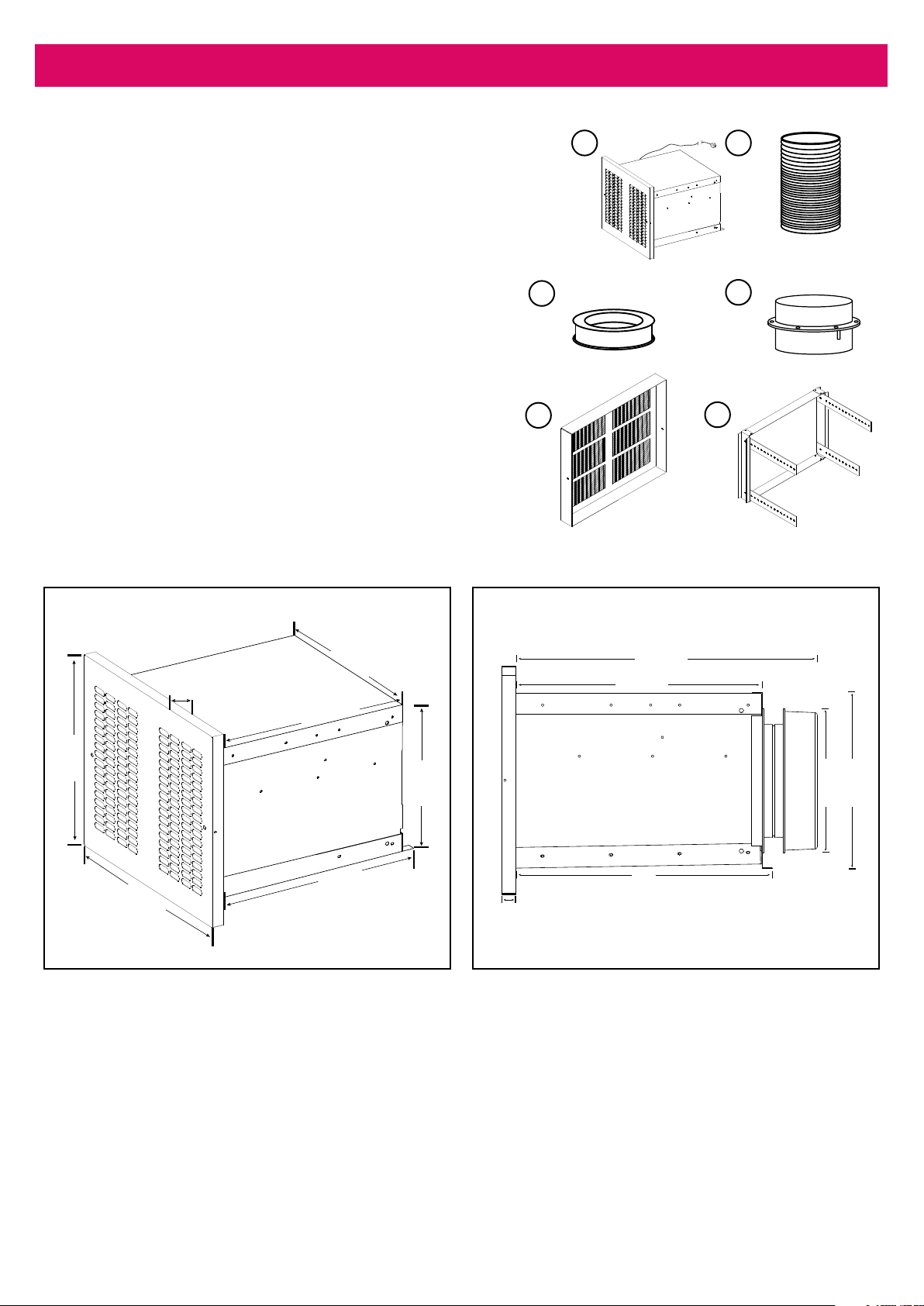
3. Description
Endline Isodrive System 1350
Included in the box:
1. Isodrive 1350 motor + housing
Approx. 5 metre, 10amp cable and standard male plug
2. Flexible ducting
1
Approx. 6 metres, 200mm (210mm OD
3. Bell-mouth adopter ring 200mm
4. Back Draught Shutter
Not included in the box:
Optional Accessories
5. Fire guard - Part number: P3024
6. Rear mounting bracket - Part number: EL RMB
build assy
Dimensions
) diameter
1
3
5
2
4
6
335mm
395mm
21mm
334mm
360mm
372mm
257 mm
Side viewAngle view
21mm
440mm
360mm
372mm
257 mm
198 mm
Page 7
Page 8

4. Installation
Installation Overview
Grille
Motor Housing
Inside wall
Outside wall
Male plug to rangehood plug
200mm exible ducting
Female plug
to motor
Male plug to
mains power
Rangehood
1
OD refers to outside dimension.
Wall Installation
1. Remove the Endline Isodrive 1350 Motor System
from the packaging.
2. Undo the 2 screws holding front grille and the
deector, and remove them from housing (See
gure 1A, pg.10).
3. Remove the foam packaging material that is
behind the grille.
4. Remove the motor from the housing and set
safely aside before proceding with the installation:
Lift the motor mounting bracket side anges up
and over the locating stops and remove the motor
assembly (See Figure 1B and Figure 2 on page 11).
5. Cut a wall aperture with measurements of 340mm
horizontally and 265mm vertically ensuring the
vertical cuts are at 90 degrees to the horizontal
cuts (See Fig.3, pg.12); if you have less than
40mm of depth in the wall aperture — or the wall
requires extra stability for the motor housing to
be installed — you may need to reinforce the wall
with noggins and use the optional rear mounting
bracket (See Optional Accessories,
page 7, and Figure 6, page 13).
6. To prevent water ingress apply a high quality
adhesive sealant to the rear of the front ange of
the motor housing, ensuring that the entire gap
between ange and wall is sealed (See Figure
1A, pg10; and Figure 4, pg.12) and secure motor
housing to wall using 4 attachment screws (see
gures 1A, 4, 5). Remove excess sealant that is
extruded from the joint.
Page 8
Page 9

5. Installation
Note: If you require extra support to stabilise the
motor housing, you may use the optional accessory:
rear clamping assembly (attachment screws not
necessary), (see Fig.6, pg. 13).
7. Once the motor housing has been screwed and
tted securely to the wall. Insert the motor
assembly, making sure the internal electrical plug
is connected into the mounted power outlet inside
the housing (see Fig.1A, pg. 10, Fig.1B, & Fig.2,
pg.11).
8. Install the Front Grille and Deector, and secure
using grille attachment screws (see Fig. 1A, pg.10).
NOTE: A Fire Ember Mesh Guard may be required
when installing the Endline Isodrive 1350 Motor
System in a BAL (Bushre Assessment Level area).
This is an optional accessory (see pg.7 and Fig.7,
pg.14).
DO NOT increase the length of exi duct beyond
the recommended installation lengths. See
Recommended Installation Distance on page 5.
Page 9
Page 10

5. Installation
Full Body Assembly Cross Section
Power supply
cord must be
at the top
2
Air inlet
Note:
Minimum
inlet area
17,000 mm
Duct attachment bellmouth
for 200mm ducting
Completely seal the joint between outer ange and wall to prevent water ingress
Housing
into building. Seal the full perimeter using premium quality bonding urethane.
attachment
screws
Vertical wall with suitable anchorage for housing
Removable fan and shutter assembly
Flange to locate
against stop
1 Degree
Base of housing has a one degree downwards slope from rear to front.
This will ensure drainage through the front grille drain holes
Side rails -- Motor assembly support
Vertical wall with suitable anchorage for housing
Stop
Anchor housing to wall structure by screwing through housing ange.
Ensure that ange perimeter is sealed against wall structure to prevent
water ingress into building
Figure 1A
Page 10
Deector
Grille
screws
Housing
attachment
outlet.
cover or
NB: Do not
restrict the
Grille
screws
attachment
Page 11

Removal of Motor Assembly
Removable Motor Assembly
Insert electrical plug fully
into mounted power outlet
inside housing
5. Installation
Figure 1B
Removal of Motor Assembly: Front or Rear
FRONT
Motor mounting
REAROR
TO REMOVE: Slide removable assembly
along side rails lifting the motor
mounting bracket side anges up and
over the locating stops.
bracket
SIDE RAILS — MOTOR ASSEMBLY SUPPORT
Fan and shutter assembly
INSTALLATION NOTE: Align shutter
assembly and bellmouth, position the ange
end so it locates behind the rail stop and is
resting on the rail.
Ensure shutter assembly engages
into bellmouth when installing
Figure 2
Stop
Page 11
Page 12

5. Installation
Wall Cut Out
265-270mm (vertical)
40 mm
(minimum)
340 - 345mm
Building wall shown
Wall Aperture Cut Out
(horizontal)
Figure 3
Motor Housing to Wall Fitment
NOTE: Attachment screws
and wall anchors not
provided.
NOTE: Front grille this side.
Completely seal front ange
to wall joint using high
quality bonding urethane all
four sides
Wall
Completely seal front ange to wall
joint using high quality bonding
urethane all four sides
NOTE: Ducting
this side.
Support body at vertical walls
if possible to ensure forward
slope draining
Figure 4
Page 12
Wall
Not to scale
Page 13

Front view of motor housing (Looking behind the front grille)
5. Installation
Figure 5
Housing attachment hole
Diagonal dimensions must be
within 2mm of each other
472mm 472mm
Housing attachment hole
Housing attachment hole
296mm
Housing attachment hole
368mm
Installation using optional rear clamp assembly
Clamp to body
tment 4 places
Fit screw from
inside body
Nuts
Load plate
Outer nut
Figure 6
Black dots cover
screw holes
Rear clamp assembly
(optional part)
Load plates
Page 13
Page 14

5. Installation (optional)
Attaching optional re ember Mesh Guard
Can be tted to any installation with access to the front.
Fire
Fire guard
frame
Normal
grille
guard
frame
Motor
housing
Guard is attached by screwing through
Mesh
45mm
deep
NOTE: Every 6 months check re guard wire mesh and clean if required.
Figure 7
20mm
deep
both sides of guard into existing grille.
Page 14
Page 15

6. Flexible Ducting Installation
Flexible Ducting
Flexible ducting must be fully extended and cut to the required length upon installation. Maximum fan
performance will not be achieved unless the ducting is fully extended. Failure to fully extend ducting results in
a smaller air passage and lower airows. Incorrect installation may reduce airow or increase noise levels. Call
outs relating to incorrect installation will result in a service fee directed to the customer. Schweigen will take no
responsibility for problems caused by faulty installation. A list of preferred Schweigen installers can be
obtained from the Schweigen website www.schweigen.com.au.
Shallow Space
In shallow roof spaces, do not crush or kink exible ducting, as it will reduce air ow severely. 90 degree curve
made of PVC or galvanise can be used as a substitute for the bend, refer to gure 12.
Use 90 degree curve
PVC or galvanise curve to
prevent crushing
Figure 12
Important Note
Please do not crush or kink exible ducting, as it will reduce air ow and may cause noise to occur through the
system. Ducting needs to be kept taut at all times. Refer to gure 13.
Figure 13
Page 15
Page 16

6. Flexible Ducting Installation
Securing Flexible Duct (Example)
Flexible duct must be installed with supports at maximum intervals of 1.0 metres. Flexible ductwork can be
supported by using good quality aluminium foil tape. Provided that it does not restrict the internal diameter of
the ducting. Ducting installed looped over hanging beams should be installed in such a manner as to ensure the
changes of direction are gradual. Support of the ducting with the use of hangers may be required, see option 2.
NOTE: Ducting should be kept taut at all times.
Aluminium foil
tape
Option 1
Secure the exible duct.
Option 2
Support exible duct
by using hangers.
NOTE: Care shall be
taken to minimize
sagging or snaking
of the duct between
supports.
Hanger
Aluminium foil tape
Page 16
Figure 14 Examples of securing ducting
Page 17

7. Parts List
Parts List for Isodrive Motor 1350
EL Base Build Assy
P3024 (Optional)
P3012
200mm Boss
Build Assy
P3036
P3013
P3011
(Optional)
EL RMB build assy
(Optional)
EL Inlet Build Assy
Part Number Description Quantity
P3036 Eliso1350 - Vinidex: 150mm x 50mm Pipe 1
P3024 Eliso1350 - Fire Guard Optional
P3013 Eliso1350 - Deector 1
P3012 Eliso1350 - Grille 1
P3011 Eliso1350 - Installation Plate Optional
El Rmb Build Assembly Endline 1350 Rear Mounting Bracket
El Inlet Build Assembly Endline 1350 Inlet Assembly (1 Bell Mouth Adaptor, cut to length
Optional
1
150mm Pipe and 1 Modied Bell Mouth Adaptor)
El Base Build Assembly Eliso1350 Modied Base with cut to length 150mm Motor Inlet Pipe 1
200Mm Bdss Build
200mm Back Draft Shutter System 1
Assembly
Page 17
Page 18

8. Maintenance / Specications / Warranty Information
Restoration or Cleaning
Before doing your wall restoration or cleaning, please completely cover the outside motor system and avoid all
chemical contact.
IMPORANT
Any damages caused by the
use of chemical products are
not covered by warranty.
Figure 15 Avoid chemical contact to motor system
Specications
Endline Isodrive motor 1350
230-240V 50Hz
88W
Class T
IPX4
Warranty
The Endline Isodrive Motor has a 10 Year Replacement
Product Warranty. The consumer is responsible for
any charges associated with removal of the faulty unit
and installation of the new unit. The customer is also
responsible for any freight charges incurred in this
change over process.
Disclaimer
Under our policy of continuous product development,
product specications may change without notice.
Prospective purchasers should therefore check
with the retailer to ensure this publication correctly
describes the products being oered for sale. All
information supplied is to be used for general
reference purposes only and is on the understanding
that Schweigen Pty Ltd will not be liable for any loss,
liability or damage of whatever kind arising as a result
of any reliance upon such information. All pictures
used in the guide are for illustrative purposes only.
See Warranty Card for more information.
Page 18
Page 19

Notes
Page 19
Page 20

SCH00015
Australia 8/3-4 Anzed Court, Mulgrave 3170 Victoria. Phone 1300 881 693
Email sales@schweigen.com.au Web www.schweigen.com.au
New Zealand 5 Tolich Place, Henderson, Auckland 0610. Phone 0800 200 510
Email info.parex@emerson.com Web www.parex.co.nz
 Loading...