

Schwank ThermoControl Plus 4, ThermoControl Plus 2, ThermoControl Plus 1 Installation Manual

ThermoControl Plus 4
Eight controller circuits 1-stage
Four controller circuit 2-stage
Operating and
Installation Manual
Schwank Group
P.O.Box 988 2 Schwank Way @ Hwy. 56N
Tel:1-877-446-3727 Fax: 1-866-361-0523
ts
a@schwankgroup.com
www.schwankgrou
RL:2
JUNE2010
p.com IM100630

X
Content:
1 INTRODUCTION ............................................................................................... 4
2 SAFETY ............................................................................................................. 5
3 Display and Button Function .............................................................................. 6
4 OPERATION ..................................................................................................... 7
4.1 Basic operation .......................................................................................... 7
4.1.1 Further display information ........................................................................ 7
4.1.2 Selection of a control zone ......................................................................... 8
4.1.3 Activation and deactivation of a control-zone ............................................. 8
4.1.4 Special information in the base display ...................................................... 8
4.2 Display and change of occupied / unoccupied temperature ....................... 9
4.3. Display and modify time and date ............................................................ 10
4.4 Circuit/Zone Times ................................................................................... 12
4.4.1 How to display and read a zone time program ......................................... 12
4.4.2 How to clear a switch point ...................................................................... 13
4.4.3 How to clear a time program .................................................................... 13
4.4.4 How to protect the time program .............................................................. 13
4.4.5 Program the switch points ........................................................................ 14
4.5 Holiday program ....................................................................................... 15
4.6 Manual operation
FI
............................................................................ 16
4.7 Button for service maintenance mode ...................................................... 16
5 SET UP THE OPERATING PARAMETERS .................................................... 17
5.1 Enter the number of control zones ........................................................... 17
5.2 Set up system operation parameters ....................................................... 18
5.3 Adaptive heat recovery time .................................................................... 19
5.4 COPY ....................................................................................................... 20
5.5 Securely save or reload all parameters .................................................... 20
6 INSTALLATION ............................................................................................... 21
6.1 Electrical Supply ...................................................................................... 21
6.2 Sensor Connections ................................................................................. 22
6.3 Heater Connection ................................................................................... 22
Zone Configuration Diagrams
6.4 Standard Tube Heaters (single fire rate) .................................................. 22
6.5 Two-stage Tube Heaters ......................................................................... 23
6.6 Luminous Heaters .................................................................................... 23
6.6.1 Luminous Heaters - Jumper P1 ............................................................... 24
6.6.2 Luminous Heaters - Jumper P2 ............................................................... 25
6.6.3 Luminous Heaters - Jumper P3 ............................................................... 26
6.6.4 Luminous Heaters - Jumper P4 ............................................................... 27
6.6.5 Luminous Heaters - Jumper P5 ............................................................... 28
- 2 -

6.7 Exhaust Fan Output - Two-stage Luminous Zones .................................. 29
6.8 Alarm Contact Input ................................................................................. 29
6.9 Remote-Control .................................................................................. 29
6.10 Signal input fault ...................................................................................... 29
6.11 Temperature display ºF / ºC selection ...................................................... 29
6.10 Communication connection (CM232, CM485) ......................................... 30
6.11 Common fault signals .............................................................................. 30
7 TECHNICAL PARAMETERS ........................................................................... 31
8 WIRING DIAGRAMS ....................................................................................... 33
8.1 Standard Tube Heaters: single- and two-stage zones ............................. 33
8.2 Two-stage Tube Heaters: two-stage zones ............................................. 34
Two-stage Tube Heaters: Internal Burner Wiring ..................................... 35
8.3 Luminous Heaters: single-stage zones .................................................... 36
8.4 Luminous Heaters: two-stage zones ........................................................ 37
8.5 Wiring Diagrams: Overrides, Humidity Control, Temp. Averaging ........... 38
8.6 Temperature Sensor Characteristics ....................................................... 39
- 3 -

1 Introduction
The Schwank ThermoControl Plus 4 is suitable for single or two-stage gas-infrared heating
systems.
Dependant upon its operation the controller has one or two controller circuits.
Please read this manual carefully before installing or using the control-unit. Failure to follow the
notes and warnings will affect your guarantees. They are also a prerequisite for a professional
installation and correct handling.
Please pay special attention to chapter 2 “Safety“.
The ThermoControl Plus 4 is designed to be used for industrial/commercial building infrared
heating systems only. Other or further uses are not suitable.
Schwank will not be held responsible for any damages whatsoever resulting from incorrect use.
The controller measures the radiant and ambient temperatures in the space and switches the
heater(s) on/off by relays.
The controller features different operating programs.
-P1…P5: single- or two-stage controller for luminous gas-infrared heaters and tube heaters
Override day temperature mode +h
Available as a special optional feature is a setback override bu tton that manually extends the
programmed heating period. This bu tton is installed parallel to th e sensor. By pushing the button
(~1 sec.), the nominal value of the programmed temperature in t he selected control circuit is
maintained for an additional programmable time period. (Default 1h)
Programmed temperature values and operating programs
The temperatures and operating programs of each single control circuit are independently
selectable.
- Day- , night- or anti-freezing temperature , selected by a week program
- Continuous day-(
- Holiday program: the controller is able to save eight holiday periods, which are programmed
according to the calendar.
FIX) night-( FIX) or anti freezing temperature ( FIX).
Other Tools/Features:
– Illuminated display
– Selectable ºF / ºC temperature display
– Button for service maintenance operation mode
– Real-time clock with calendar, including automatic summer / winter time correction
– Outdoor temperature sensor (SA)
– ‘Smart’ adaptive recovery: based on outdoor temperature, adjusts system ramp-up to ensure the
desired occupied temperature is achieved at the programmed time.
– Remote controlled day-mode operation
– ‘On’ cycle record at each output
– Error-relay: relay switches on in any case of error
- 4 -

2 Safety
This is a 24VAC Class 2 low voltage
(24Vac) temperature controller. Use
only Class 2 rated power supply. Do
not install on voltages higher than
30Vac.
Read all information in this manual
before installing or programming the
appliance. Electrical installation and
wiring must conform to local and
national building and electrical
codes. Check the electrical
equipment regularly. Defective wire
etc. must be replaced immediately.
Be sure that power routed to the
controller has been powered ‘off’
before beginning installation or
installation of communication
modules. Lock out the power supply.
The Schwank ThermoControl Plus 4
must be mounted where it is not
affected by vibration or shock.
The feed/supply line must be
protected by the installer with a fuse
of maximum 16 A.
Install the ThermoControl Plus 4
ensuring conformity to the wiring
diagram located in the switchboard.
Minimum Wiring Connection:
It is the installer’s responsibility
to ensure that wire gauge is
sufficient to provide 24Vac from
the transformer to the controller,
and from the controller 24Vac
outputs to the external relays
that power heaters and exhaust
fans. The distance between the
power source and equipment
must be considered.
24Vac power from 100VA
transformer to the controller
with minimum 16 AWG wire
24Vac from controller outputs
to equipment power relays
with minimum 16 AWG wire
Connect sensor to controller
with minimum 18 AWG wire
Install the IR temperature sensor
between the radiant area of two
heaters at a height of 6 ft (2 m)
above floor. In this location the
controller receives the optimal
value of the comfort temperature
(radiant temperature plus
ambient temperature).
NOTE: If heating zones are dimensionally
large in size or there are extreme
temperature gradiants within the
zone, temperature averaging can
be achieved using four IR sensors
wired in parallel-series for each
zone.
- 5 -

X
3 Display and Button Function
Front panel layout:
1. I/O Main switch on / off
2. LCD Display: All functional and operating information is shown in the base display mode
(upper picture). If no button is pushed for more than one minute, the control unit
switches back to the base display.
3.
Push the button or the button to display the day or night set value. Use the +/-
buttons to modify the values.
4. + /
-
With these buttons the display values can be increased or decreased.
5. DISP “Display-button“: To change the display. This button also offers the ability to switch back
to the main menu immediately.
6. SEL “SELECT”: This button allows selection of a certain parameter shown in the display. The
chosen/selected parameter can be modified using the
7. Clock-button: display and modify time and date.
8.
FI
Toggles between programmed and FIXED modes.
+/- buttons.
9. PR To check and modify the weekly time program in the displayed control circuit.
10. CLR “Clear-button“: To delete a switch-point or a complete time program.
11. Copy This button can be used to copy time- and temperature programs.
12. ERROR The system-error lamp flashes for any kind of error. An flashing sign will provide
information about the cause.
13. ZONE To switch between different control circuits.
14.
15. SERVICE “Maintenance”: If this appears, please call your service professional.
To turn on/off the single control circuit.
16. Button to program holiday operation mode.
17. Button for service maintenance operation mode: all control circuits heat full load.
- 6 -

4 Operation
4.1 Basic operation
When starting the ThermoControl wit h the I/O -button an automatic disp lay-test is activated. The
controller starts with the factor y default program. The display then switches to the base-program,
which shows all the important operation information.
Indication of the
chosen control circuit
Actual control mode, in
this case:
mode
Indication of which relay output and which
sensor inputs are used in the specific
control circuit.
day
The exhaust fan is
working (optional)
Present status of the heater zone:
Measured temperature
in the space/zone
(18.2°C)
full load
partial load (only 2-stage control)
heater is turned off
4.1.1 Further display information
The main/base display give s all important operating
data, further information can be received by pushing
the DISP button.
Value of the entered freeze protection temperature
The displayed value can be changed by the +/-
buttons. Range of setting:
+3 ... +20 °C /
37 ...68 ºF
Display of the outside te mperature (only if an
outdoor temperature sensor SA is connected).
‘On’ cycle counter:
circuit time of both stages.
The 2-stage control shows the
(1,2).
Push the SEL button to
switch between the
stages. The data cannot
be deleted, after 999999
hours the display
switches back to zero.
- 7 -
.

X
4.1.2 Selection of a control zone
The controller display and its usage is
based on the display of the control
circuit. The control zone can be
selected by pushing the ZONE
button. All settings of the control zone
can be managed.
4.1.3 Activation and deactivation of a control-zone
To stop heating in a certain zone: select the zone, and push the button. The symbol will
indicate the deactivation of the zone. In the deactivated zone only temperature measurement and
display continue to work. Activate the control zone again by pushing the button.
4.1.4 Special information in the base display
While using the holiday-mode the
appear.
To stop or modify the holiday program push the
button (chapter 4.5).
During adaptive heat recovery (optimised heat time) the
OPT symbol appears. The activati on time of a specific
zone is dependent on the hi story of preheating
performance compared to the entered heating time. This
function can be deactivated onl y in the setup-menu. An
outside sensor SA is required for this feature.
Option: By pushing the override button the occupied
temperature mode starts for a pre-programmed time (0:00-
24:00h; default 1h). The +h symbol will appear. The
override mode can be stopped by using the
- 8 -
symbol will
FI
button.

4.2 Display and change of occupied/unoccupied temperature
The desired temperature for each control circuit can be programmed separately
Push the DISP button to switch the current display
back to the main displa y (automatic after one
minute if no button pushed).
The current
occupied/unoccupied
temperatures can be
displayed by pushing
button.
The values can be modified
by pushing
All modifications are saved
immediately.
The temperatures can be
changed within the range:
+3…+35 °C / 37 ...95 ºF
or
+/-.
- 9 -

4.3. To display or modify the base time and date of the controller
Cycle through the base time and date of the controller with the button. Modify any time or date
using +/-.
This function affects the base controller clock (all control circuits have a separate time program).
Push the button to display/modify time of day (in the picture: 14:03). Push the button again
to display/change the year (2007). Push the button a third time and the month and day (in this
rd
case: 3
month = March, 21st day) is displayed. In the upper display, “3 Day” indicates the third
day in the week, or “Wednesday”. ( 1= Monday, etc.)
Push the
button once more to switch the display back to the full normal clock display.
Press the DISP button to return to the base display,.
Setting the time and date
NOTE: symbols or figures, shown framed are blinking!
Day of Week
To change the time
press the SEL button.
First the minutes start to
blink (03). Modified
using +/-.
After pushing the SEL
button again, the hours
will start to blink. (14)
The hour can also be
changed with the
+/-
buttons.
Month Day of
Month
The time of day setting
is completed using the
button.
The display returns to
the year.
- 10 -

Set the year
After the time of day has been modified, set the correct year, month and day as well. Otherwise the
automatic summer / winter time correction won’t work properly.
To change the year press the
SEL button. The last two
figures will start to blink (06).
Modify with the +/- buttons.
Next push the button and
month and day of the month
respectively will be shown on
the display. When the year
has been modified, the day of
the week may change
according to the calendar (in
this case 3).
Set the month and day
To change the setting press
SEL. First the month (3) will
start to blink - modify the setting
with +/-.
To change the day of the month
push the SEL button again.
Now, the date starts to blink
(21). Modify the date using +/-.
Once more the day of the week
changes according to the
calendar (first fr om 3 to 6, then
to 7).
When the time/date setting is
complete push DISP. The
display switches back to the
base display.
- 11 -

4.4 Circuit/Zone Times
Each control circuit has an independent time program, which can be set or modified.
The time program is a series of different circui t times. The controller changes automatically from
occupied (day) mode , to unoccupied (night) mode or freeze protection mode-
A circuit/zone point of time to switch modes can be described as:
- time of day (hour and minute)
- temperature mode , or , which will start at the set point of time
- day of the week, or a number of days, when the switch mode time should be active
(1 = Monday, 2 = Tuesday ……7=Sunday)
- number of switch modes points of time (max. 19 times in one program)
4.4.1 How to display and read a zone time program
From the base display, to see the time program in the selected zone push the PR button.
The display will then jump to the first programmed switch point. Press the PR button repeatedly to
display the stored switch points one by one. Over the symbol the number of the switch point is
displayed. The upper part of the display " 1 2 3 4 5 Day" indicates which days of the week ( 1=
Monday…) the switch function occurs. With a few presses of the PR button you can see the full
weekly heating program. Two examples are shown here:
When you first press the PR
button the display will briefly
show the number of free switch
point locations (here:17 free
points).
At switch time point 1 (7:00)
day mode heating is
started. Then at switch time
point 2 (17:30) night mode
heating begins. Since these
two switch time points are
valid on the first five days of
the week (1 2 3 4 5 Day)
and there are no other
programmed switch time
points for the last two days (6
7) the entire weekly program
is described with these two
switch time points.
- 12 -
In this next example the
program is extended with
two additional points: on
Saturday ( 6 Day) at the
point 3 (8:00) day
mode
heating starts. At point 4
(12:45) frost protection
mode begins. This mode
will be active until the next
programmed point 1 is
reached on Monday.

4.4.2 How to clear a switch point
The numeric of a switch point is not fixed. If a switch point is deleted the numbers of the remaining
points will be reassigned so that there is no chance of gaps in the time program.
To clear or erase a switch time
point: select the point, push and
hold the CLR button. The
symbol CLR will blink in the
display, warning that a switch
time point is to be cleared. If the
CLR button is released
immediately, then the erasure
procedure will be stopped.
If the erasure is completed
horizontal lines are visible. Then
the new number of free switch
points is displayed.
4.4.3 How to clear a whole time program
To clear a whole time program
push and hold the CLR button
while the number of free spaces
are shown in the display (FrEE).
The symbol CLR will start to
blink as a warning. If the CLR
button is released immediately,
then the erasure procedure will
be stopped.
If the erasure is completed
horizontal lines are visible. Then
the new number of free switch
points is displayed.(19).
4.4.4 How to protect the time program
The function of the time program is based on the clock and calendar data.
The clock is supplied by a batte ry (1.5 V AA). A warning signal shows, when the battery needs
replacement. For a 2 minute period while changing the battery, the exact time and date will remain
intact.
In case the control-unit is not used for a long ti me, including a complete discharge of the batteries,
the time and date will require confirmation of correctness or resetting after a battery change.
The saved switch points are independent of the battery. The pr ogram is saved on a secured
EEPROM-memory . Time programs cannot be lost as a consequence of a battery change or
discharge.
- 13 -

4.4.5 To program the switch points
In this example we program the following criteria: The day
temperature should start every morning at 7:35 from Monday
through Friday. First search for a free switch point ( - -:- -) by using
the PR button. Then press the SEL button and +/- to modify the
new data. The same procedure ca n be used to modify existing
switch points.
At first the temperature mode
starts to blink. The mode
or can be selected using
+/- buttons.
the
Then press the SEL
button to select the day
program. The entire
week appears: 1234567
Pressing
different day groups or
only single days
(1=Monday).
Next press the SEL button to
modify the hour of the day
(12). The required time (7) can
be set with +/-.
Then press SEL to select the
minutes (00). The required
time (35) can be set with +/-.
Finally press the PR button to
set the switch time program.
The display then changes to
the next free switch point.
+/- selects
It is not possible to program two different switching points with the same time parameter. In the
case of a mistake saving two switching points for the same time, t he time of the last
programmed point will be corrected by one minute.
In this case a new switch point
was programmed with a time of
7:35. This time parameter was
used previously in switching
point 3. Thus the time for point 4
changes automatically to 7:36.
- 14 -

4.5 Holiday program
The controller provides the opport unity to program 8 holidays. Start and end of the holiday is
displayed with exact data (year, month, day). The programs can be c hanged and also stopped at
every point of time.
During the holiday program the freeze protection temperature will be maintained.
To program holiday periods push the
First the number of the holiday program HOL 1 (holiday 1) appears. The numeric above the
holiday number shows which of the 8 holiday programs is activated. A programmed holiday period
starts automatically at the programmed date. Within the SEL button you are able to start or stop
the programmed holiday period. If the program is switched off (program number does not appear)
it won’t start, a running program would be shut down respectively. Use +/- to select one of the 8
holiday programs.
The holiday program activates in all control circuits that are set to the automatic mode . If a
control circuit is working on a fixed mode (FIX), the holiday program does not come into effect.
button.
Push the button again to modify the start of the
holiday period (A): by pressing +/- you can set up year,
month and day.
The holiday program starts off at 0.00 o’clock on the
desired date.
After modifying the start (A), you will have to set up the
end (B) of the holiday period. To set the date use the
+/- button. The holiday program ends at 0.00 o’clock on
programmed day.
The ERR symbol can appear while you are programming
a holiday:
- if start date A is later than the programmed end of the
holiday period B
- if the end of the period B is earlier than the present
date.
A program that indicates one of these problems won’t
start.
If all errors are eliminated the ERR –symbol disappears.
Press
switches back to HOL.1. Now you can select the next
holiday program and start its modification, otherwise
you can get back to the main display by pushing the
DISP button.
button to finish programming, the display
- 15 -

X
X
X
X
4.6 Manual operation
Use the
FI
button to select different operating modes.
FI
Press DISP when the desired operation mode
appears (for example: continuous FIX mode). The
control-unit switches back to the main display and the
selected mode is activated.
day-temperature mode
night-temperature mode
freeze protection temperature
Push
FI
to return to the main display.
4.7 Button for service maintenance mode
To change the FIX
mode push the
FI
button.
For service or maintenance, to have the heater(s) in full
operation regardless of the current room temperature, push
the
button. Switch back to the base display mode by
pushing this button again.
- 16 -
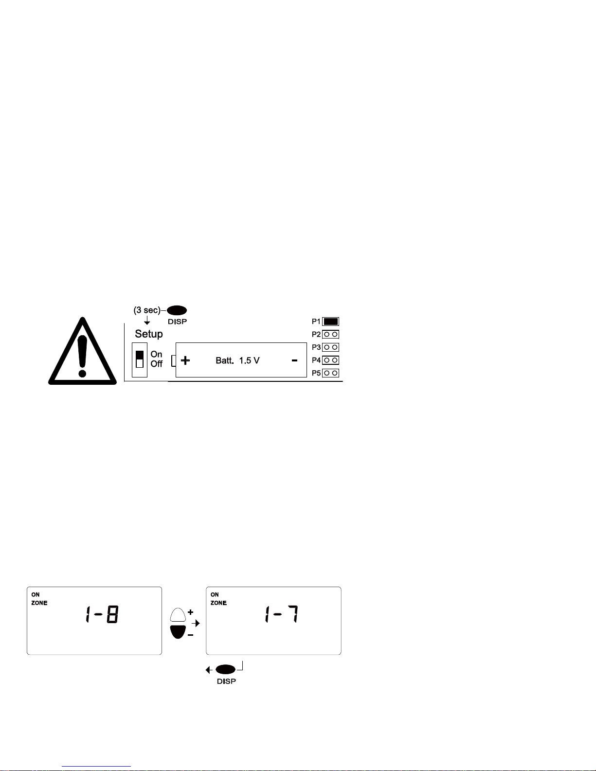
5 Set up the operating parameters
The “setup” switch as well as the jumper selection of the program P1 … P5 may only be
changed after the main power to the controller has been switched off. Before you open the
control unit read the important information in chapter 2! The set up of operation parameters
can be modified from the front panel with the “setup” switch in the “On” position. Only a trained
and knowledgeable technician should modify the operating parameters. After setting up the
operation parameters, turn off main power and switch the “setup” switch to the “Off” position to lock
the parameters.
To access the setup switch: The switch permit setup: “ON”, locks the setup: “OFF”.
Switch off the main electrical supply before changing the switch position between
“On” and “Off”. It is not sufficient to switch off the I/O switch on the front panel of the
controller, the external main switch must be switched off to avoid electric shock or possible
damage to the module.
Open the case cover door and loosen the four big plastic screws at the corners to release
the outer enclosure case.
Setup switch is located inside the outer enclosure case to the left side of the battery.
- All zones single-stage
- 1 zone 2-stage, up to 6 single-stage
- 2 zones 2-stage, up to 4 single-stage
- 3 zones 2-stage, up to 2 single-stage
- 4 zones 2-stage
The application program is selected at the controller unit (P1, P2, P3, P4, P5). Perform this
operation with the main power supply switched of. Place the “jumper“ in the correct position. Only
one program can be selected at any one time. Double check that the jumper is positioned for the
correct application program!
If the application program is changed (jumper moved) after set up, all parameters switch back to
the default factory setting (chapter 5.1 and 5.2)!
P1 - Eight control circuits, single-stage
P2…P5 - Variations of control circuits - combines single- and two-stage zones
5.1 Enter the number of control zones
The controller is able to manage one or two control zones, depending on the chosen application. In
the following example the actual number of control zones are set.
Push the DISP button to return to the normal functions.
Hold the ZONE button for about 3
sec.. The number of available
control circuits appears in the
display (for example.: 1-8: four
control circuits). The desired
number of control circuits can be
selected by pushing +/- (1-7).
- 17 -

5.2 Set up system operation parameters (suggested settings are circled)
To set up the parameters hold the DISP button
for approximately 3 seconds. The “PAr” symbol
appears briefly. The operation parameters can
SEL button.
1.8
°F
be selected with the
Proportional Gain: Two-stage mode
only: 0.5...3.0 °C / 1.0...5.5 ºF
Suggested Setting: 1.0°C / 1.8°F
In single-stage mode: (--.--) appears
Integration time: Two-stage mode
only: 10 … 99 minutes
Suggested Setting: 30 minutes
In single-stage mode, or in off-state
(--.--) appears.
°F
1.2
Ability of a restart:
Single stage heaters
in 2-stage system
2-stage heaters
Hysteresis
0.2 … 2.0
Suggested Setting: 0.7°C / 1.2°F
, can be activated by
°C / 0.4...3.6 ºF
Sensor correction: if the sensor could
not be mounted at the optimal location,
the measured temperature can be
revised: -9.9..+10.0 °C / -9.9..+10.0 ºF
t1: Heater starts and runs at full power
then stops at the programmed time, in
this case: 0…5 minute.
t2: For the displayed time, the heater
stops completely (5..60 Sec). it only
appears, if t1 doesn’t equal zero.
t3: Set to “0” for single stage heaters,
set to “1” for 2-stage heaters. Heater
starts at full load for 1 minute, then the
controller switches to the regular mode
(0: off). It does not appear unless the
two-stage control is selected.
Minimum heater run time: ( 0...15
min)
Suggested Setting: 5 minutes
Override Duration: +h (0:00-
24:00)
Suggested Setting: 1:00 hour
- 18 -

Refer to sections 6.4 to 6.7 for
exhaust fan output use
Switch off exhaust fans:
’AUto’: exhaust fan in use = for two-
stage luminous zones ONLY,
’OFF’’: exhaust fan output is switched
off for all tube heater zones, and
single stage luminous zones
(the symbol disappears).
Exhaust fan post-purge time
:
After a heating zone (two-stage
luminous) has been switched off, the
exhaust fan can continue to run until
the set time is achieved: 0 to 60
minutes (available only in the ”AUto”
ventilation mode).
Adaptive (Optimized) heat recovery
time can be switched on (AUto) or
off(OFF). The effective warm up time
is shown.
Display illumination duration:
1…..9 minutes; enable (ON) or
disable (OFF) display illumination.
If a communication module is integrated into the controller, other parameters will follow.
Auto switch summer to winter time
(+/- 1h).
This function can be activated (AUto)
or deactivated (OFF).
Feature selection of the contact
input no. 72-73:
: remote contact
RES-ERR: signal input - Error
5.3 Adaptive heat recovery time
The adaptive heat recovery time is active only if the sensor Outdoor Ambient Temperature Sensor
OAS is connected to the controller, and the function is programmed to “Auto” in any heating zone.
Each control circuit has a separate and individual adaptive heat recovery time. When set to “Auto”
the program works automatically and doesn’t need to be programmed or adjusted. The controller
‘learns’ and switches on the system to achieve occupied temperature at a different time than
originally programmed, so that the desired temperature is achieved at the required time. The
heating characteristics of the heating zone and temperature difference from inside to the current
outside temperature are integrated in the calculation for the recovery time. The control unit adjusts
the start point of the recovery time to the current situation.
- 19 -

5.4 COPY
The COPY button offers the opportunity to copy all parameters of a certain circuit or the complete
time program and insert it into the program of one or many other control circuits.
To copy parameters hold DISP (approx. 3 sec.,
chapter 5.2).
To copy time programs use the PR button (chapter.
4.4.1).
This example copies data from Zone 1 to Zone 2.
Push either the DISP (parameters) or PR (time
program) button
Zone 2 symbol start to blink. “COPY“ appears in the display
to indicate the copy mode. Push COPY to paste the Zone 1
data to Zone 2 (heating area 2).
5.5 To securely save or reload all parameters:
The setup technician can save all operational parameters to memory. If the parameters are
changed unintentionally, the old parameters can easily be re-established using the data saved in
memory. It is also possible to reload the factory default settings.
To Save: Press CLR and +
simultaneously. The “SAVE”
symbol appears in the display.
Push DISP, the display will blink
while the parameters are saved.
Once saved the display
switches back to the main
menu.
The data of Zone 1 is now also located in Zone 2. The
Zone 2 symbol stops blinking to indicate the completion of
the copy process.
The data can continue to be copied to other Zones by
selecting Zone 3 to Zone 8 using the SEL button.
To finish copying the parameters press DISP button, or
press the PR button to finish copying time programs.
To Load: Press CLR and SEL simultaneously, the
“LOAd” symbol appears in the display. Press the DISP
button and the parameters that were saved by the setup
technician, will reload. Switch from “LOAd” to
“FACt“, using the +/- button. If “FACt” appears in the
display push the DISP button to re-establish the factory
default parameters.
- 20 -

6 Installation & Configuration
Door
6.1 Electrical Supply
Lock
Bracket
Lower part
Upper part
Screw
140
25
96
265
244
180
205
The controller must be electr ically grounded in accordance with the National Electrical
Code. ANSI / NFPA 70 or current Canadian Electrical code CSA C22.1.
Appliance and control wiring must be in accordance with all applicable local codes.
The controller must be isolated from the main power supply during installation or
connection work is carried out! The "Off" position (O) of the controller I/O switch
does not provide complete isolation of the controller!
The controller power supply connection terminals are identified as "L 24V" and "COM". The "COM"
connection point is the common ground in the circuit: it is directly connected to the points of the
relay outputs marked "C", and it is the common point of the signal input terminals and the
communication terminal. The "L
24V" power supply is connected th rough a Fuse (6.3A) to the
connection terminal "L1". It is important to make connections correctly in accordance with the
wiring schemes of the selected application program!
Pay special attention to common ground when
connecting outside devices so that a short-circuit does
not occur.
If several ThermoControl units are connected to one
24VAC power supply, ensure to connect the same
terminals of the power supply to the "L 24V" and "COM"
terminals of the controllers.
- 21 -

6.2 Sensor connections
The sensor is connected with two wires. The sensor does not require shielded cable, because the
controller includes effective protection. The l ength of wire up to 650 ft (200 m) does not influence
the accuracy of the temperature measurement. Do not run the s ensor lead next to high voltage
wires. The sensor connection must match the selected operating program (single- and/or two-stage
zones). Unused inputs must be kept free of usage!
6.3 Heater Connection
Only 24Vac Class 2 equipment can be connected to the controller! The controller interior
relays switch 24Vac to the connection terminals (w et contact). Use 24Vac Class 2 rated power
relays to control heaters and ancillaries. Note that the total load is limited to 6.3 A.
6.4 Zone Configuration – Standard Tube Heaters (single firing rate)
Standard tube heater zones can be set up as single-stage, or two-stage. Two-stage zones have a
proportion of the heaters on low-stage, with the balance of the heaters in the zone on high-stage.
Refer to sections 5 and 5.2. A zone can contain up to ten standard tube heaters. The location of
the jumper in P1 … P5 determines the quantity of single-stage and two-stage zones. Refer to
configuration diagram below and wiring diagram (8.1) for standard tube heaters.
DO NOT USE FAN
(SEE SECTION 5.2)
FAN OUTPUTS
FOR TWO-STAGE
LUMINOUS ONLY
Eight relays supplied
OUTPUTS
Error Output
Jumper Pins are
located inside the
controller to the
right side of the
battery.
Jumper position
(P1 … P5)
determines the
zone strategy for
quantity of single-
- 22 -

6.5 Zone Configuration – Two Stage Tube Heaters
For two-stage tube heaters: All heater zones are set up as two-stage only. Pairs of controller
outputs control low and high fire. The location of the jumper in P5 establishes four two-stage
zones. A 100VA 120V/24V transformer is supplied to power the controller, and eight 24Vac
external relays are also supplied. Additional field supplied items required for EACH two-stage zone:
Qty 1 x 100 VA 120V/24V transformer; Qty 2 x external zone relays (one Low-stage + one Highstage); Qty 2 per heater in zone x external heater relays (one Low-stage + one High-stage). Refer
to configuration diagram below and wiring diagram for two-stage tube heaters.
DO NOT USE FAN
(SEE SECTION 5.2)
FAN OUTPUTS
FOR TWO-STAGE
LUMINOUS ONLY
OUTPUTS
Error Output
Jumper Pins are
located inside the
controller to the
right side of the
battery.
Jumper position P5
establishes all two-
6.6 Zone Configuration – Luminous (high intensity) Heaters
A luminous heater has a 24Vac ignition control module and gas valve. While individual heaters are
single-stage, heater zones can be set up as single-stage, or two-stage. Two-stage zones have a
proportion of the heaters on low-stage, with the balance of the heaters in the zone on high-stage.
The quantity of luminous heaters in a zone is typically limited by: the dimensional size of the zone;
capacity of exhaust fan to satisfy the total input of the zone.
The location of the jumper in P1 … P5 determines the quantity of single-stage and two-stage
zones. For single stage zones, zone relays (eight supplied) switch line voltage to field supplied
exhaust fan and transformer in each zone. Heating zone required exhaust volume is:
USA: 4 cfm/1,000 Btuh input; Canada: 300 cfm/100,000 Btuh input. Zone transformer sizing: 40VA
first heater + 20VA each additional heater in zone.
The configuration diagrams below indicate the single- and two stage zone strategies for Jumper
positions P1 to P5. Also refer to the wiring diagram for luminous heaters.
- 23 -

6.6.1 Zone Configuration – Luminous (high intensity) Heaters
JUMPER IN POSITION 1 (P1): Up to eight single stage zones (all single-stage)
The jumper pins P1 to P5 are located inside the controller cover to the right side of the battery. The
location of the jumper in P1 … P5 determines the quantity of single-stage and two-stage zones.
With the jumper in position P1, all zones are single stage. Eight relay switches are supplied with
the controller to switch line voltage to the zone exhaust fans (field supplied) and to the zone
transformers (field supplied). Single-stage zones are controlled by the heater outputs 20-35.
Single-stage zone exhaust fans are wired in parallel to the heater zone transformer.
The 120V/24Vac zone transformer is ‘sized’ to provide sufficient power to all heaters in the zone:
40VA for first heater + 20 VA for each additional heater.
Refer to the diagram below, and the wiring diagram “Luminous Heaters – Single-Stage Zones”.
Only use fan outputs
for two-stage zone(s)*
DO NOT USE FAN
(SEE SECTION 5.2)
FAN OUTPUTS
FOR TWO-STAGE
LUMINOUS ONLY
Eight relays supplied
Zone exhaust fans
OUTPUTS
Error Output
(field supplied)
Jumper Pins are located
inside the controller to the
right side of the battery
- 24 -

A
6.6.2 Zone Configuration – Luminous (high intensity) Heaters
JUMPER IN POSITION 2 (P2): One two-stage zones + up to six single-stage zones
The jumper pins P1 to P5 are located inside the controller cover to the right side of the battery. The
location of the jumper in P1 … P5 determines the quantity of single-stage and two-stage zones.
With the jumper in position P2, one zone is two-stage, and the balance of the zones are single
stage. Eight relay switches are supplied with the controller to switch line voltage to the zone
exhaust fans (field supplied) and to the zone transformers (field supplied). One additional field
supplied relay switch (P/N: JS-0568-CC) is required to power the exhaust fan for the two-stage
zone.
The fan for the two-stage zone is controlled by the controller fan outputs 10-11. Fans for the singlestage zones are controlled by the heater outputs 24-35. Single-stage zone exhaust fans are wired
in parallel to the heater zone transformer.
The 120V/24Vac zone transformer is ‘sized’ to provide sufficient power to all heaters in the zone:
40VA for first heater + 20 VA for each additional heater. A separate transformer is required for
each of the Low- and High-stage zones in two-stage Zone 1.
Refer to the diagram below, and the wiring diagram “Luminous Heaters – Two-Stage Zone”.
Only use fan outputs
for two-stage zone(s)*
STAGE ZONE
dditional relay for fan
(field supplied)
Zone exhaust fans
(field supplied)
USE FAN
OUTPUTS
FOR TWO-
ONLY
Eight relays
supplied
Error Output
Jumper Pins are located
inside the controller to the
right side of the battery
- 25 -

A
6.6.3 Zone Configuration – Luminous (high intensity) Heaters
JUMPER IN POSITION 3 (P3): Two two-stage zones + up to four single-stage zones
The jumper pins P1 to P5 are located inside the controller cover to the right side of the battery. The
location of the jumper in P1 … P5 determines the quantity of single-stage and two-stage zones.
With the jumper in position P3, two zones are two-stage, and the balance of the zones are single
stage. Eight relay switches are supplied with the controller to switch line voltage to the zone
exhaust fans (field supplied) and to the zone transformers (field supplied). Two additional field
supplied relay switches (P/N: JS-0568-CC) are required to power the exhaust fans for the twostage zones.
The fans for the two-stage zones are controlled by the controller fan outputs 10-11 and 12-13.
Fans for the single-stage zones are controlled by the heater outputs 28-35. Single-stage zone
exhaust fans are wired in parallel to the heater zone transformer.
The 120V/24Vac zone transformer is ‘sized’ to provide sufficient power to all heaters in the zone:
40VA for first heater + 20 VA for each additional heater. A separate transformer is required for
each of the Low- and High-stage zones in two-stage Zones 1 and 2.
Refer to the diagram below, and the wiring diagram “Luminous Heaters – Two-Stage Zone”.
Only use fan outputs
for two-stage zone(s)*
dditional relays for fans
(field supplied)
Zone exhaust fans
(field supplied)
USE FAN
OUTPUTS
FOR TWO-
STAGE
ZONES
ONLY
Eight relays
supplied
Error Output
Jumper Pins are located
inside the controller to the
right side of the battery
- 26 -

A
6.6.4 Zone Configuration – Luminous (high intensity) Heaters
JUMPER IN POSITION 4 (P4): Three two-stage zones + two single-stage zones
The jumper pins P1 to P5 are located inside the controller cover to the right side of the battery. The
location of the jumper in P1 … P5 determines the quantity of single-stage and two-stage zones.
With the jumper in position P4, three zones are two-stage, and two zones remain for single stage.
Eight relay switches are supplied with the controller to switch line voltage to the zone exhaust fans
(field supplied) and to the zone transformers (field supplied). Three additional field supplied relay
switches (P/N: JS-0568-CC) are required to power the exhaust fans for the two-stage zones.
The fans for the two-stage zones are controlled by the controller fan outputs 10-11, 12-13 and
14-15. Fans for the single-stage zones are controlled by the heater outputs 32-35. Single-stage
zone exhaust fans are wired in parallel to the heater zone transformer.
The 120V/24Vac zone transformer is ‘sized’ to provide sufficient power to all heaters in the zone:
40VA for first heater + 20 VA for each additional heater. A separate transformer is required for
each of the Low- and High-stage zones in two-stage Zones 1 and 2.
Refer to the diagram below, and the wiring diagram “Luminous Heaters – Two-Stage Zone”.
Only use fan outputs
for two-stage zone(s)*
dditional relays for fans
(field supplied)
Zone exhaust fans
(field supplied)
Error Output
Eight relays
supplied
Jumper Pins are located
inside the controller to the
right side of the battery
- 27 -

A
6.6.4 Zone Configuration – Luminous (high intensity) Heaters
JUMPER IN POSITION 5 (P5): Four two-stage zones
The jumper pins P1 to P5 are located inside the controller cover to the right side of the battery. The
location of the jumper in P1 … P5 determines the quantity of single-stage and two-stage zones.
With the jumper in position P5, all four zones are two-stage. Eight relay switches are supplied with
the controller to switch line voltage to the zone transformers (field supplied). Four additional field
supplied relay switches (P/N: JS-0568-CC) are required to power the exhaust fans for the twostage zones.
The fans for the two-stage zones are controlled by the controller fan outputs 10-11, 12-13, 14-15
and 16-17.
The 120V/24Vac zone transformer is ‘sized’ to provide sufficient power to all heaters in the zone:
40VA for first heater + 20 VA for each additional heater. A separate transformer is required for
each of the Low- and High-stage zones in each of the 4two-stage zones.
Refer to the diagram below, and the wiring diagram “Luminous Heaters – Two-Stage Zone”.
Only use fan outputs
for two-stage zone(s)*
dditional relays for fans
(field supplied)
Jumper Pins are located
inside the controller to the
right side of the battery
Zone exhaust fans
(field supplied)
Error Output
Eight relays
supplied
- 28 -

X
6.7 Exhaust fan output connection – For Two-stage Luminous Zone ONLY
REFER TO ZONE AND EXHAUST FAN SCHEMES IN 6.6 AND LUMINOUS HEATER WIRING
DIAGRAM. Exhaust fan output connections (10 to 17) are reserved for luminous two-stage
zones ONLY! Use 24VAC Class 2 rated power relay (field supplied) to switch line voltage to an
exhaust fan that serves both the proportion of heater in the low-stage zone, and the balance of the
heaters in the high-stage zone.
Two control circuit outputs belong to one common exhaust fan control output. For example:
connections 10-11 is the common exhaust fan for heating outputs 20-23 = zone 1-Low and zone 1High. If one or both heating zone outputs are activated, the exhaust fan output will be activated
also. When both heating zone outputs switch off, the exhaust fan also switches off immediately or
can be delayed (run on) to switch off after a programmable period of time (chapter 5.2).
For single stage zones the exhaust fan is controlled by the heater outputs 20-35 and the exhaust
fan outputs should be locked off (chapter 5.2).
6.8 Alarm contact input (e.g.: Fire Alarm system input, etc.)
Connect dry contact to this input. The contact must be provided by low voltage Class 2 rated
equipment. If the dry contact is interrupted, the controller switches off all heaters and exhaust fans
independently. At the same time “ERROR” starts to blink on the display and the “ALr” symbol
appears in the display. If the contact is not used, bypass the connections.
6.9 Remote-Control
Connect dry contact to this input. The contact must be provided by low voltage Class 2 rated
equipment.
The feature Remote-Control can be selected in the SETUP-Menu (5-2). The controller switches to
day mode in both zones, if the remote contact is activated. The display shows the symbol. If
the remote contact is not used, bypass the connections.
If the remote contact is activated it
is not possible to change the
operating mode by using the
FI
button. A warning signal "rE.c"
(remote contact) appears in the
display.
6.10 Signal input fault
Connect dry contact to this input. The fault signal must be provided by low voltage Class 2
rated equipment.
The feature contact input fault can be selected in the SETUP-menu (5-2). The external error
message can be connected to inputs 72-73. In case of an error message (option) the signal ERR
and RES as well as ERROR light begins to blink. At the same time the Error relay switches on. The
operation mode of the controller is not changed due to the error signal.
6.11 Temperature display ºF / ºC selection
Switch off main power supply before making any changes to this jumper! Select the ºF / ºC
temperature display mode by jumper location (see figure 6.4 Wiring Connection ). After selecting
the readout all displays and settings will automatic ally appear with the se lected mode. Factory
setting of this selection is ºF. Set values for ºF / ºC are stored separately - after modifying selection
you must set actual values (no automatic conversation here).
- 29 -

6.12 Communication connection
Two types of optional communication cards can be used and connected to the "Communication"
terminal (only one type can be used at a time):
-CM485 card: Modbus (RS485) output, standard interface to building and industrial supervisory
systems. The output of this card is optically isolated from the controller.
-CM232 card: RS232 output, built-in 3-weeks data logger. Direct connection to telephone modem
or PC. Stored data can be downloaded to PC, remote setting of the controller from the PC.
The signal output ground of the CM232 module is directly connected to the controller's
common ground "COM". If the signal line of the connected computer is grounded, the
common ground "COM" of the controller will be grounded as well. This will change state
from isolated to grounded.
6.13 Common fault signal
In case of any operational error the red “ERROR” symbol starts to blink, simultaneously the error
relay switches on (connections 1, 2, 3). The display shows the affected control zone. Type and
cause of the problem is also indicated by other symbols displayed. To select another control zone
press “ZONE” - in doing so, the red “ERROR” signal won’t disappear, because the cause of the
problem is not yet solved. The blinking “ERROR“ signal and the activated error relay can be
deactivated by switching off the operational function of the zone using the button.
Sensor error: The temperature sens or is not properly
connected. It is damaged or short-ci rcuited. Verify connections
and wires. In case of any sensor error the controller does not
switch off the heater zone (relay output is kept activated).
Battery error: Battery low or discharged. Replace the battery
immediately. The battery is located inside the control unit cover.
Type: 1.5V (AA). Use long-life batteries. Before changing the
batteries please read the general se curity instructions – and in
particular Section 4.4.4!
This is an error message (opti on) of a heater (connections 72-
73). The operation mode of the controller is not changed due to
the error signal.
Alarm signal: Does not point out the kind of operational error.
It only shows that an error message has arrived at the “alarm
contact”. The controller swit ches off all heaters and exhaust
fans. If the “alarm contact” is not used the connections should
be bypassed.
This display is a very rare erro r: a forced position of a button at
the front panel. Please check!
- 30 -

Holiday Programming: When modifying the holiday program
the “ERROR“ signal will appear if the starting(A) or ending(B)
dates or calendar data are in conflict. (for example: the end
date is earlier than the start date of a holiday period) In case of
data entry error, the holiday program won’t activate.
This display represents a very rare error: a button on the front
panel is jammed in the depressed position.
Please check button orientations!
- 31 -

7 Technical
Relay outputs: 8 control relays - up to 8 heating zones, (4 flue fan relays – Reserved – Do Not
Use).
Relays switch out 24Vac to connection terminals (wet contact).
1 error relay: connected as voltage-free contact to connection terminals
Relay load: max. 6.3A 24V 50/60Hz (inductive)
Inputs: Temperature sensors: 2-wire connection
SR - black-bulb IR/Ambient temperature sensor (NTC)
OAS - outside ambient temperature sensor (NTC)
Contact inputs: potential free contacts, closed if not used
Connected appliances must meet low voltage Class 2 requirements
Alarm contacts
Remote : Forced day mode operation or Signal input fault contacts
(selectable)
Set values: The values of each zone can be modified separately:
Type: Day mode:
Night mode: +3...+35 °C / 37...95 ºF
Freeze Protection mode: +3...+20 °C / 37...68 ºF
Holiday program: 8 programmable holiday periods (calendar dates)
Application: Luminous and tube type gas-fired radiant heaters; programmable
Hysteresis : 0.2 … 2.0 °C / 0.4 ... 3.6 ºF
Integration band: (two-stage operation only): 0.5 …3.0 °C / 1.0...5.5 ºF
Integration time: (two-stage-heater operation only): 10 ... 99 minutes
Sensor correction: -9.9…+10.0 °C / -9.9...+10.0 ºF
Exhaust fan delay (run on) time: 0 …. 60 minutes
Clock, calendar: Real-time clock with calendar
Clock power: 1.5 V AA battery, durability: ~ 3 years
automatic summer / winter time correction (+/- 1 hour):
can be deactivated
correction to summer time: second Sunday in March
correction to winter time: first Sunday in November
Time programs: Independent weekly program in each zone:
19 switching points
Saved on internal EEPROM-memory
Power supply: 24V+-20% 50/60Hz (terminals L 24V, Com) P
Must use Class 2 rated power supply
Fuse: F1 5x20mm 6.3 A (F) standard
Connections: Screw terminals, wire section max.: 11 AWG
Safety standards: UL 60950
Operating temperature: 0...50 °C / 32...122 ºF
Storage temperature: -10...60 °C / 14...140 ºF
Protection: NEMA13 / IP65
Housing: Plastic housing with transparent door (key lock); waterproof;
UV-resistant
Dimensions: 10-3/4’’ x 8-5/8’’ x 5-3/8’’ (275 x 220 x 140 mm)
+3...+35 °C / 37...95 ºF
(controller): 10 VA
max
- 32 -

8 WIRING DIAGRAMS - ThermoControl Plus 1, 2, 4
8.1 Standard Tube Heaters:
Single-stage zone; 1-8 Zones
Two-stage zones; 1-4 Zones (refer to section 5 and 5.2)
Wire each of the low- and high-stage zones as below
Jumper position and controller programming determine two-stage operation
- 33 -

8.2 Two-Stage Tube Heaters: 1-4 two-stage zones
(refer to section 5 and 5.2)
See internal burner wiring diagram next page
- 34 -

8.2.1 Two-Stage Tube Heater Internal Burner Wiring
See zone wiring diagram previous page
- 35 -

8.3 Luminous Heaters: single-stage; 1-8 Zones
- 36 -

8.4 Luminous Heaters: Two-stage Zones; 1-4 Zones
- 37 -

8.5 Wiring diagram, accessories
Option 1: Override Button
IR / Ambient
Temperature Sensor
NOTE: For humidity control (steel storage facilities, etc.) a humidity sensor can be connected in
parallel to the SR to operate the heaters if humidity rises above humidity set-point even
though temperature set-point may be satisfied.
Override Button
(or other override input)
Other inputs such as coin-operated equipment can also be connected in parallel to the SR.
Option 2: Average temperature determination,
Four SR sensors
- 38 -

8.6 Temperature Sensor-Characteristics
°F
32 14324
34 13539
36 12802
38 12110
40 11460
42 10848
44 10273
46 9732
48 9223
50 8744
52 8293
54 7867
56 7466
58 7088
60 6732
62 6395
64 6078
66 5778
68 5495
70 5227
72 4974
74 4735
76 4509
78 4295
80 4092
82 3900
84 3718
86 3546
OHM
16000
14000
12000
10000
OHM
Temperature Sensor-Characteristic
8000
6000
4000
2000
0
30 40 50 60 70 80 90
°F
Temperature Sensor-Characteristic
16000
14000
12000
10000
8000
OHM
6000
4000
2000
0
0 5 10 15 20 25 30
°C
°C
0 14324
1 13615
2 12946
3 12313
4 11715
5 11149
6 10614
7 10107
8 9628
9 9174
10 8744
11 8336
12 7950
13 7584
14 7237
15 6907
16 6595
17 6298
18 6016
19 5749
20 5495
21 5253
22 5024
23 4805
24 4598
25 4400
26 4212
27 4033
28 3863
29 3701
30 3546
OHM
- 39 -
 Loading...