

Page 1

SC80 Installation & User guide
Page 2

Index
Page 3: Product information and specs
Page 4: Trouble shooting
Page 5: Filter replacement
Page 6: CO2 bottle replacement
Page 7: CO2 adjustment
Page 8: Water temp adjustment
Page 9: Component checklist
Page 10: Install layout
Page 11: Ventilation requirements
Page 13: Instillation guide
Page 23: Unit setup
Page 29: Warranty
Page 30: Unit shut down
Page 31: Service
2
Page 3
PLEASE READ ALL INSTRUCTIONS CAREFULLY
When installing and using all electrical appliances, basic safety precautions should always be followed including the following:
IMPORTANT INFORMATION AND SAFETY INSTRUCTIONS
DANGER
To prevent electric shock, do not place cord, plugs or appliance in water or other liquid.
•
Do not operate any appliance with a damaged cord, plug, or after the appliance malfunctions.
•
If the supply cord is damaged, it must be replaced by the m
•
Do not attempt to service this product. Repairs should be done b y authorized service personnel.
•
Do not use outdoors or in damp areas.
•
WARNING
When installing the appliance, allow a minimum airspace of 100mm around the back, sides, and top of the chiller unit for air circulation. Nothing should be placed in
•
front of the unit and there should be a 150mm air space in front
WARNING
This appliance is not intended for use by persons (including children) with reduced physical, sensory or mental capabilities, or lack of experience and knowledge,
•
unless they have been given supervision or instruction concerning use of the appliance by a person responsible for their safety.
ELECTRIC SHOCK HAZARD
FIRE HAZARD
PERSONAL INJURY
anufacturer, its service agent or similarly qualified persons in order to avoid a hazard.
of the warm air outlet maintained at all times
Children should be supervised to ensure that they do not play with the appliance.
•
This appliance is intended
•
environments.
for use in household and sim ilar applications, such as light commercial (up to 8 staff), the hospitality industry, and related residential type
SPECIFICATIONS
Volts: 220-
Gas: Freon R134a Kg 0.100 Class N
Water supply pressure into chiller: MAX 300kpa | MIN 150kpa
Capacity at 3-10C
INSTALLATION PRE-REQUIREMENTS
Power supply
A standard 10amp 3pin power outlet conveniently placed within 1m of the intended location of the boiler tank. This must be installed by a qualified electrician.
•
Water supply
A standard Cold water supply fitted with a 15mm stop tap situated within easy access of the intended location of the boiler t ank. This must be installed by a qualified
•
plumber.
Supply water pressure must not exceed 1000kpa with pressure regulator installed.
•
Water supply must be microbiologically safe.
•
o
Made in Italy
PROPERTY DAMAGE
WARNING
In situations where any water leakage could result in damage to property, the complete Schwan Installation should be installe d over a Drained Safe Tray,
•
plumbed to an appropriate drain.
3
Page 4

Trouble shooting
Unit shutdown page 30
Fault Cause Action
Check power and water supply is on,
Chiller system will not start No power / water or faulty chiller unit
Unit chilling full time and producing
cold water
Ventilation below min requirements.
The unit is running at MAX capacity.
if so then shut down unit
Call MERQUIP
Increase cabinet ventilation make
sure the chill temp is not on MAX. if
still faulting shut down unit and Call
MERQUIP
Unit Chilling f
Stop tap open but unit has slow or no
Sparkling water h
Only gas comes out of Sparkling
ull time but water is not
cold.
cold water
as little or no fizz
water outlet
Unit has little or no ventilation
The unit is being over used.
Filter needs changing, water supply
is blocked or there is not enough
water pressure
CO2 bottle empty, CO2 pressure
below 3 Bar or the water temp is too
high
Water supply is not sufficient or there
is none at all
Safety NO WATER system has
tripped
Check specs on unit instillation if
these are all meet and unit is not
being over used then shut down unit
Call MERQUIP
Replace filter, if still slow shut down
unit and Call MERQUIP
Adjust CO2 pressure check water
outlet temp is below 10deg
replace CO2 bottle if fault not fixed
shut down unit and Call MERQUIP
Check to see if red NO W ATER light
is on make sure stop
fault continues shut down unit Call
MERQUIP
C
then
tap is open if
Still water comes out sparkling
Not enough water supply or
clogged valves
Shut down unit
Call MERQUIP
FOR SERVICE CALL MERQUIP 0800 636 0 636
4
Page 5
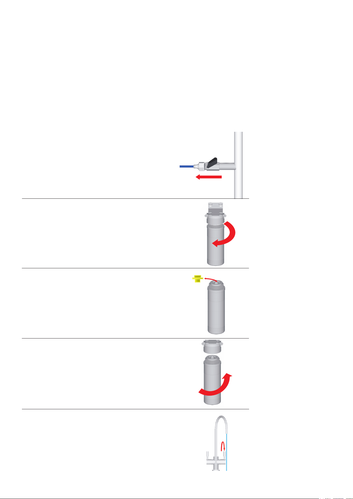
Filter Change
To ensure your Schwan drinking water system continues to provide you with
fresh filtered chilled and sparkling drinking water, your Schwan filter cartridge
needs to be replaced at least every 12 months.
In some situations where there is a lot of sedimentation or chemicals in the
water supply, it may be advisable for the filters to be replaced more frequently
to avoid annoying slow water flow or chemical taste issues.
Leave water supply ON
Filter has auto shutoff valve
1
2
3
ON
Twist old filter to the left to
remove.
Remove and discard the
yellow cap from the new
filter cartridge.
4
5
Insert new filter cartridge
into the filter head and twist
to the right until the “stop”
is reached
Run the cold water for 5
minutes to clear any air
bubbles and to condition
the filter for use.
5
Page 6
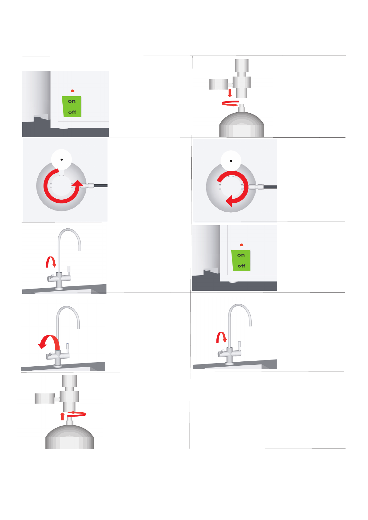
CO2 bottle replacement
1
OFF
Turn chiller off at
switch
2
OFF
Shut gas off at regulator
using control knob, turn off
gas by tuning knob
anticlockwise until it is at full
off position.
3
6
screw new CO2
bottle onto regulator
Some gas will escape
7
ON
Open regulator by turning
knob clockwise
Adjust CO2 pressure using
control knob to 4 bar.
8
ON
Bleed pressure off
at tap for 5 min
4
Shut off tap
5
Unscrew CO2 bottle
from regulator
Some gas will escape
9
Open sparkling side of tap
until sparkling water starts
to flow leave running for
10
Leave CO2 to settle for 1/2 hour
then adjust using instructions on
next page.
Turn unit back on
10 sec then shut off.
Change CO2 canister when pressure can’t be adjusted over 2 bar
6
Page 7
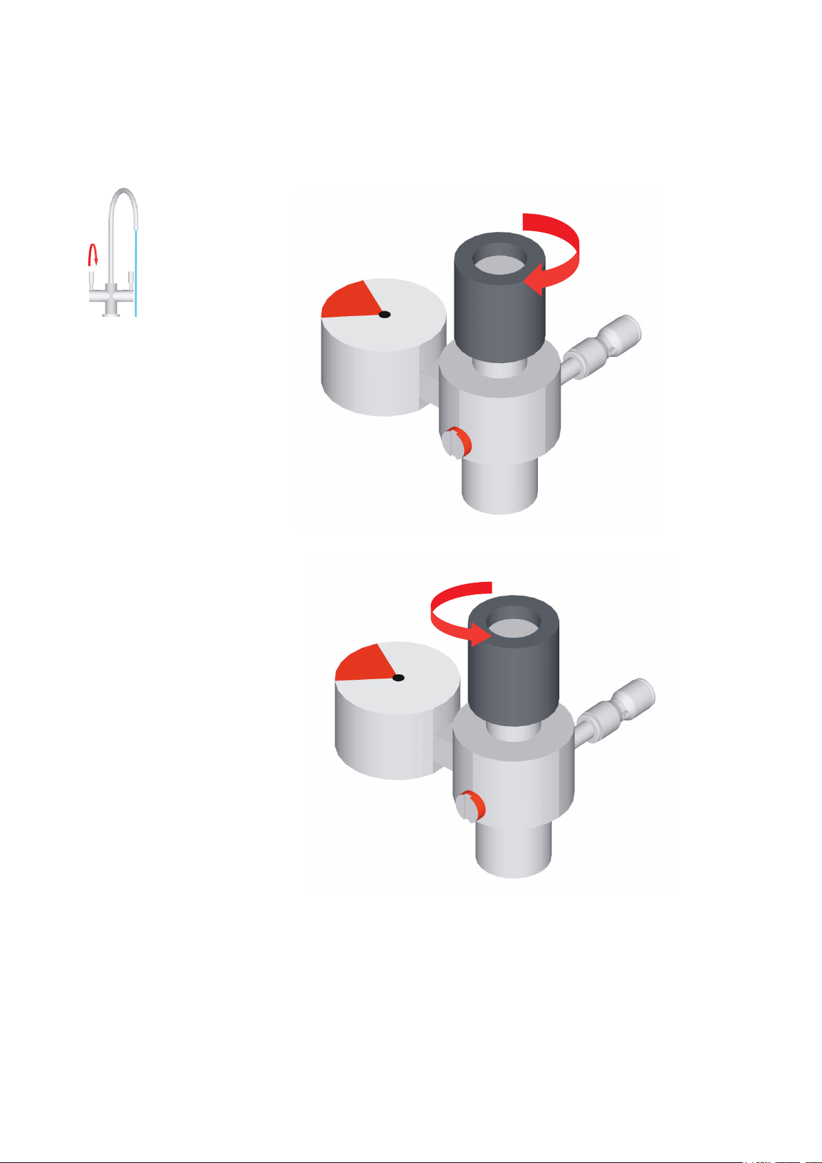
CO2 adjustment
By adjusting the knob on the regulator you can adjust the carbonation of the water. The more pressure
applied the more sparkle you get. Watch gauge on regulator and make sure the pressure doesn't ex-
ceed 5 Bar. We recommend not having the unit under 3 Bar as the unit will not produce enough sparkle.
3-5 Bar
After adjusting pressure
run tap until pump starts
then re-adjust pressure
continue process until
right setting achieved.
3-5 Bar
Pressure UP
Pressure DOWN
Pressure must not exceed 5 bar
7
Page 8
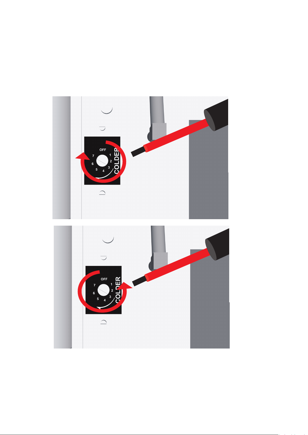
Water temp adjustment
NOTE: turning chiller on MAX chill could cause it to ice up, use MAX setting at own risk. Water
temp effects the carbonation of the sparkling water — the warmer the water the less fizz the water
will hold. The overall best setting to have chiller on is setting 6.
Water temp colder
Water temp warmer
NOTE: Use flat blade screw driver to adjust water temp
8
Page 9
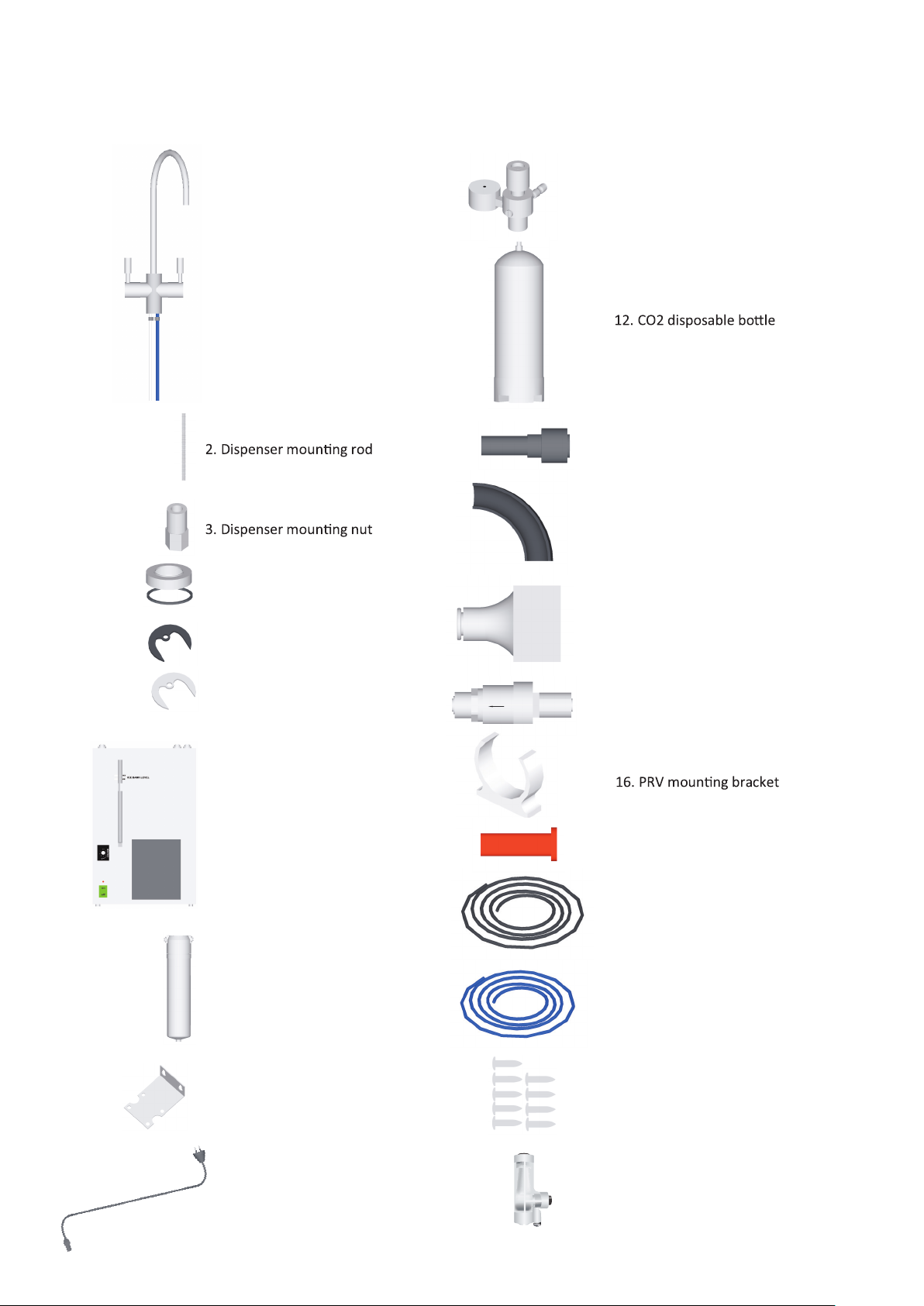
Component checklist
11. CO2 regulator
1. Dispenser with tubes
packed in separate box
13. JG reducer 8-6mm
4. Dispenser base with O-ring
5. Dispenser rubber washer
6. Dispenser metal washer
7. chiller unit
14. JG flow bend support
15. stop tap connector 1/4 inch tube
16. PRV
17. 8mm JG plug
18. 6mm co2 tube
8. Filter with filter head
9. Filter bracket
10. chiller 3 pin plug
19. 1/4 inch water supply tube
20. 20mm screws x 9
21. Soda regulator
9
Page 10
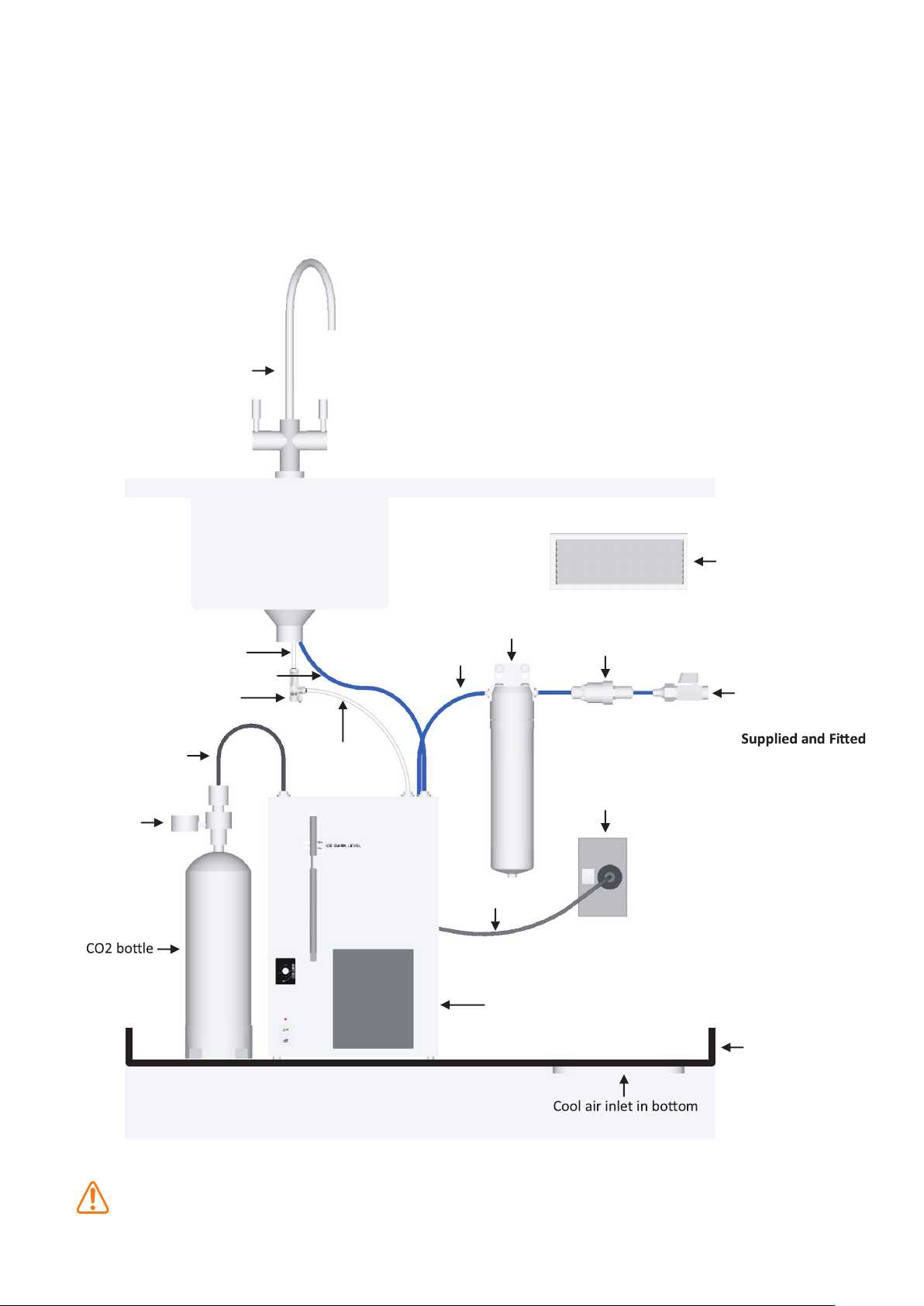
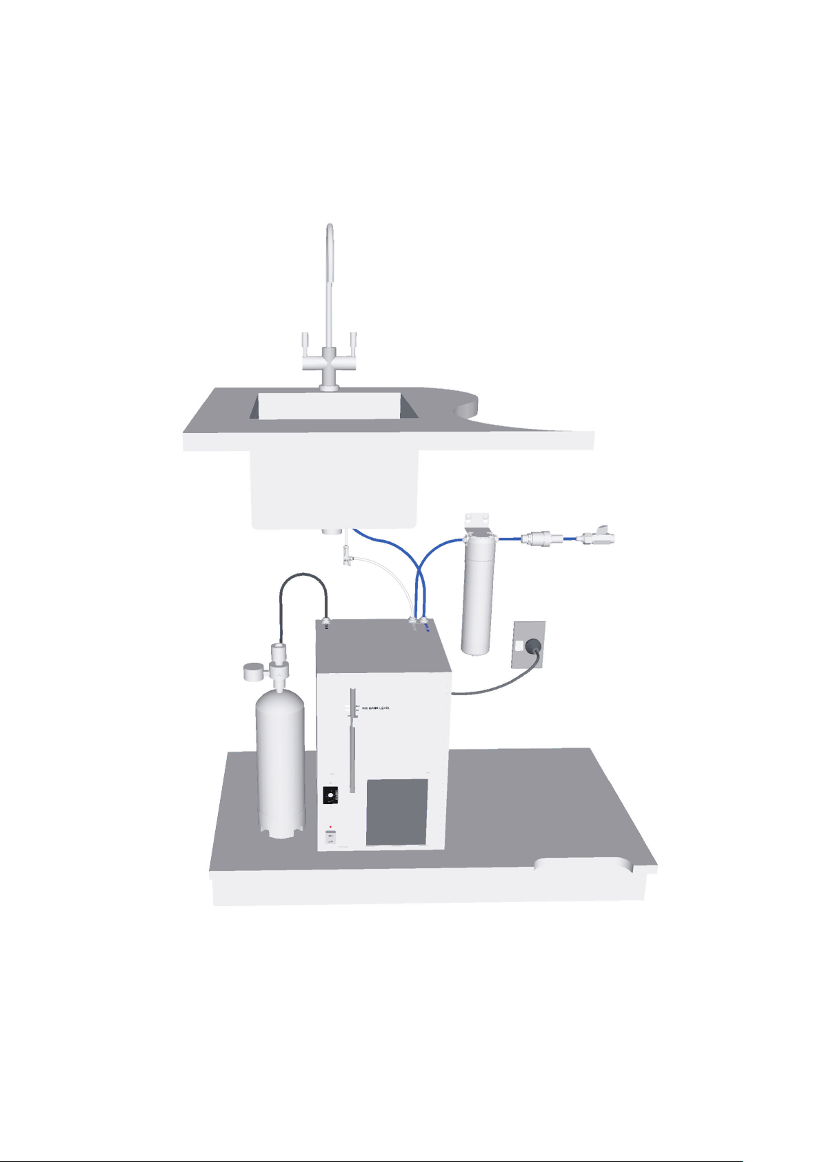
Typical installation layout
NOTE
Allow a minimum of 100mm air space around the sides,
•
back and the front of the chiller.
Cabinet must be vented to provide air flow, see venting
•
diagram on next page.
The filter system and CO2 bottle must be easily accessible
•
ine maintenance and changing.
Schwan Dispenser
for rout
The filter must be less than 600mm from the chiller inlet.
•
Use no more than 800mm of 1/4” water supply tube from
•
stop tap to chiller inlet.
Soda water to tap
white 1/4” tube
Chilled water to tap blue 1/4” tube
Soda regulator
CO2 black 6mm tube
CO2 regulator
to regulator
white 1/4” tube
cold water supply to
chiller blue 1/4” tube
Soda water
Tap base must be within 700mm of chiller outlet
•
Warm air outlet vent
in door of cabinet
Filter
system
PRV
Cold water inlet with
10 amp plug in
power supply
15mm Stop tap
by plumber
WARNING
Power cord
SC80 chiller
unit
Drained safe tray
of cabinet
In situations where any water leakage could result in damage to property, the
complete Schwan installation should be installed over a Drained Safe Tray,
plumbed to an appropriate drainage connection.
10
Page 11
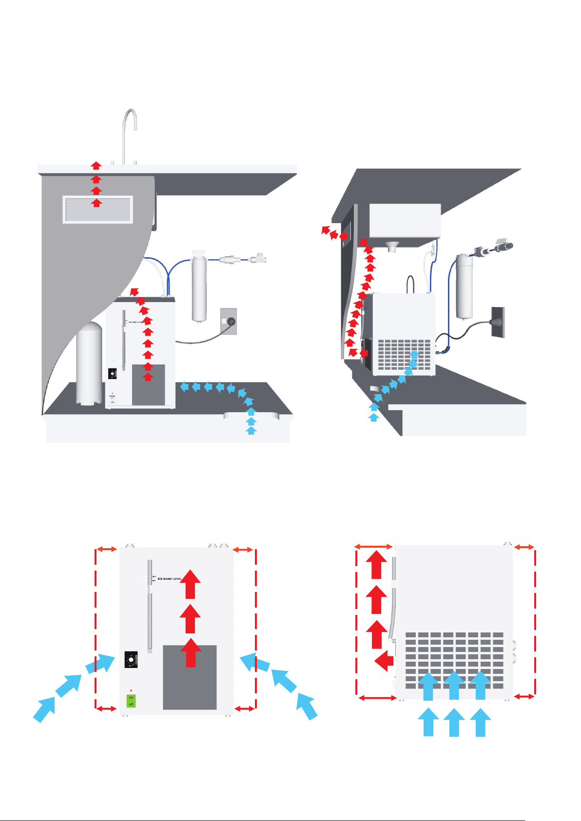
Venting requirements
Cabinet must have an air inlet vent at the bottom and outlet vent
no more than 200mm from the top
The amount of air space around the unit apply for both passive and fan forced ventilation
There must be a 100mm air space on
both sides of the under bench chiller
The front of the unit must have
at least 100mm of air space
The back of the unit needs
100mm of clearance for tubing.
11
Page 12
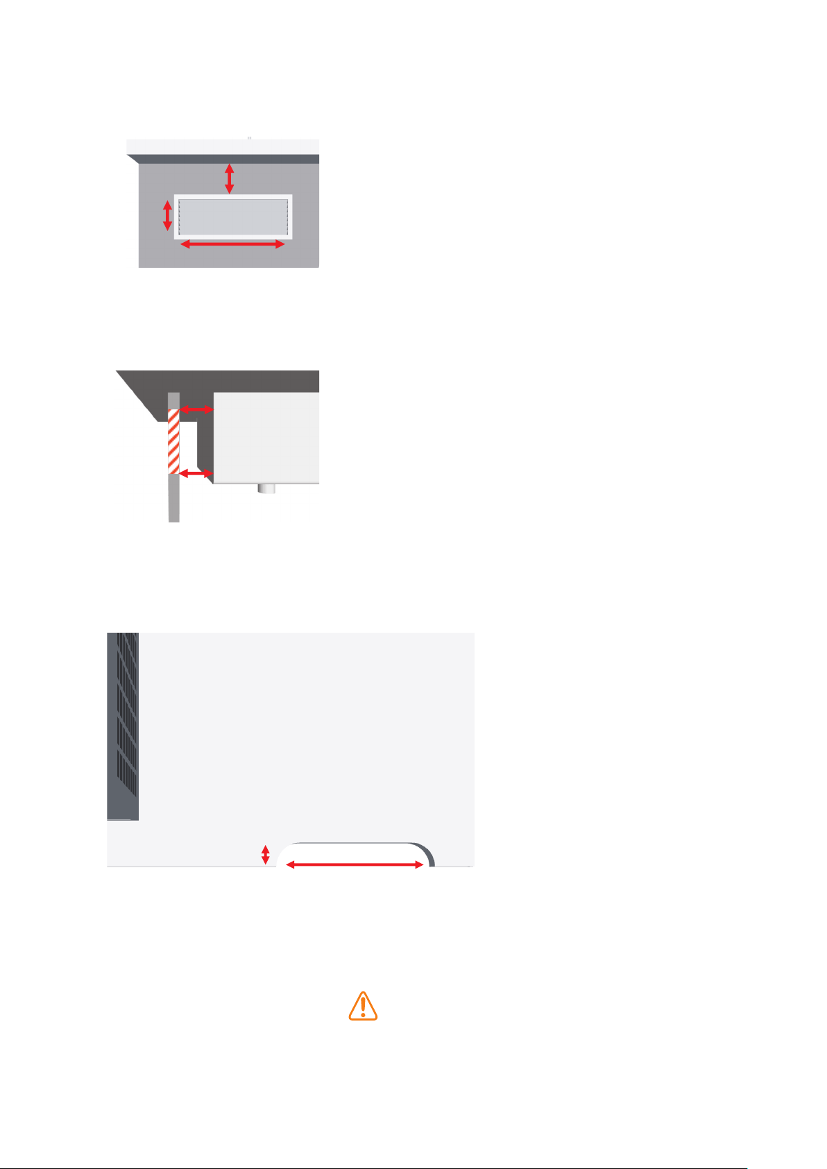
Venting requirements
Top vent must be a minimum size of
220mm x 90mm and no more than
200mm from top of door
Vent must have a minimum of
Vent
60mm of air space behind
door for air flow out of cabinet
Bottom cut out of the cabinet
must be at least 200mm x
40mm
The measurements given are the minimum sizes required to provide sufficient air flow to cool the compressor, any
less air flow and the units capacity will be effected.
If there is not enough room to place the right size vents or
the cabinet temp is reaching over 27
the cabinet will need to be vented using a fan forced system to provide enough air flow.
WARNING
12
o
C
Page 13
Installation
13
Page 14
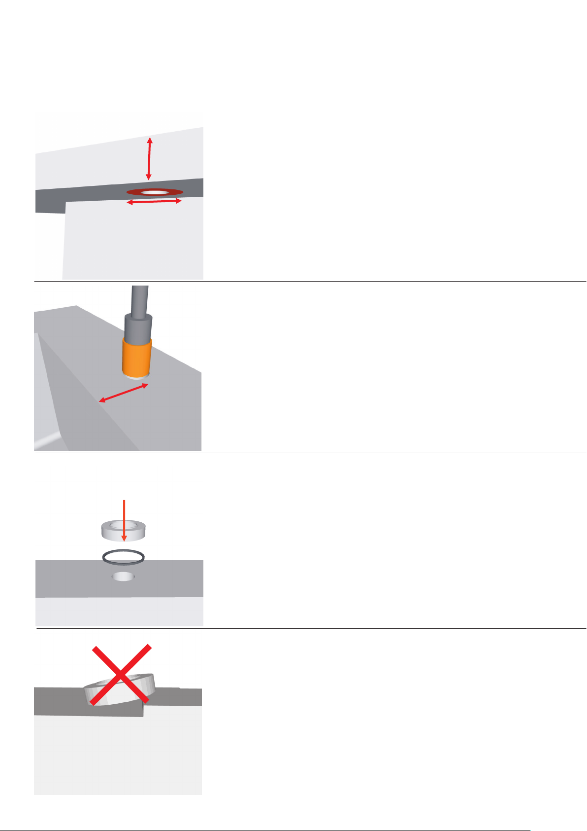
Tap install
NOTE:
The tap can not mount to a surface of more
than 30mm thick.
MAX 30 mm
Min 50 mm
MAX 80 mm
There must be a 50mm diameter flat and solid
clamping surface under the bench for the tap
mounting system
The centre of the hole must be no further than
80 mm from sink
1
Dill 25mm hole in bench top
using a hole saw.
2
3
Place tap base with washer over the
hole in the bench
Make sure bench top is flat
14
Page 15
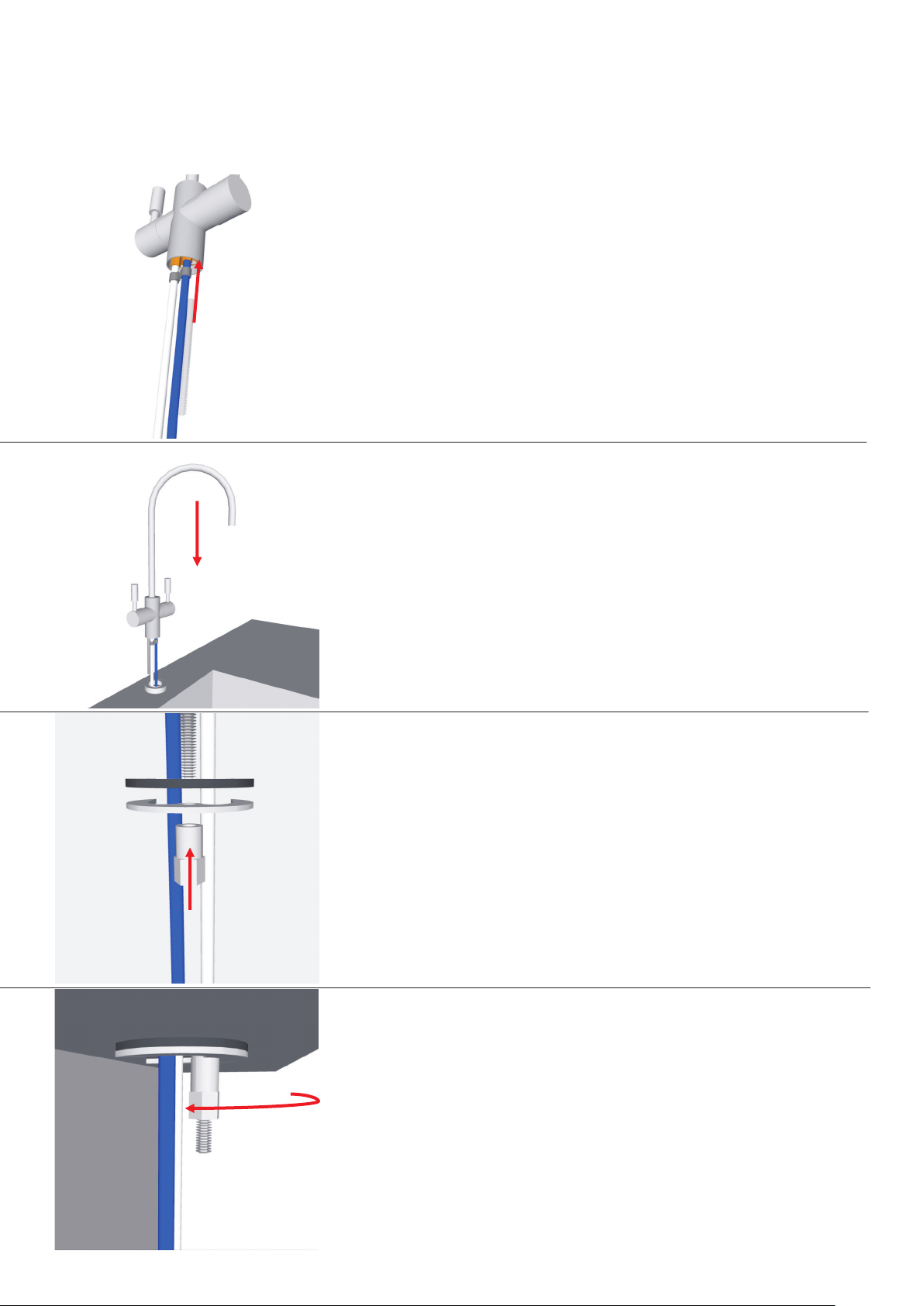
4
Screw mounting rod into bottom of
dispenser
5
6
Slide dispenser with tubes and
mounting rod into hole and sit on
tap base
Thread washers onto rod rubber first then
metal followed by nut
7
Using 13 mm tap spanner tighten nut so tap
is firmly mounted on bench
15
Page 16
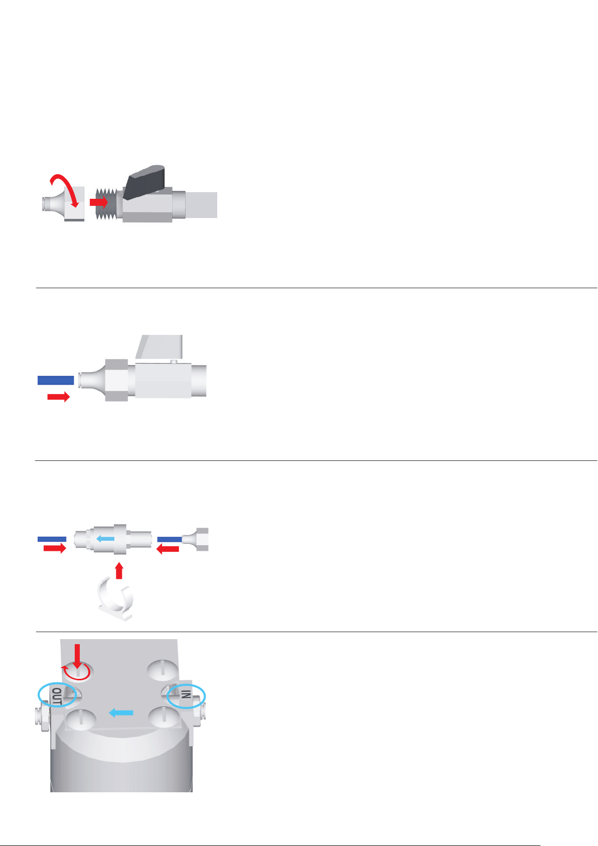
Water supply install
1
Fit 15mm to 1/4 inch adapter to stop
tap. Tighten until hand tight then give
it a light nip up with spanner.
NOTE: Do not over tighten
2
3
Fit 1/4 inch blue water supply tube to
adapter on stop tap
Press fully into connector.
Fit PRV with arrow pointing way of flow, con-
nect blue tube coming from supply to the inlet
of the Valve and connect a length of tube to
the outlet. Fasten clip to wall using one screw,
and clip PRV into place.
4
Fit bracket to filter head using 4
take note of the IN and OUT on the
head, attach bracket the appropriate
way around depending on which side
of the chiller the filter is placed on.
16
screws
Page 17
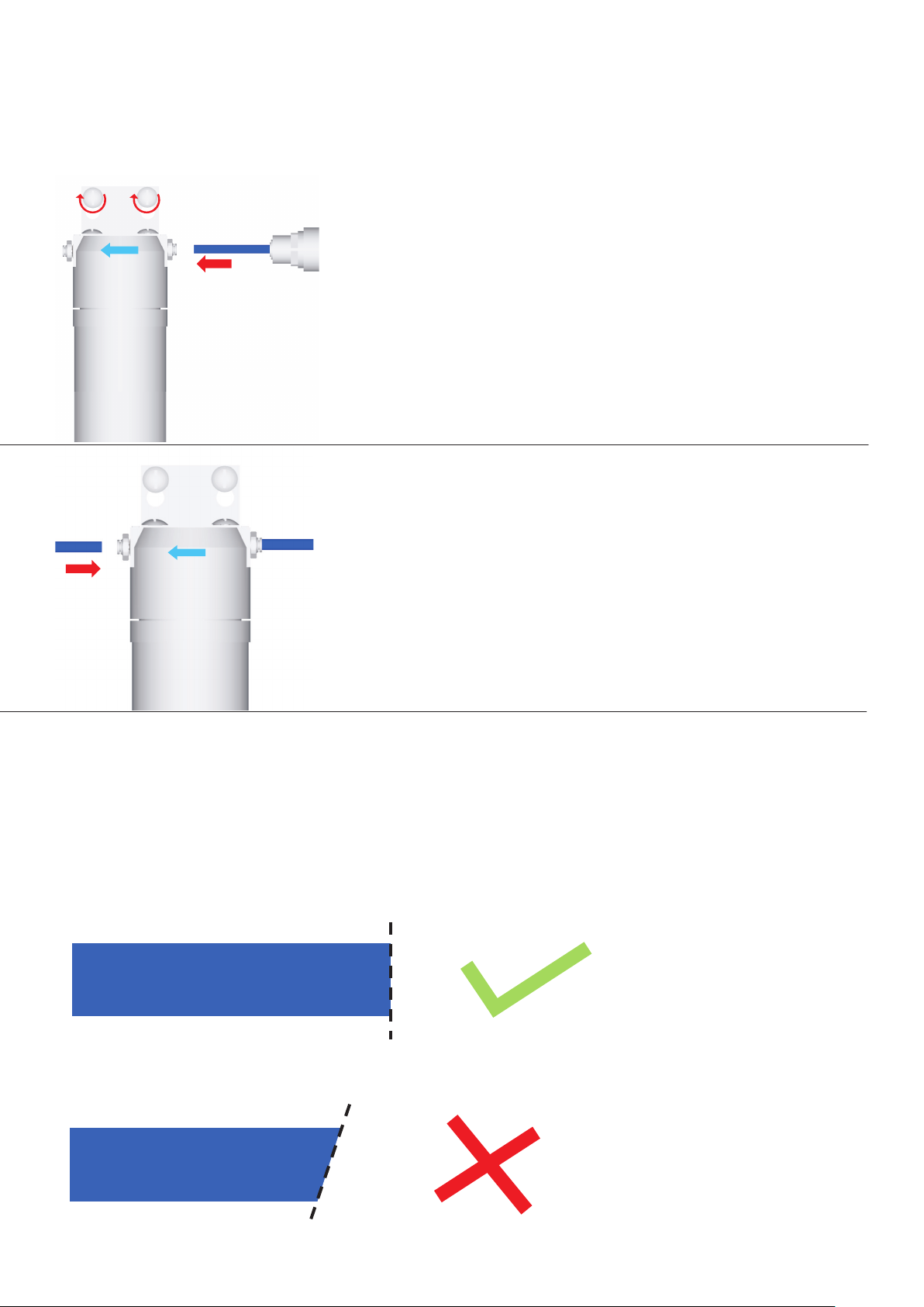
5
Using remaining 4 screws fit filter to wall.
Fit supply tube from PRV to inlet of filter
head.
NOTE: make sure that the tube is going into
the IN side of the filter head
6
Fit rest of blue 1/4 inch tube to filter outlet
Do not trim tube to length
All tubing must be cut square and clean
to fit into fittings
17
Page 18
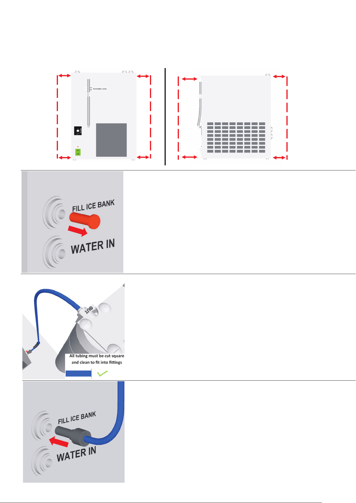
Chiller install
Unit air space clearance requirements
100MM CLEARANCE
100MM CLEARANCE
100MM CLEARANCE
100MM CLEARANCE
1
Remove ice bank plug from back of unit
2
3
Use supply tube from filter to fill ice bank
Fit tube with 8mm adapter into fill ice
bank inlet
18
Page 19
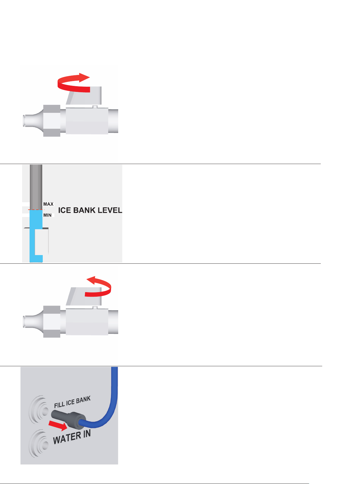
4
Open stop tap partially to provide a slow
ON
flow — do not turn on fully
5
OFF
Fill ice bank to point shown between
min and max level
6
When ice bank is full turn off water supply
7
Unplug fitting from ice bank
NOTE: some water will spill out
19
Page 20
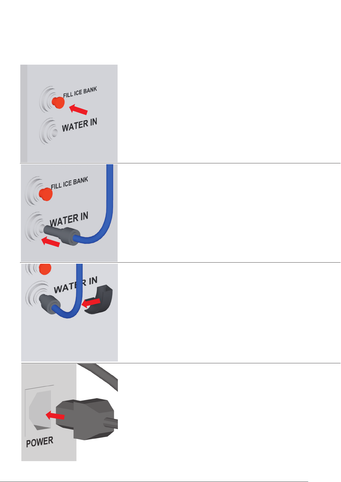
8
Put Red ice bank plug back
in to ice bank inlet
9
10
Fit water supply fitting into WATER IN
Attach flow bend clip to tube as shown
11
Plug in power cord to back of unit
20
Page 21
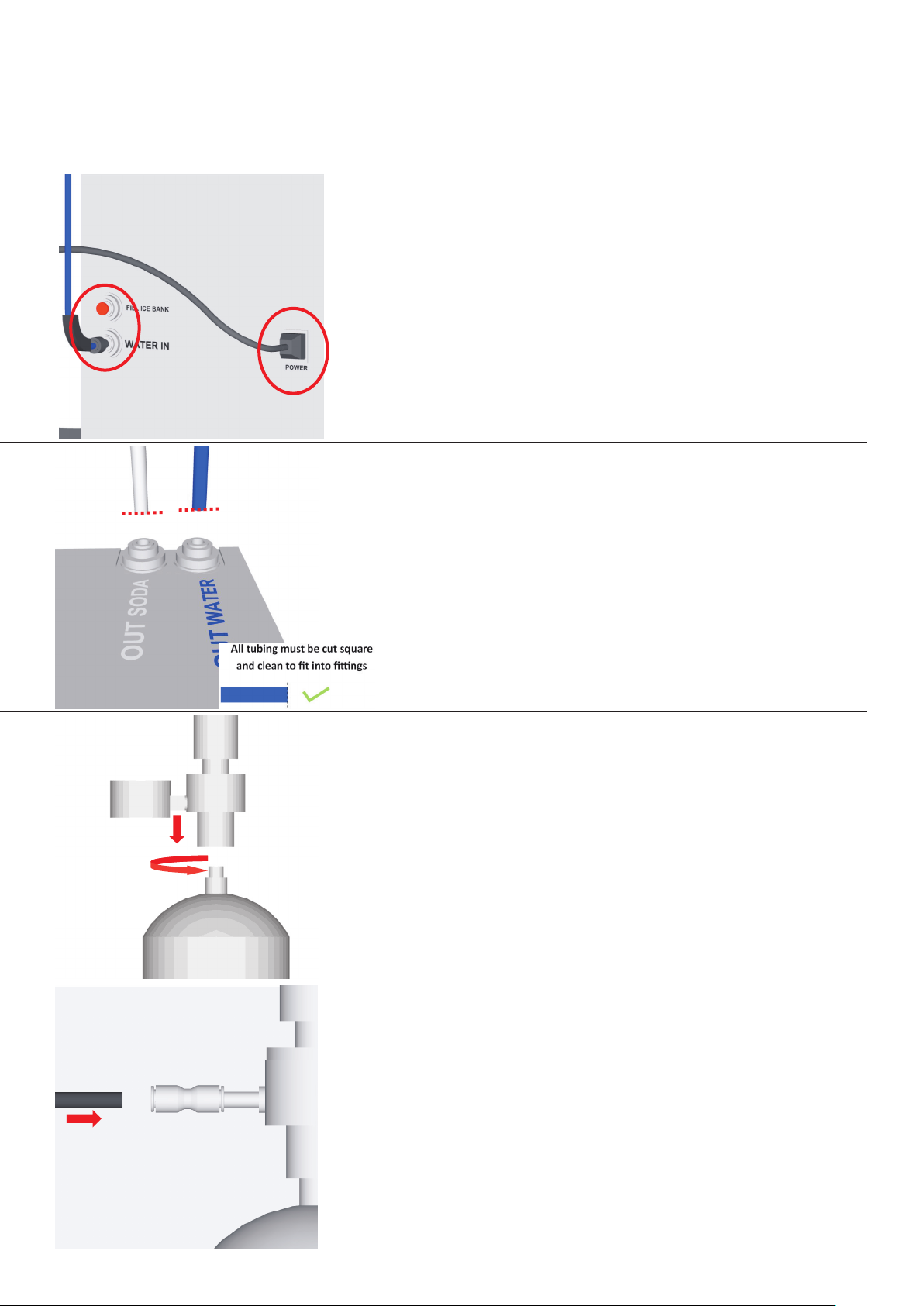
The back of the unit should look like this.
Check all fittings are in correctly and
position chiller in cabinet.
NOTE: top of internal ice bank is not sealed
take care when moving unit and dry up any
spilled water.
12
13
The tubes coming from the tap attach to the
soda out (white) and water out (blue) trim to
length.
Max distance from tap to chiller is 700mm.
Measure distance and trim tubes 100mm
longer
Attach CO2 regulator to CO2 bottle and
screw up by hand unti
Note: if gas starts coming out of regulator
once bottle is sealed turn knob anticlockwise
until flow stops.
l sealed.
14
Fit 6mm black tube to fitting on CO2 regulator
21
Page 22
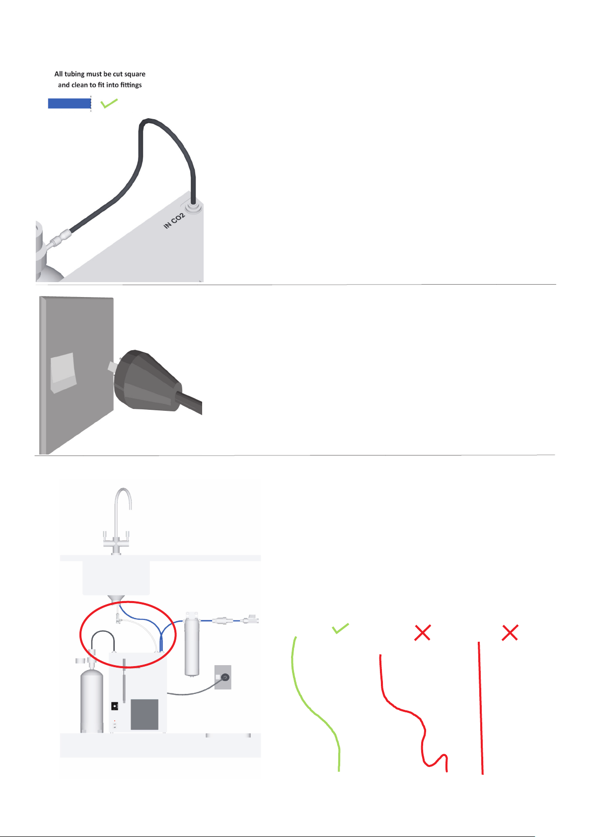
15
Position gas bottle and trim tube to
length.
Fit other end of tube to CO2 IN on the
Chiller.
OFF
16
17
Plug in 3 pin plug to power supply.
Do not turn on yet!
Tube length check
NOTE: make sure tubes are cut to
the right length to provide continuous
fall but aren’t under strain
.
Right length
22
Too long
Too short
Page 23
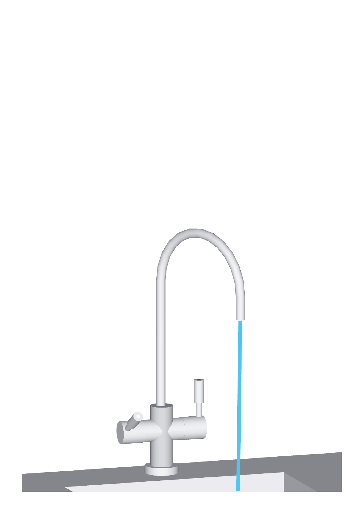
Initial setup
23
Page 24
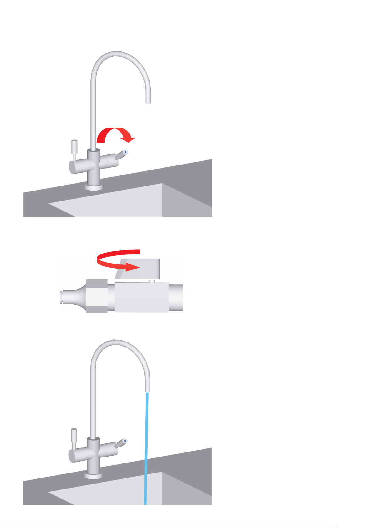
Setting up water supply
1
Open cold lever
on dispenser
2
3
Open cold water supply
slowly until fully open
Run cold water for 5 min
to clear any air bubbles
and check for leaks at
24
points shown on next
page.
Page 25
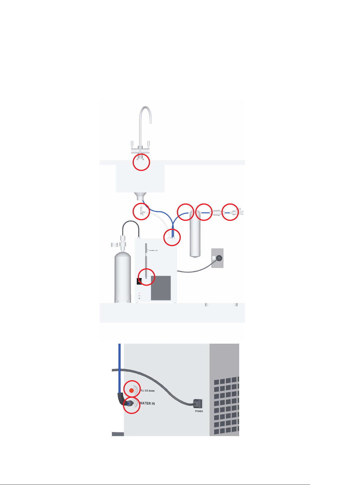
Check for water leaks
4
25
Page 26
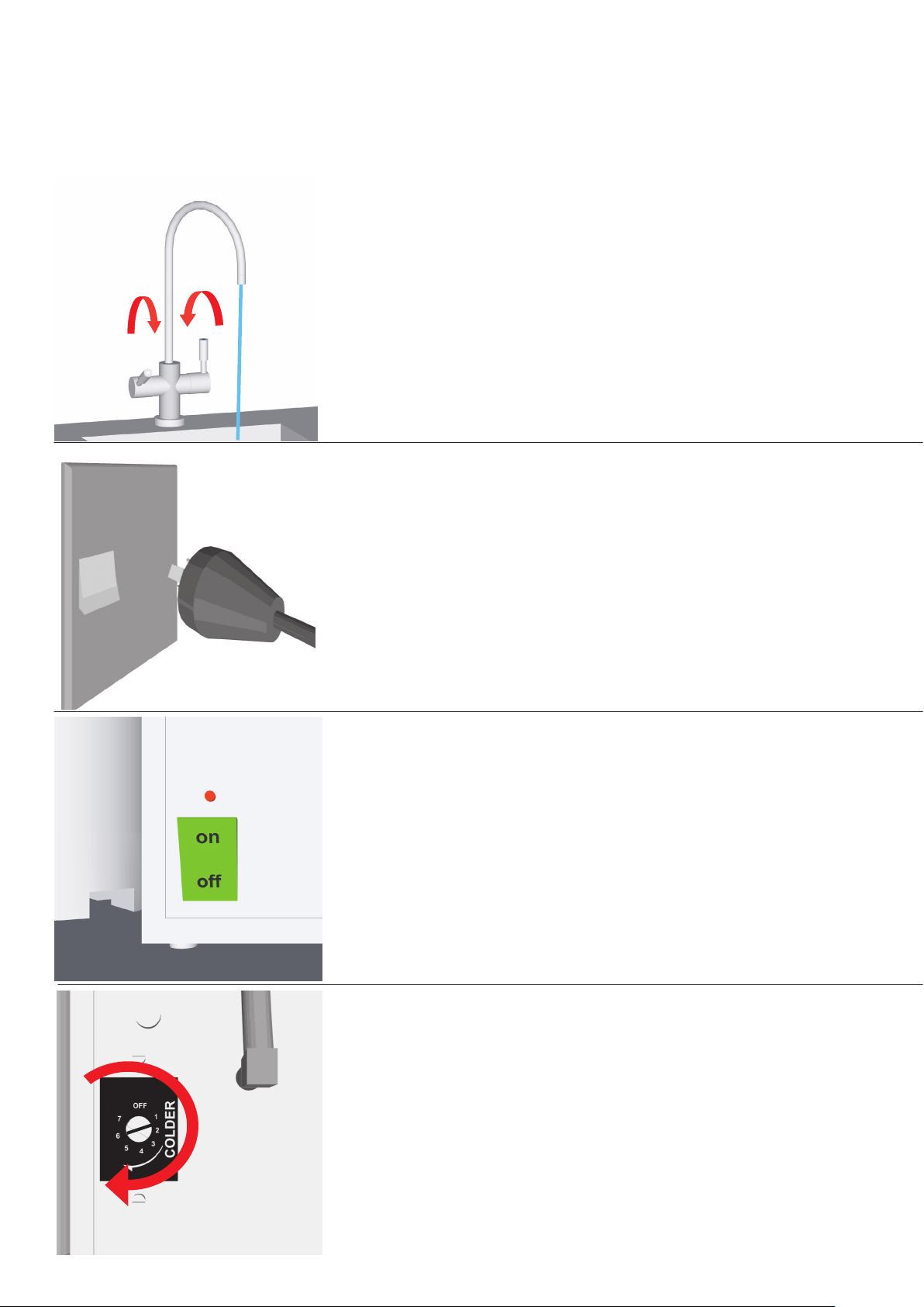
5
Close off cold water and run sparkling
side of tap to fill tank and get rid of any
air bubbles run for 5 min then shut it off
NOTE: the water on this side will come
out slow until gas is applied.
ON
ON
6
Turn power on at the wall
Socket
7
Turn power on at the unit. The
switch will light up when power
is turned on.
8
Turn on chiller and rotate chiller
temp adjuster using flat bladed
screw driver to setting 6
26
Page 27
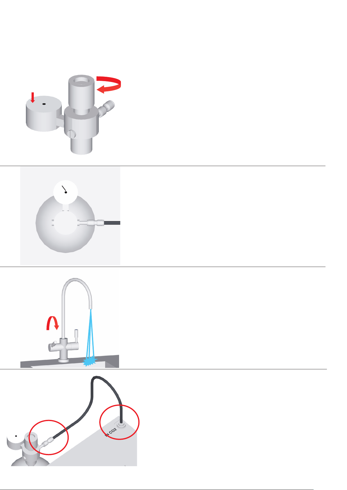
4 Bar
9
open gas regulator and set to 4 bar
4
5
3
2
6
1
7
10
NOTE: CO2 must not exceed 5 bar
11
Open soda leaver on tap 1/2 way
water will gush out open for 10
seconds. Shut off and the CO2 pump
should start up
12
Check for gas leaks
27
Page 28
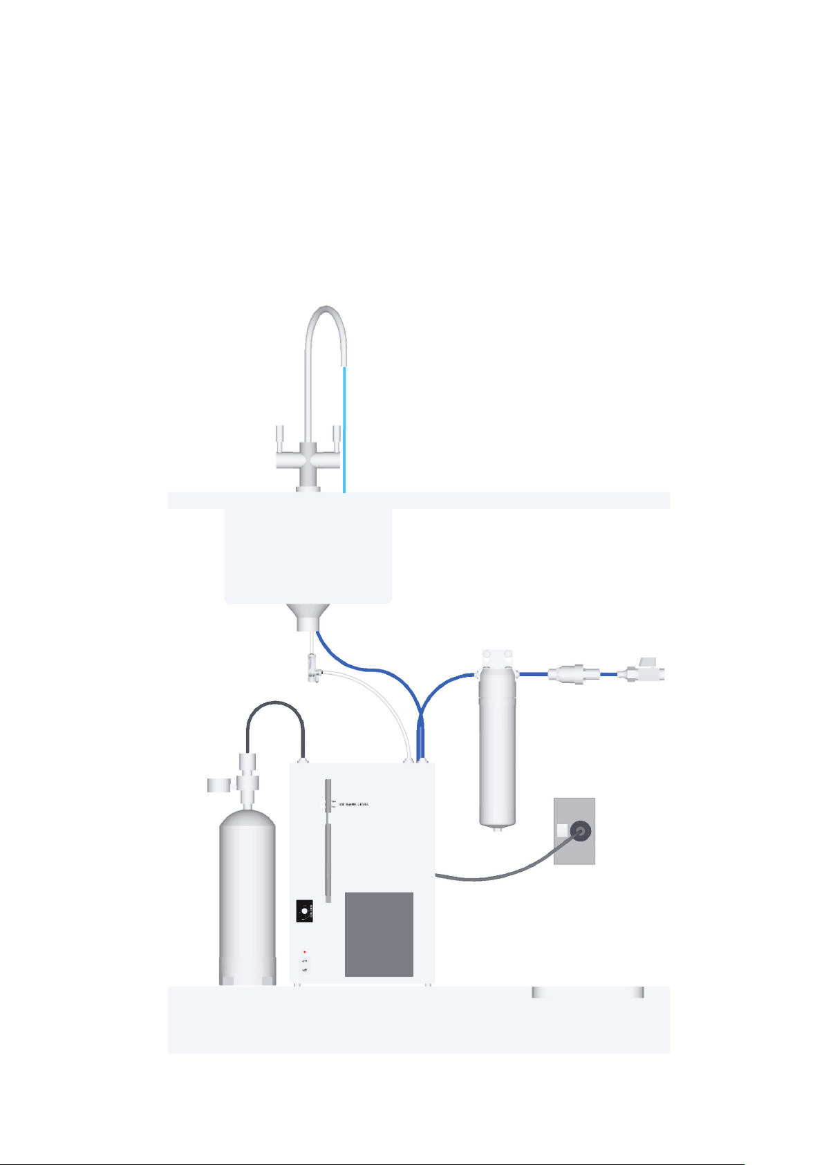
Installed unit should look like this.
28
Page 29

WARRANTY
PLEASE NOTE: As your Schwan appliance is always full of cold water,
we recommend a drained drip tray should be used in those applications
where any leakage could cause property damage.
WARRANTY PERIOD: For residential installations, the Warranty period is for two years. For commercial installa-
tions, (maximum 8 staff), the Warranty period is for one year.
Please keep all Purchase and Plumber’s installation Invoices as verification of Warranty commencement
date. The Warranty will be for 24
unable to provide proof of installation date, then the Warranty will be for 25 months (residential) or 13 months
months (residential) or 12 months (commercial) from date of installation. If you are
(commercial) from date of purchase.
WARRANTY COVERAGE: Schwan provides a comprehensive parts and labour Repair or Replacement Warranty.
Repair or Replacement will be at Schwan’s discretion, and must be carried out by an authorised Schwan Service
Agent. The Warranty covers defects in mate
your home or commercial premise free of charge during the warranty period.
However, in areas more than 25 km from an authorised Schwan Service Agent, you may be charged for some travel
Alternatively, Schwan may require you to return your unit to Schwan so that Schwan can provide you with a replace-
ment unit free of charge. In this case, Schwan will pay the necessary freight charges, and you wi
sponsibility for the removal of the faulty unit, and installation of the replacement unit.
Any product replaced or repaired under this Warranty will be covered by the remaining portion of the original
product’s Warranty period, or 6 months, whichever is the greater.
WARRANTY EXCLUSIONS: This Warranty does not cover damage, deterioration, or malfunction resulting from ac-
cident, misuse, neglect, abuse, unauthorised modification, fire, water, lightning or other acts of nature
stallation, poor water quality, repair or attempted repair by anyone other than an authorised Schwan Service Agent,
or external causes such as electric power fluctuation or failure.
Filter cartridges are not covered by this Warranty, as these are a consumable item, and water conditions and usage
vary, which can affect the effective life of the filter.
LEGISLATION: Nothing in this Warranty overrides Schwan’s responsibilities under the Consumer Guarantees Act
for residen
tial installations. The owner agrees that the Consumer Guarantees Act does not apply to commercial in-
rials and manufacturing only, and repairs will normally be carried out in
and associated costs.
ll need to take re-
, incorrect in-
stallations.
IN THE EVENT OF A MALFUNCTION, PLEASE CONTACT MERQUIP ON 0800 636 0 636 OR
EMAIL se[email protected]
MODEL: SC80
SERIAL NUMBER:
29
Page 30
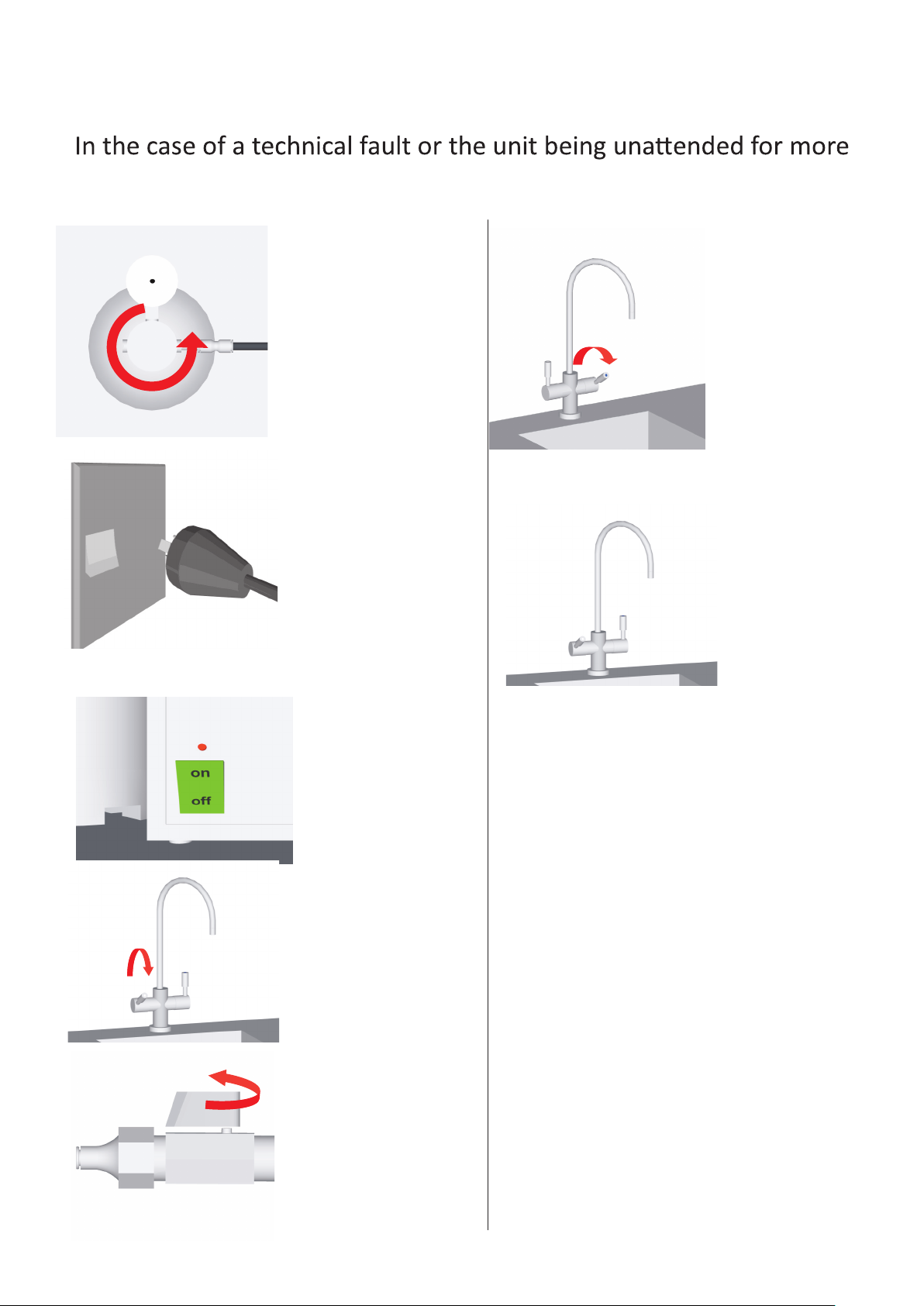
Unit shutdown
than 24 hours shut down unit by following these steps
1
OFF
Shut gas off at regulator
using control knob, turn off
gas by tuning knob
anticlockwise until it is at full
off position.
2
6
Open cold tap
until water stops
flowing
OFF
Turn power off at
the wall
3
OFF
4
Turn chiller off at
switch
Bleed pressure off
sparkling at tap for
5 min
7
Leave sparkling
side of tap open
5
Turn off water
supply at stop tap
To restart unit follow
steps in reverse.
30
Page 31
NOTES
This unit is backed by MERQUIP
For service call 0800 636 0 636
Or visit www.merquip.co.nz
And book a service
31
Page 32

 Loading...