

Schwaiger DiSEqC Multiswitch Installation Information

Montagehinweis zum DiSEqC-Multischalter
V
H V
H
V H
V H
TV / FM
1210
14
16
13
15
11
9
42 6
8
V
42 6
8
H V
H
5 7
3
1
V H
V H
TV / FM
1210
14
16
13
15
11
9
9 auf 4/8/12/16 mit Energiespar-Modus

2
Montagehinweise zum DiSEqC-Multischalter
Der Multischalter ermöglicht die Verteilung analoger und digitaler Signale von zwei
Satellitensystemen bzw. acht Empfangsebenen.
Er hat zusätzlich die Option, terrestrische Kanäle einzuspeisen, um z.B. UKW oder regionale analoge oder digitale (DVB-T) Fernsehprogramme ins TV-Netz mit aufzunehmen.
WICHTIG : Vor Inbetriebnahme des Multischalters die Bedienungsanleitung
vollständig durchlesen und die Sicherheitshinweise beachten.
1.0. Begriffserklärungen
analoge Kanäle:
= „unteres“ bzw. „low“ Frequenzband (Frequenzbereich: 10,70 - 11,70 GHz)
digitale Kanäle:
= „oberes“ bzw. „high“ Frequenzband (Frequenzbereich: 11,70 - 12,75 GHz)
vertikale Polarisationsebene (V) : DC-Spannung typ. +14 V
horizontale Polarisationsebene (H) : DC-Spannung typ. +18 V
Kennfrequenz 22 kHz :
Die Kennfrequenz 0/22 kHz wird zum Umschalten von LNB1/low-Band auf
LNB1/high-Band verwendet.
DiSEqC : Digital Satellite Equipment Control (sprich : Dai-Säck)
Tone-Burst (auch Simple-DiSEqC oder Mini-DiSEqC genannt):
Der Tone-Burst ist neben den 14/18V zur Polarisationsumschaltung und den
0/22kHz zur Frequenzbandumschaltung ein weiteres Schaltkriterium zur Umschaltung
zwischen zwei SAT-Positionen (LNB1/LNB2).
DiSEqC Level 1.0:
• „One-Way“-Bus-Protokoll arbeitet mit dem kompletten DiSEqC-Befehlsatz
DiSEqC Level 2.0:
• „Two-Way“-Bus-Protokoll arbeitet mit dem kompletten DiSEqC-Befehlsatz
Energiespar-Modus:
• siehe 3.3
2
2.0. Steuerung des Multischalters
Die Steuerung des Multischalters kann entweder über die bekannten analogen
Schaltkriterien oder über DiSEqC-Befehle erfolgen.
-
Bei Ansteuerung des Multischalters mit den bekannten analogen Schaltkriterien kann
auf max. zwei Frequenzbänder zugegriffen werden (LNB1/low - LNB1/high).
-
Bei Ansteuerung des Multischalters mit DiSEqC-Befehlen kann auf alle vier
Frequenzbänder zugegriffen werden.
(Multischalter-Gruppenadresse: 10H/ Multischalter-Direktadresse: 14H)
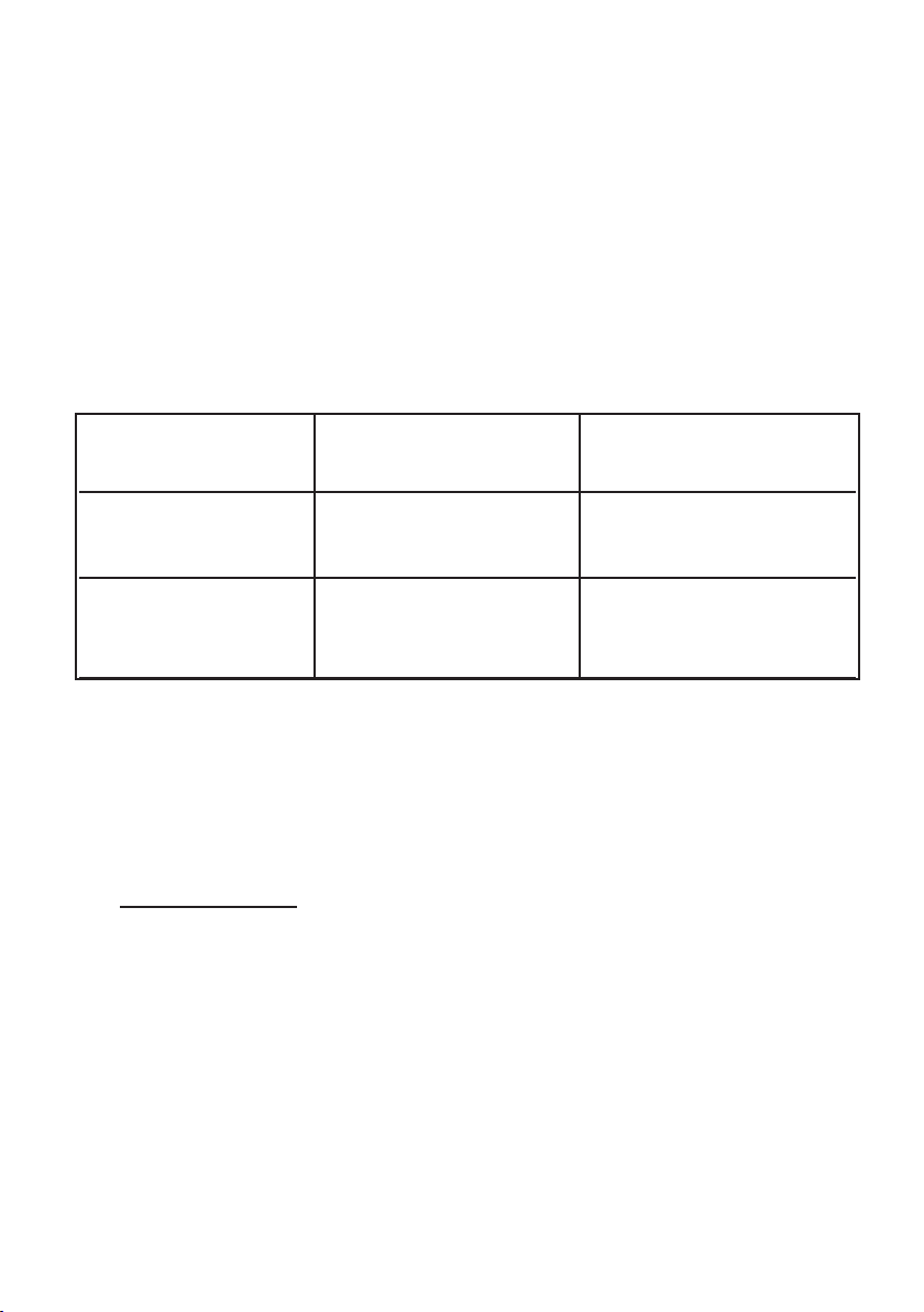
eingesetzter Schalt- Bemerkung
Receivertyp kriterium
Tone-Burst-Receiver Tone-Burst Bsp.: Empfang von
ASTRA analog/digital
Eutelsat analog/digital
DiSEqC-Receiver DiSEqC-Befehle Bsp.: Empfang von
Level 1.0 oder 2.0 ASTRA analog/digital
Eutelsat analog/digital
3.0. Installationshinweise
Bitte beachten Sie die gültigen Sicherheitsbestimmungen!
(siehe auch beiliegendes Merkblatt „Wichtige Sicherheitshinweise“)
3.1. Speisesysteme / LNBs
Als Speisesyteme zum Empfang analoger und digitaler Programme aus zwei SAT-
Positionen können zwei Universal-Quattro-LNBs (z.B. Schwaiger SPS 6918) eingesetzt
werden. Für den Empfang analoger Programme aus vier SAT-Positionen sind vier TWIN LNBs (z.B. Schwaiger SPS 6914) an den Multischalter anzuschließen.
WICHTIG :
Bei Verwendung anderer LNB-Typen ist auf deren Strombedarf zu achten
(siehe 3.2.)!
3
3

4
3.2. Spannungsversorgung der LNBs
Die Spannungsversorgung der LNBs erfolgt über das Netzteil am Multischalter.
Zur LNB-Speisung stehen je LNB max. 600 mA zur Verfügung.
=> Insgesamt steht zur Versorgung der LNBs max. 1,2 Ampere zur Verfügung.
3.3 Energiespar-Modus
Der Multischalter verfügt über eine Stromsparschaltung (Standby).
Die LNBs werden nicht mit Spannung versorgt, solange kein Receiver ein geschaltet ist.
In diesem Zustand nimmt der Multischalter nur eine geringe Leistung auf.
Der terrestrische Verstärker bleibt davon unberührt, d.h. UKW- und
Fernsehempfang über Antenne sind weiterhin gewährleistet.
3.4. Anlagenverkabelung
- Der Anlagenaufbau muß eine sternförmige Verteilstruktur vom Multischalter zu den
Antennensteckdosen (z.B. Schwaiger DSE 650 bzw. DSE 652) aufweisen, d.h. an jeden
Ausgang des Multischalters darf nur ein Receiver angeschlossen werden, für Twin-
Receiver werden zwei Zuleitungen benötigt.
- Zur Anlagenverkabelung 75 Ohm Koaxialkabel (z.B. Schwaiger KOX 110) einsetzen.
- Nach Montage der F-Stecker Koaxialkabel auf Kurzschlüsse überprüfen.
3.5. Es wird empfohlen, alle nicht benützten Ein- und Ausgänge des Multischalters mit
kapazitiv getrennten 75 Ohm Abschlußwiderständen (z.B. Schwaiger ÜST 8380 201)
abzuschließen.
3.6. Montage des Multischalters
Die Montage des Multischalters ist nur in trockenen Räumen,
bei ausreichender Belüftung zulässig.
Der Montageuntergrund muß schwer entflammbar sein.
WICHTIG :
Der Multischalter erwärmt sich im Dauerbetrieb bei 25°C Zimmertemperatur
stellenweise auf bis zu 55°C, je nach Stromaufnahme des verwendeten LNB-Typs.
3.7. Schutzmaßnahme
Erdung des Multischalters über dessen Erdungsklemme!
4

4.0. Technische Daten
E
n
e
r
g
i
e
-
S
p
a
r
-
M
o
d
u
s
E
n
e
r
g
y
S
a
v
i
n
g
M
o
d
e
Gerät
9 auf 4/8/12/16
Anzahl der Ausgänge 4 / 8 / 12 / 16
Anschlüsse F
SAT
Anzahl der Eingänge 8
Frequenzbereich 950 - 2150 MHz
Durchgang typ. 1dB
Eingangs - Entkopplung typ. 30dB
EN 50083-3 (35dB) typ. 100 dBµV
RDF/TV
Anzahl der Eingänge 1
Frequenzbereich 47- 862 MHz
Durchgang typ. 6 / 2 / -2 / -2 dB
EN50083-3 (60dB) typ. 92 / 87 / 83 / 83 dBµV
Eigenstromaufnahme vom Receiver typ. 65 mA
Stromversorgung für LNB max. 1,2 A
Netzanschluß 230 V / 35 Watt max.
Abmessungen 298 / 368 / 438 / 508 x 142 x 72 mm
Für weitere Fragen stehen wir Ihnen gerne zur Verfügung.
Technische Auskunft: Telefon : +49 (0) 91 01/ 702-299
Christian Schwaiger GmbH
DiSEqC ist ein eingetragenes Warenzeichen von EUTELSAT Technische Änderungen und Irrtümer vorbehalten.
55

6
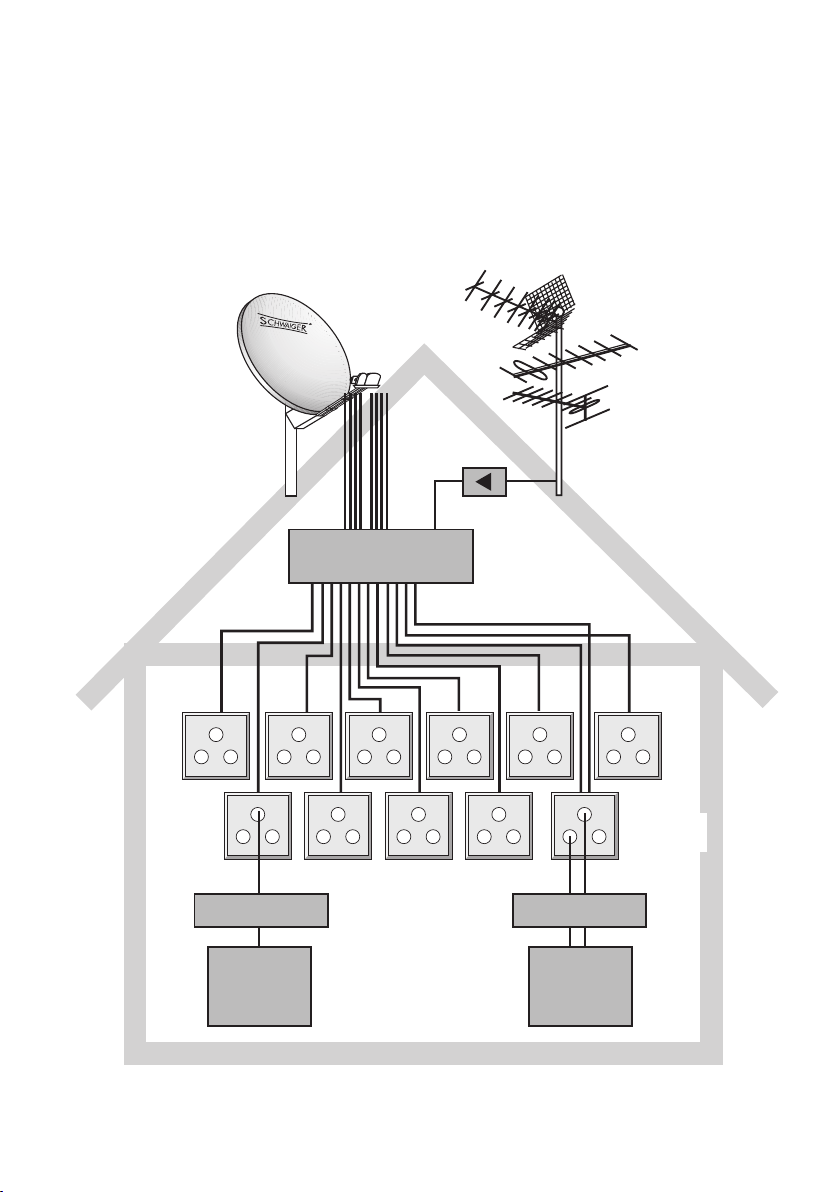
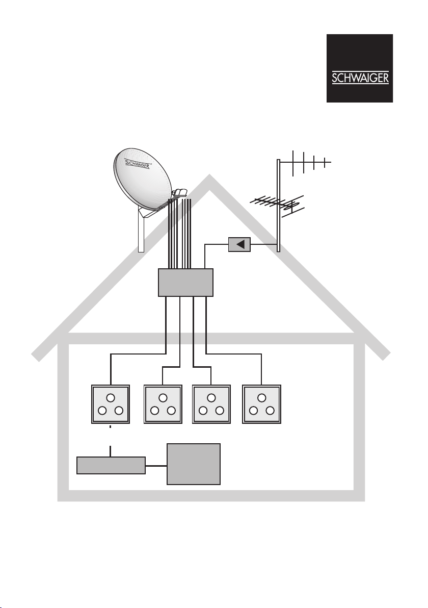
Anwendungsbeispiel
Mehrteilnehmeranlage mit DiSEqC - Multischalter SEW 9xx
SPI 900
2x SPS 6918
1x UHA 60
DSE 650
Receiver
SEW 9xx
DSE 650 DSE 650
TV
DVB-T
UKW
BNT 2569
DSE 650
6
UHF
SPI 1000
2x SPS 6918
1X UHA 100
DSE 650
VHF
UKW
BN 2338
SEW 9xx
DSE 652
Receiver Twin-Receiver
TV TV
77

8
42 6
8
V
42 6
8
H V
H
5 7
3
1
V H
V H
TV / FM
12
10
14
16
13
15
11
9
Installation information for the
V
H V
H
V H
V H
TV / FM
1210
14
16
13
15
11
9
4
2 6
8
V
4
2 6
8
H V
H
5 7
3
1
V H
V H
TV / FM
12
10
14
16
13
15
11
9
DiSEqC Multiswitch 9 in 4/8/12/16 out
with energy-saving mode
9

10
DiSEqC Multiswitch - Mounting Instructions
The multiswitch serves for analog and digital reception of two satellite systems or eight frequency levels.
It provides the option to feed in terrestrial channels, e.g. in order to integrate FM radio stations
or local analog oder digital (DVB-T) TV stations into the TV network.
HINT: Please read the operating instructions carefully and be aware to observe
all security hints before starting your multi-switch system.
1.0. Explanation of the terms used in the Mounting Instructions
Analog channels:
= „low“ frequency band (frequency range : 10.70 - 11.70 GHz)
Digital channels:
= „high“ frequency band (frequency range : 11.70 - 12.75 GHz)
Vertical plane of polarization (V) : DC voltage typ. +14 V
Horizontal plane of polarization (H) : DC voltage typ. +18 V
Characteristic frequency 22 kHz :
The 0/22 kHz characteristic frequency is used
for switching from the LNB1/low band to the LNB1/high band.
DiSEqC := Digital Satellite Equipment Control
Tone burst (also called Simple DiSEqC or Mini DiSEqC) :
In addition to the 14/18 V option used for polarization switching and the
0/22 Hz option used for frequency band switching, the tone burst is a further option for
switching between two SAT positions (LNB1/LNB2).
DiSEqC Level 1.0:
The „one way“ bus protocol uses the complete DiSEqC command set.
DiSEqC Level 2.0:
The „two way“ bus protocol uses the complete DiSEqC command set.
Energy saving mode:
• see 3.3
10
2.0. Multiswitch Control
The multiswitch can be controlled either by way of the usual analog switching media or by way
of DiSEqC commands.
- Activating the multiswitch by means of the usual analog switching media provides
access to max. two frequency bands. (LNB1/low - LNB1/high)
- Activating the multiswitch by means of the DiSEqC commands provides access to all four
frequency bands (group address of the multi-switch= 10 H/ direct address of the multiswitch=14H).
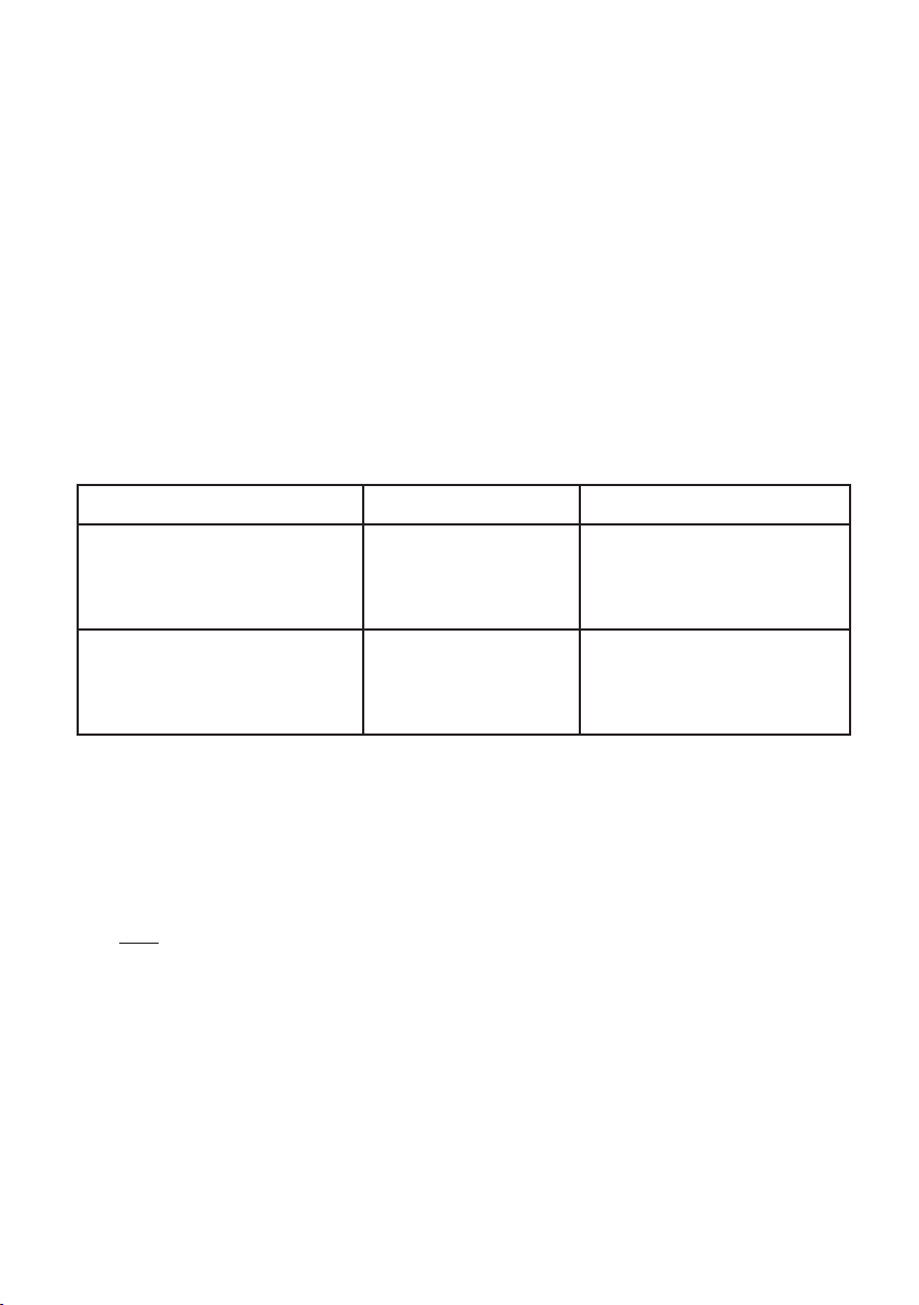
Type of receiver applied Switching method Remark
Tone burst receiver
Tone burst
Example: Reception of
ASTRA/analog/digital
Eutelsat/analog/digital
DiSEqC receiver level 1.0 or 2.0 DiSEqC commands
Example: Reception of
ASTRA/analog/digital
Eutelsat/analog/digital
3.0. Installation Instructions
The currently valid safety requirements must be observed!
(See enclosed sheet of instructions „Important Safety Hints“)
3.1. LNBs
Two Universal Quattro LNBs can be used as input systems for the reception of analog and
digital programs from two SAT positions (e.g. Schwaiger SPS 6918).
In order to receive analog programs from four SAT positions, four TWIN LNBs
(e.g. Schwaiger SPS 6814) must be connected to the multiswitch.
HINT :
When using other LNB types, be aware of their current demand!
(see chapter 3.2. of these instructions)
11
11

12
3.2. LNB Power Supply
The power supply of the LNBs is performed by means of the power supply unit at the
multiswitch. A maximum of 600 mA per LNB is available to feed the LNBs
=> Max. 1,2 Ampere are available for power supply of the LNBs.
Low energy consumption
3.3
If all connected satellite receivers are turned off, the multiswitch enters a
power saving standby mode, where the LNB supplies and the satellite
amplifiers are disabled. The LNBs are not supplied with power unless at least
one of the receivers is switched on. The terrestrial reception with its amplifiers is not
affected.
System Cabling
3.4.
- T3.4 The system must have a star-topology distribution structure from the multiswitch to
the antenna sockets (e.g. Schwaiger DSE 650 or DSE 652) , i.e. only one receiver may be
connected to each output on the multiswitch. For twin receivers you need two supply lines.
- Use 75 Ohm coaxial cables for system cabling (e.g. Schwaiger KOX 110).
- Subsequent to mounting the F connectors, check the coaxial cables for short circuits.
3.5. All unused inputs and outputs of the multiswitch should be terminated capacitively separa ted 75 Ohm matching resistors (e.g. Schwaiger ÜST 8380 201).
3.6. Mounting of the Multiswitch
Multiswitches must only be installed in dry rooms with sufficient ventilation.
Moreover, multiswitches must be mounted to a hardly flammable ground.
IMPORTANT:
During constant operation at 25°C room temperature, some parts of the multiswitch carry a
temperature of up to 55°C, depending on the current input of the LNB type used.
3.7. Protective Arrangement
The multiswitch needs to be grounded by way of its grounding terminal!
12
4.0. Technical Data
E
n
e
r
g
i
e
-
S
p
a
r
-
M
o
d
u
s
E
n
e
r
g
y
S
a
v
i
n
g
M
o
d
e
Product 9 in 4/8/12/16 out
Number of outputs 4 / 8 / 12 / 16
Connections F
SAT
Number of inputs 8
Frequency range 950-2150 MHz
Transmission typ. 1 dB
H/V isolation typ. 30 dB
EN 50083-3 (35dB) typ. 100 dBµV
RDF/TV
Number of inputs 1
Frequency range 47-862 MHz
Transmission typ. 6 / 2 / -2 / -2 dB
EN 50083 - 3 (60dB) typ. 92 / 87 / 83 / 83 dBµV
Induced current input from receiver typ. 65 mA
Power supply for LNB max. 1,2 A
Power supply 230 V / 35 Watt max.
Dimensions 298 / 368 / 438 / 508 x 142 x 72 mm
For further questions, please do not hesitate to contact us.
Our hotline for technical information : +49 (0)9101 / 702-299
Christian Schwaiger GmbH
DiSEqC is a registered trade mark of EUTELSAT Subject to change without prior notice. / Errors excepted.
13
13
14
Example of use
Multi-user system with DiSEqC multiswitch SEW 9xx
SPI 900
2x SPS 6918
1x UHA 60
DSE650
Receiver
DVB-T
UKW
BNT 2569
SEW 9xx
DSE650 DSE650 DSE650
TV
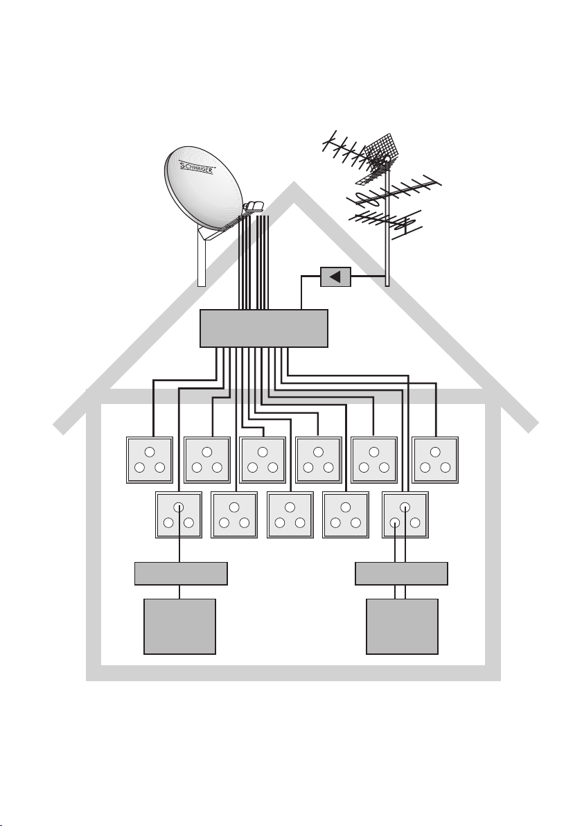
UHF
SPI 1000
2x SPS 6918
VHF
UKW
1X UHA 100
BN 2338
SEW 9xx
DSE650 DSE652
Récepteur
Twin receiver
TV
TV
15
15
 Loading...