


www.schurter.com
123
Produktebeschreibung
Der AS168X ist ein thermisch magnetischer Hochleistungs CBE, der
in der Lage ist, bei Kurzschluss-Abschaltungen den Durchlass-Strom
drastisch zu reduzieren. Die Serie ist erhältlich in Ausführungen mit
einem bis vier geschützten Polen, die in Wechselstrom- oder Gleichstromnetzen eingesetzt werden können. Mehrpolige CBE sind intern
und beim Kipphebel mechanisch verbunden, um gleichzeitiges Schalten zu gewährleisten. Dies gilt auch für eine Kombination mit dem
schaltbaren Null-Leiter Pol. Raffiniert konstruierte Liftklemmen auf der
Eingangs- und Abgangsseite ermöglichen einen bequemen Netz- und
Lastanschluss. Die Klemmen sind zum Anschluss von Leitern mit 1,5
bis 25 mm2Querschnitt geeignet, (AWG #16...4).
Der AS168X ist einsetzbar als Geräteschutzschalter nach UL 1077 /
EN 60934 oder als Motorschutzschalter nach UL 508 bzw.
CSA 22.2 14. Der Schalter ist somit vielseitig einsetzbar und eignet
sich für folgende Funktionen:
• Motor overload protection (thermisch und magnetisch)
• Motor starting across-the-line (direct-on-line)
• Motor starting with motor disconnect (cos phi 0,4–0,5)
• Motor group installation (short capacity 5 kA)
• Control circuits
Zubehör
• Hilfskontakte
Jedes Modul ist mit einem Öffnungs- oder Schliesskontakt
ausgerüstet.
• Signalkontakt-Modul
Signalkontakt Module sind intern mit dem benachbarten Pol
verbunden, weisen aber keine Verbindung der Kipphebel auf.
Daher schaltet dieses Modul nur beim automatischen Auslösen
der benachbarten Pole, aber nicht bei manueller Betätigung.
• Fremdauslösung
Dieses Modul kann für die Fernauslösung der benachbarten Pole
mittels eines Spannungspulses verwendet werden.
• Schaltbarer Neutralleiter Pol
Dieses Modul erlaubt ein automatisches Öffnen des Neutralleiters
wenn die geschützten Pole auslösen.
Besondere Merkmale
• Exzellentes Abschaltvermögen (bis zu 10 kA)
• Ermöglicht hohe Selektivitätsgrenzen durch energiebegrenzendes
Schalten
• Grosse Auswahl von Auslösekennlinien
Anpassungsfähigkeit an die Applikations-Bedingungen
• Ausführungen für Wechsel- und Gleichstrom in gleicher
Gehäusegrösse
• Kompakte «fingersichere» Bauweise
• Einfache Montage (DIN-Schiene)
Anwendungen
• Industrieller Maschinenbau
• Automation
• Klima- und Ventilationsanlagen
• Transformatoren
• Stromversorgungen
•Telekommunikationsanlagen
• Computersysteme
• Testsysteme
• Medizinalgeräte
Product description
The AS168X is a thermal magnetic high performance CBE to IEC 934
and a «supplementary protector» to UL 1077. It is capable of drastically limiting the «let-through energy» in case of short circuit interruptions. The series is available in units from one to four poles for use in
AC and DC circuits. Multipole devices are connected internally and at
the handle for simultaneous operation. This applies also to combinations with the switched neutral pole. Well designed screw type terminals at line and load side are provided for safe and easy connection
to line and load. They accept #16 to 4 AWG / 1,5 to 25 mm2.
The AS168X is suitable as supplementary protector under
UL 1077 / EN 60934 or as Manual Motor Controller according
UL 508 / CSA 22.2 14. Thus the Breaker has a high versatility
and is suitable for many functions:
• Motor overload protection (thermal and magnetic)
• Motor starting across-the-line (direct-on-line)
• Motor starting with motor disconnect (cos phi 0,4–0,5)
• Motor group installation (short capacity 5 kA)
• Control circuits
Accessories
• Auxiliary contact module
Each auxiliary contact module contains one contact,
either normally open or normally closed.
• Signal contact module
Signal contact modules are linked internally with the protected
poles but not linked at the handles.
Contacts are actuated by a fault condition at the protected poles,
not by the manual operation of the CBE.
• Relay trip module
The relay trip module can be used for remote tripping of the
adjacent poles by applying a voltage to the module’s terminal.
• Switched neutral pole (factory assembled)
This module allows to automatically open the neutral line when
the protected poles have been tripped.
Features
• Excellent short circuit performance (up to 10 kA)
• High limits of discrimination (due to energy limitation)
• Wide choice of characteristics (Adaptability)
• Availability of AC and DC in the same frame size
• Compact, «finger safe» design
• Ease installation (on DIN rail)
Applications
• Industrial machines
• Automation
• Aircondition, ventilation
• Transformers
• Power supplies
• Telecom systems
• Computer systems
• Test systems
• Medical equipments
MANUAL MOTOR CONTROLLER AND SUPPLEMENTARY PROTECTOR
MOTOR- UND GERÄTESCHUTZSCHALTER AS168X
www.schurter.com
124
Beispiel DC-Version:
Nennstrom bei +23°C 10 A
Umgebungstemperatur +50°C
Korrekturfaktor 1,2
Gewählter Nennstrom bei
+50°C Umgebungstemperatur
10 A x 1,2 = 12 A
Umgebungs- Korrekturfaktor
temperatur [°C] AC-Version DC-Version
–20 0,78 0,80
–5 0,82 0,87
0 0,83 0,90
+10 0,87 0,95
+23 0,91 1,00
+30 0,95 1,05
+40 1,00 1,10
+50 1,05 1,20
+60 1,11 1,30
Einfluss der
Umgebungstemperatur
AC-Schalter sind für eine Umgebungstemperatur von +40°C geeicht, DC-Schalter
für +23°C. Zur Bestimmung des Nennstromes
für eine tiefere oder höhere Umgebungstemperatur ist ein Korrekturfaktor gemäss
untenstehender Tabelle zu verwenden:
Example DC version:
Rated current at +23°C 10 A
Ambient temperature +50°C
Correction factor 1,2
Chosen rated current at
+50°C ambient temperature
10 A x 1,2 = 12 A
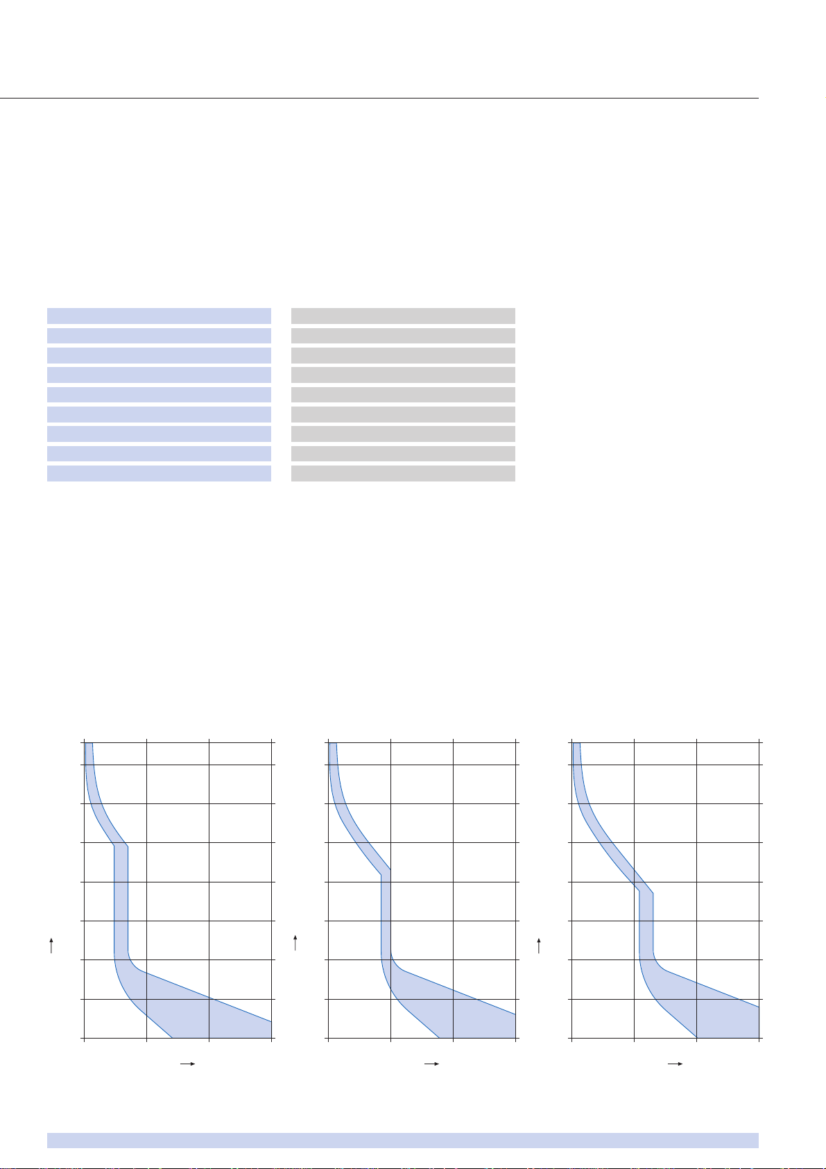
Tripping characteristic F
Auslösekennlinie F
Tripping characteristic G
Auslösekennlinie G
Tripping characteristic H
Auslösekennlinie H
Ambient Correction factor
temperature [°C] AC version DC version
–20 0,78 0,80
–5 0,82 0,87
0 0,83 0,90
+10 0,87 0,95
+23 0,91 1,00
+30 0,95 1,05
+40 1,00 1,10
+50 1,05 1,20
+60 1,11 1,30
Effect of ambient
temperature
AC-breakers are calibrated for an ambient
temperature of +40°C, DC-breakers for
+23°C. To determine the rated current for
a lower or higher ambient temperature, use
a correction factor from the table below:
Multiple of rated current (x In)
Nennstrom-Vielfaches (x In)
1 10 100 1000 x I
n
0,1ms
1ms
10ms
0,1s
1s
10s
100s
1000s
1hr
Tripping time / Auslösezeit
Multiple of rated current (x In)
Nennstrom-Vielfaches (x In)
1 10 100 1000 x I
n
0,1ms
1ms
10ms
0,1s
1s
10s
100s
1000s
1hr
Tripping time / Auslösezeit
Multiple of rated current (x In)
Nennstrom-Vielfaches (x In)
1 10 100 1000 x I
n
0,1ms
1ms
10ms
0,1s
1s
10s
100s
1000s
1hr
Tripping time / Auslösezeit
MANUAL MOTOR CONTROLLER AND SUPPLEMENTARY PROTECTOR
MOTOR- UND GERÄTESCHUTZSCHALTER AS168X
www.schurter.com
125
MANUAL MOTOR CONTROLLER AND SUPPLEMENTARY PROTECTOR
MOTOR- UND GERÄTESCHUTZSCHALTER AS168X
Technical data / Technische Daten
Pole / Pole:
Rated voltage U
e
AC versions / AC Versionen F; G; H AC 480/277 V; DC 65 V
Nennspannung U
e
DC versions / DC Versionen DF; DG; DH DC 180 V 1 pole / 1polig
DC 360 V 2 – 3 pole / 2 – 3polig
Note: The connection polarity must be strictly
observed. An application with a DC Type AS168X
in an AC network is not allowed.
Hinweis: Die Anschlusspolarität muss unbedingt
beachtet werden. Eine Anwendung von
DC Versionen in AC Netzen ist nicht zulässig.
Rated current I
n
See approvals, page 126 AC/DC 0,5 – 52 A
Nennstrom I
n
Siehe Approbationen Seite 126 AC/DC 0,5 – 52 A
Endurance Number of cycles at I
n
6000
Lebensdauer Anzahl Schaltspiele bei I
n
6000
Type of tripping • Thermal magnetic / thermisch-magnetisch TM
Auslöseart • Positively trip-free / positive Freiauslösung
Type of actuation / Betätigungsart Manual ON/OFF / Manuell EIN/AUS S-type / S-Typ
Permissible wire cross section 1,5 – 25 mm2/AWG #16...4
Zulässiger Leiterquerschnitt 1,5 – 25 mm2/AWG #16...4
Switched neutral / Schaltbarer, neutraler Pol:
Rated voltage Ue/ Nennspannung U
e
AC 277 V
Rated current In / Nennstrom I
n
AC/DC 65 A
Function The switched neutral closes with
manual closure of the poles and opens
automatically with thermal magnetic
tripping of the poles.
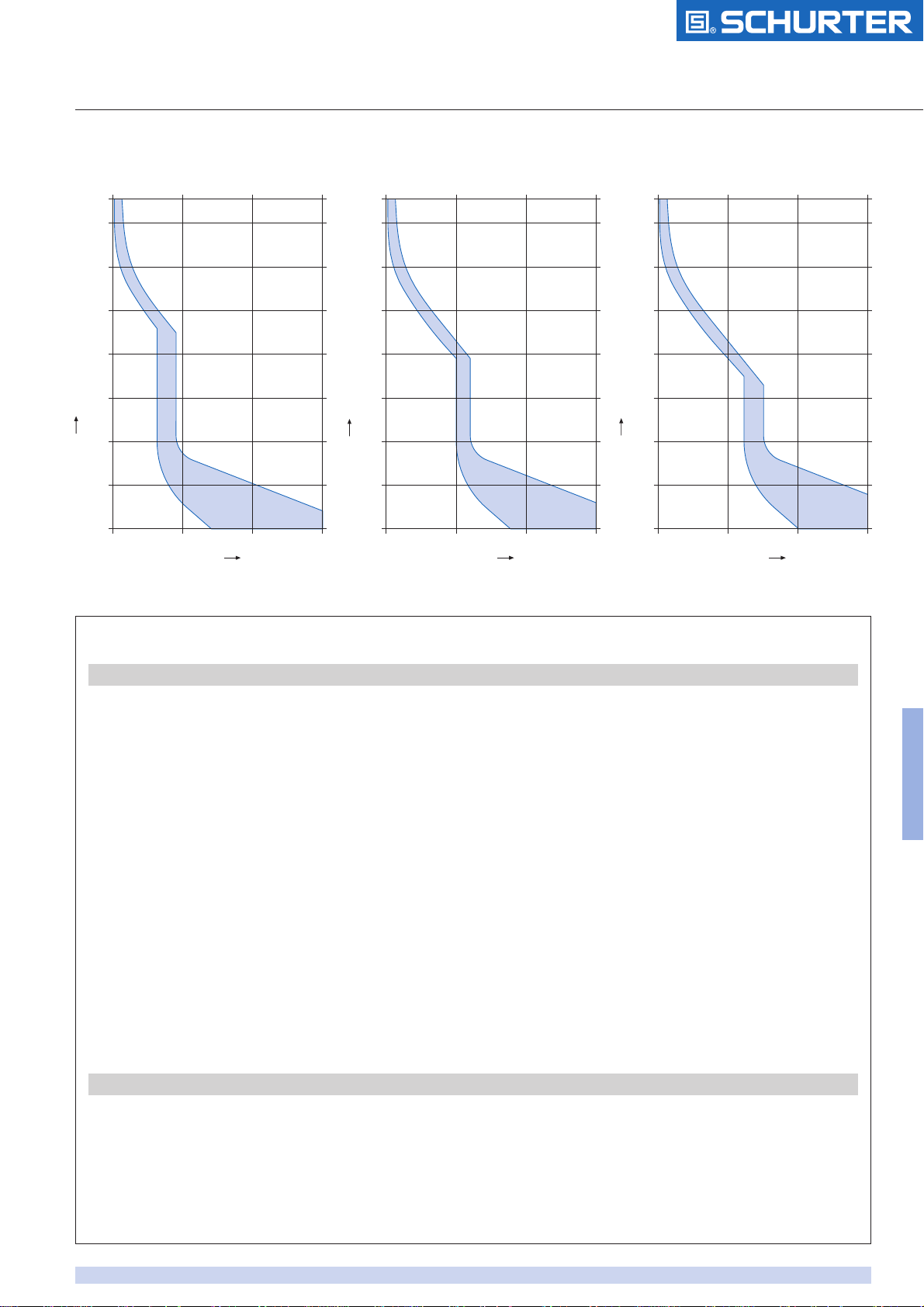
Tripping characteristic DF
Auslösekennlinie DF
Tripping characteristic DG
Auslösekennlinie DG
Tripping characteristic DH
Auslösekennlinie DH
Multiple of rated current (x In)
Nennstrom-Vielfaches (x In)
1 10 100 1000 x I
n
0,1ms
1ms
10ms
0,1s
1s
10s
100s
1000s
1hr
Tripping time / Auslösezeit
Multiple of rated current (x In)
Nennstrom-Vielfaches (x In)
1 10 100 1000 x I
n
0,1ms
1ms
10ms
0,1s
1s
10s
100s
1000s
1hr
Tripping time / Auslösezeit
Multiple of rated current (x In)
Nennstrom-Vielfaches (x In)
1 10 100 1000 x I
n
0,1ms
1ms
10ms
0,1s
1s
10s
100s
1000s
1hr
Tripping time / Auslösezeit

www.schurter.com
126
Technical data (continued) / Technische Daten (Fortsetzung)
Funktion Der Neutralleitertrenner schliesst bei
manueller Einschaltung der Pole und
öffnet automatisch bei thermischmagnetischer Auslösung der Pole.
Add-on modules / Zusatzmodule:
Rated voltage Ue/ Nennspannung U
e
Rated current In/ Nennstrom I
n
Auxiliary contact H1 & H2 and
Signal contact S1 & S2 AC 277 V 6 A
Hilfskontakt H1 & H2 und DC 125 V 1 A
Signalkontakt S1 & S2 DC 50 V 6 A
Functional auxiliary contact module Type H1 (assumes the same contact position) Actuation of the contact is determined
Type H2 (assumes the opposite position) by the condition of the handle position
of the adjacent poles.
Funktion Hilfskontakt Typ H1 (gleichschaltend) Hilfskontakte schalten bei thermisch-
Typ H2 (gegenschaltend) magnetischer Auslösung sowie
Handbetätigung synchron mit den
geschützten Polen.
Functional signal contact Type S1 (assumes the same contact position) The signal contact operates due to a
Type S2 (assumes the opposite position) thermal magnetic tripping and must
be reset by hand.
Funktion Signalkontakt Typ S1 (gleichschaltend) Signalkontakte schalten nur bei
Typ S2 (gegenschaltend) thermisch-magnetischer Auslösung
und sind von Hand zurückzustellen.
Relay trip module Type Voltage range AC/DC Impedance at 50 Hz
Fremdauslösung Typ Arbeitsbereich AC/DC Impedanz bei 50 Hz
A1 5 – 12 V 1.1 Ω
A2 10 – 24 V 4.7 Ω
A3 20 – 48 V 16 Ω
A4 40 – 110 V 63 Ω
A5 90 – 240 V 395 Ω
Function of relay trip module When voltage is applied across the
terminals, remote tripping takes place
by a self interrupting magnetic system.
Trip delay time 8 - 16 ms.
Funktion Fremdauslösung Beim Anlegen der Klemmenspannung
erfolgt die Auslösung durch ein
selbstunterbrechendes Magnetsystem.
Ausschaltverzögerung 8 – 16 ms.
General data / Allgemeine Daten:
Dielectric strength AC 2000 V
Spannungsfestigkeit AC 2000 V
Vibration resistance IEC 60068-2-6, Test Fc 0,75 mm amplitude, 10 – 57 Hz
Schwingungsfestigkeit 0,75 mm Amplitude, 10 – 57 Hz
Shock resistance / Stossfestigkeit IEC 60068-2-27, Test Ea 25 g / 10 ms Halfsinus
Protection against electric shock Finger safe per IEC 529 IP20
Berührungsschutz Fingerschutz nach IEC 529 IP20
Permissible ambient temperature -20°C to +60°C
Zul. Umgebungstemperatur -20°C bis +60°C
Weight / Gewichte 1 pole / 1-Pol ca. 130 g
Switched neutral / Schaltbarer neutraler Pol ca. 130 g
Auxiliary contact / Hilfskontakt ca. 100 g
Signal contact / Signalkontakt ca. 100 g
Relay trip module / Fremdauslösung ca. 120 g
MANUAL MOTOR CONTROLLER AND SUPPLEMENTARY PROTECTOR
MOTOR- UND GERÄTESCHUTZSCHALTER AS168X

MANUAL MOTOR CONTROLLER AND SUPPLEMENTARY PROTECTOR
MOTOR- UND GERÄTESCHUTZSCHALTER AS168X
Approvals / Approbationen
www.schurter.com
127
AC versions / AC-Versionen
DC versions / DC-Versionen
* VDE approval pending / VDE Zulassung pendent
** Rated currents 32–52 A available approx. March 2003 / Nennwerte 32–52 A ca. ab März 2003 lieferbar
EVD
EVD
VDE UL UL
Poles Characteristic/
Nennstrom [A]
1 F / G / H
45 - 52
F / G
0.5 - 25
H
0.5 - 40
F / G
27 - 40
2 F / G / H
45 - 52
F / G
0.5 - 25
H
0.5 - 40
F / G
27 - 40
3 F / G / H
45 - 52
F / G
0.5 - 25
H
0.5 - 40
F / G
27 - 40
4 F / G / H
0.5 - 52
EN 60934 * UL 1077
CSA 22.2 235
Volt AC Volt
DC
Icn [A] Volt AC Volt DC Icn [A] Volt AC Icn [A]
420/240 65 4500 277 65 5000 277 5000
420/240 65 4500 277
240 65
5000
10000
420/240 65 4500 277 65 5000 277 5000
420/240 65 4500 277
240 65
5000
10000
420 65 4500 480 65 5000 480 5000
420 65 4500 480 65 10000 480 5000
420 65 4500 480 65 5000 480 5000
420 65 4500 480 65 10000 480 5000
420 65 4500 480Y/277 65 5000 480 5000
420 65 4500 480Y/277 65 10000 480 5000
420 65 4500 480Y/277 65 5000 480 5000
420 65 4500 480Y/277 65 10000 480 5000
420/240 65 4500 480Y/277 65 5000 480Y/277 5000
UL 508 **
CSA 22.2 14
277 5000
277 5000
VDE * UL
EN 60934 UL 1077
CSA 22.2 235
Poles Characteristic/
Nennstrom [A]
1 DF / DG
Volt DC Icn [A] Volt DC Icn [A]
120 4500 180 2000
0.5 - 50
DH
120 4500 180 2000
6 - 50
2 DF / DG
240 4500 360 2000
0.5 - 50
DH
240 4500 360 2000
6 - 50
3 DF / DG
360 4500 360 10000
0.5 - 40
DF / DG
360 4500 360 5000
45 - 50
DH
360 4500 360 5000
6 - 50
4 DF / DG
360 4500 360 10000
0.5 - 40
DF / DG
360 4500 360 5000
45 - 50
DH
360 4500 360 5000
6 - 50

www.schurter.com
128
MANUAL MOTOR CONTROLLER AND SUPPLEMENTARY PROTECTOR
MOTOR- UND GERÄTESCHUTZSCHALTER AS168X
Conversion table Ampere rating – Horsepower rating / Umrechnungstabelle Ampère – Horsepower
HORSEPOWER
(FLA & LRC RATINGS APPLY WHERE NO HP RATING IS GIVEN)
NOMINAL CIRCUIT VOLTAGE, Vac
AS168X-CB MOTOR NAMEPLATE
110-
120
200 208
220-
240
265 277
380-
415
440-
480
Rated Current
(See Note #1)
FLA
Rating
Starting/
LRC Rating
1
pole
2 pole
0.5A 0.5A 3°
1A 1A 6° 1/10
1.5A 1.5A 9° 1/10 1/10 1/10 1/6
2A 2A 12A 1/8 1/6 1/6 1/4
3A 3A 18A 1/10 1/6 1/6 1/4 1/4 1/3 1/3 1/2
4A 4A 24A 1/8 1/4 1/3 1/3 1/3 1/3 1/2 1
5A 5A 30A 1/6 1/3 1/3 1/2 1/2 1/2 3/4 1 1/2
6A 6A 36A 1/4 1/2 1/2 1/2 3/4 3/4 1 2
7A 7A 42A 1/4 1/2 1/2 3/4 1 1 1 1/2 2
8A 8A 48A 1/3 3/4 3/4 1 1 1 2 2
9A 9A 54A 1/3 3/4 1 1 1 _ 1 1/2 2 3
10A 10A 60A 1/2 1 1 1 1/2 1 1/2 2 2 3
12A 12A 72A 1/2 1 1/2 1 1/2 2 2 2 3 3
13A 13A 78A 1/2 1 1/2 1 1/2 2 2 2 3 3
15A 15A 90A 3/4 2 2 2 3 3 3 5
16A 16A 96A 1 2 2 2 3 3 3 5
18A 18A 108A 1 2 2 3 3 3 5 5
20A 20A 120A 1 1/2 3 3 3 3 3 5 5
23A 23A 138A 1 1/2 3 3 3 3 3 5 7 1/2
25A 25A 150A 2 3 3 3 5 5 5 7 1/2
27A 27A 162A 2 3 3 3 5 5 7 1/2 10
30A 30A 180A 2 3 3 5 5 5 7 1/2 10
HORSEPOWER
(FLA & LRC RATINGS APPLY WHERE NO HP RATING IS GIVEN)
AS168X-CB
MOTOR
NAMEPLATE
NOMINAL CIRCUIT VOLTAGE, VAC
110-120 200 208 220-240 380-415 440-480
Rated Current
(See Note #1)
FLA
Rating
Starting/
LRC Rating
3 pole
0.5A 0.5A
1A 1A
1.5A 1.5A 10A 1/2 1/2
2A 2A 12.5A 3/4 3/4
3A 3A 20A 1/2 1/2 1/2 1 1 1/2
4A 4A 25A 3/4 3/4 3/4 1 1/2 2
5A 5A 32A 1/2 1 1 1 2 3
6A 6A 32A 1/2 1 1 1 1/2 2 3
7A 7A 32A 3/4 1 1/2 1 1/2 2 3 3
8A 8A 46A 3/4 2 2 2 3 5
9A 9A 46A 1 2 2 2 3 5
10A 10A 46A 1 2 2 3 5 5
12A 12A 63.5A 1 1/2 3 3 3 5 7 1/2
13A 13A 63.5A 1 1/2 3 3 3 5 7 1/2
15A 15A 81A 2 3 3 3 7 1/2 10
16A 16A 81A 2 3 3 5 7 1/2 10
18A 18A 81A 2 5 5 5 10 10
20A 20A 81A 3 5 5 5 10 10
23A 23A 116A 3 5 5 7 1/2 10 15
25A 25A 116A 3 5 7 1/2 7 1/2 10 15
27A 27A 145A 3 7 1/2 7 1/2 7 1/2 15 20
30A 30A 145A 3 7 1/2 7 1/2 10 15 20
HP-Rating: 1 phase (1 pole & 2 pole):
Note #1: For AC motor circuit nameplate FLA loads, AC general-use loads, AC resistance loads
Voltage Rating: One pole: AC 277 V, 1 phase
Two pole: AC 480Y/277 V, 1 phase
Three pole: AC 480Y/277 V, 3 phase
HP-Rating: 3 phase (3 pole):

www.schurter.com
129
Order code / Bestellcode
Basic type / Grundtyp
Thermal magnetic high performance circuit breaker
Thermisch-magnetischer Hochleistungs-Geräteschutzschalter
Number of poles / Polzahl
1
2
3
4
Tripping characteristics / Auslösekennlinien
Thermal Magnetic Deliverable currents
Thermisch Magnetisch Lieferbare Nennströme
F 1.0–1.25 xI
n
3 – 5 xI
n
0,5 – 52 A
G 1.0–1.25 xI
n
6 – 10 xI
n
0,5 – 52 A
H 1.0 –1.25 xI
n
12 – 20 xI
n
0,5 – 52 A
DF 1.05–1.35 xI
n
4,5 – 8 xI
n
0,5 – 50 A
DG 1.05 –1.35 xI
n
9 – 16 xI
n
0,5 – 50 A
DH 1.05 –1.35 xI
n
18 – 32 xI
n
6,0 – 50 A
Rated current / Nennstrom
Switched neutral pole / Schaltbarer neutraler Pol
N
Auxiliary contact / Hilfskontakt
H1 Assumes the same contact position as the protected poles
Gleiche Kontaktposition wie die geschützten Pole (gleichschaltend)
H2 Assumes the opposite contact position as the protected poles
Entgegengesetzte Kontaktposition wie die geschützten Pole (gegenschaltend)
Signal contact / Signalkontakt
S1 Assumes the same contact position as the protected poles
Gleiche Kontaktposition wie die geschützten Pole (gleichschaltend)
S2 Assumes the opposite contact position as the protected poles
Entgegengesetzte Kontaktposition wie die geschützten Pole (gegenschaltend)
Relay trip module / Fremdauslösung
A1 AC/DC 5 – 12 V
A2 AC/DC 10 – 24 V
A3 AC/DC 20 – 48 V
A4 AC/DC 40 – 110 V
A5 AC/DC 90 – 240 V
Accessories / Zubehör
Must be ordered separately / muss separat bestellt werden
2 DG
200
N
AS168X – CB
S2
AS168X – ACB
Code In(A)
060 6.0
070 7.0
080 8.0
090 9.0
100 10.0
120 12.0
150 15.0
Code In(A)
005 0.5
010 1.0
015 1.5
020 2.0
030 3.0
040 4.0
050 5.0
Code In(A)
160 16.0
180 18.0
200 20.0
230 23.0
250 25.0
270 27.0
300 30.0
Code In(A)
320 32.0
350 35.0
400 40.0
450 45.0
500 50.0
520 52.0*
Maximum
combination
Maximale
Kombinationen
1 Add-on module +
1 Zusatzmodul +
N
N
4 poles +
4 Pole +
A1 ... A5/ S1, S2/ H1, H2
A1 ... A5/ S1, S2/ H1, H2
A1 ... A5/ S1, S2/ H1, H2
2 Add-on modules +
2 Zusatzmodule +
N
N
3 poles +
3 Pole +
MANUAL MOTOR CONTROLLER AND SUPPLEMENTARY PROTECTOR
MOTOR- UND GERÄTESCHUTZSCHALTER AS168X
* AC version only /
Nur AC-Version

www.schurter.com
130
MANUAL MOTOR CONTROLLER AND SUPPLEMENTARY PROTECTOR
MOTOR- UND GERÄTESCHUTZSCHALTER AS168X
DIN rail mounting / Hutschiene DIN-Befestigung
AS168X-CB1… …N
45
35
90
1.9
44.4
61.6
68.4
5.1
26.6
17.5
+0.5
– 0.0
26.6
17.5
+0.5
– 0.0
35 mm DIN rail EN 50022
35 mm Hutschiene DIN-EN 50022
Wire crosssection Max. torque
Drahtquerschnitt Max. Drehmoment
1.5…10 mm
2
2.5 Nm
16 …25 mm
2
3.1 Nm
AWG #16...8 22 Ib–in
AWG #6...4 28 Ib–in
Max. torque
Max. zulässiges Anzugsdrehmoment
AS168X-ACBH.
AS168X-ACBS.
AS168X-ACBA.
90
17.5
+0.5
– 0.0
90
17.5
+0.5
– 0.0
90
17.5
+0.5
– 0.0

Accessories / Zubehör
AS168X-ACBLOA
Lockout attachment / Abschliessverriegelung
Schematic diagrams / Schaltbilder
AS168X-CB1…
AS168X-ACBH2
AS168X-CB1…
AS168X-ACBH1
AS168X-CB1…N
AS168X-CB1…
AS168X-CB1…
AS168X-ACBS1
AS168X-CB1…
AS168X-ACBS2
AS168X-CB1…
AS168X-ACBA.
MANUAL MOTOR CONTROLLER AND SUPPLEMENTARY PROTECTOR
MOTOR- UND GERÄTESCHUTZSCHALTER AS168X
www.schurter.com
131
 Loading...