

Page 1
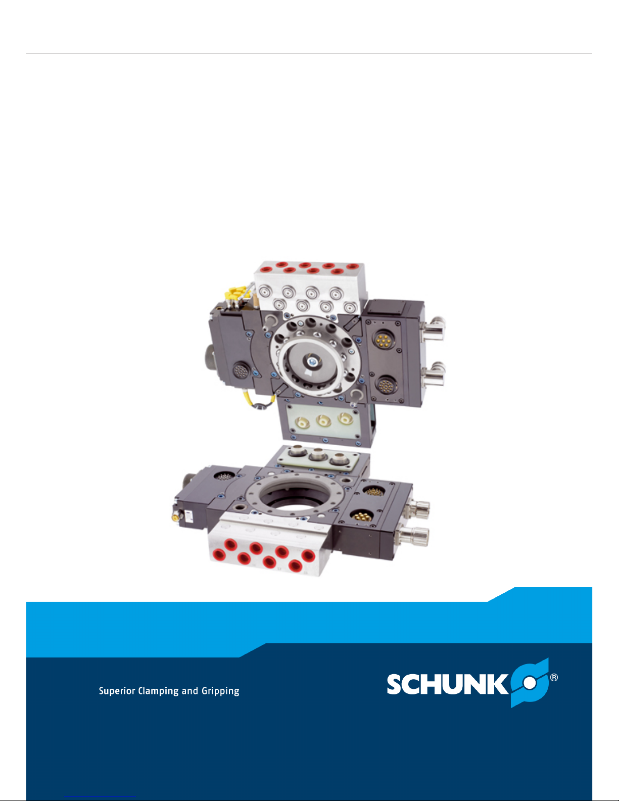
Original manual
Assembly and operating manual
SWS-L
Heavy Load Change System
Page 2

Imprint
2
02.00 | SWS-L | Assembly and operating manual | en | 0389037
Imprint
Copyright:
This manual is protected by copyright. The author is SCHUNK GmbH & Co. KG. All rights reserved. Any reproduction, processing, distribution (making available to third parties),
translation or other usage - even excerpts - of the manual is especially prohibited and requires our written approval.
Technical changes:
We reserve the right to make alterations for the purpose of technical improvement.
Document number: 0389037
Version: 02.00|12/11/2018|en
© SCHUNK GmbH & Co. KG
All rights reserved.
Dear Customer,
thank you for trusting our products and our family-owned company, the leading techno-
logy supplier of robots and production machines.
Our team is always available to answer any questions on this product and other solutions.
Ask us questions and challenge us. We will find a solution!
Best regards,
Your SCHUNK team
SCHUNK GmbH & Co. KG
Spann- und Greiftechnik
Bahnhofstr. 106 – 134
D-74348 Lauffen/Neckar
Tel. +49-7133-103-0
Fax +49-7133-103-2399
[email protected]
schunk.com
Page 3

Table of contents
02.00 | SWS-L | Assembly and operating manual | en | 0389037
3
Table of contents
1 General.................................................................................................................... 5
1.1 About this manual ................................................................................................5
1.1.1 Presentation of Warning Labels ...............................................................5
1.1.2 Applicable documents ..............................................................................6
1.2 Warranty .............................................................................................................. 6
1.3 Accessories ........................................................................................................... 6
2 Basic safety notes ................................................................................................... 7
2.1 Intended use......................................................................................................... 7
2.2 Not intended use.................................................................................................. 7
2.3 Ambient conditions and operating conditions ..................................................... 7
2.4 Personnel qualification......................................................................................... 8
2.5 Personal protective equipment............................................................................ 8
2.6 Notes on particular risks....................................................................................... 9
3 Technical Data ........................................................................................................11
4 Product description.................................................................................................13
4.1 Quick-change head (SWK-L) ............................................................................... 13
4.2 Quick Change Adapter (SWA-L) ..........................................................................16
4.3 Optional Modules............................................................................................... 18
5 Installation .............................................................................................................19
5.1 SWK-L ................................................................................................................. 21
5.2 SWA-L .................................................................................................................22
5.3 Tool Stand Design ............................................................................................... 23
6 Operation ...............................................................................................................25
6.1 Coupling Sequence ............................................................................................. 25
6.2 Fail-Safe Operation............................................................................................. 27
6.3 Uncoupling ......................................................................................................... 27
6.4 Integrated Sensors (SWS-L-1210) ....................................................................... 29
7 Troubleshooting .....................................................................................................31
8 Maintenance and Care............................................................................................35
8.1 Preventive Maintenance .................................................................................... 35
8.2 Cleaning, Lubrication, Adjustment and Replacement ........................................37
8.2.1 Cleaning and Lubrication of the Locking Mechanism ............................37
8.2.2 Lock and Unlock Sensor Assembly Replacement....................................39
8.2.3 Lock/Unlock Sensor Adjustment and Replacement (Units using individual
sensors) .................................................................................................. 44
8.2.4 RTL Sensor Replacement ........................................................................46
8.2.5 Alignment Pin Replacement ...................................................................49
8.3 Recommended Spare Parts ................................................................................51
Page 4

Table of contents
4
02.00 | SWS-L | Assembly and operating manual | en | 0389037
8.3.1 SWS-L-210...............................................................................................51
8.3.2 SWS-L-310...............................................................................................51
8.3.3 SWS-L-510...............................................................................................51
8.3.4 SWS-L-1210.............................................................................................51
8.4 Assembly drawings ............................................................................................. 52
8.4.1 SWS-L-210...............................................................................................52
8.4.2 SWS-L-310...............................................................................................54
8.4.3 SWS-L-510...............................................................................................56
8.4.4 SWS-L-1210.............................................................................................58
9 Translation of original declaration of incorporation ................................................60
9.1 Annex to Declaration of Incorporation............................................................... 61
Page 5
General
02.00 | SWS-L | Assembly and operating manual | en | 0389037
5
1 General
1.1 About this manual
This manual contains important information for a safe and appropriate use of the product.
This manual is an integral part of the product and must be kept accessible for the personnel at all times.
Before starting work, the personnel must have read and understood this operating manual. Prerequisite for safe working is the
observance of all safety instructions in this manual.
Illustrations in this manual are provided for basic understanding
and may differ from the actual product design.
In addition to these instructions, the documents listed under Ap-
plicable documents [}6] are applicable.
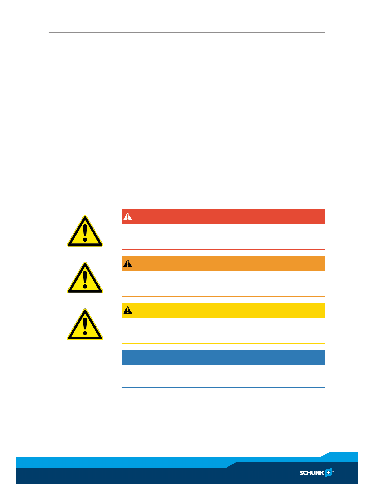
1.1.1 Presentation of Warning Labels
To make risks clear, the following signal words and symbols are
used for safety notes.
DANGER
Danger for persons!
Non-observance will inevitably cause irreversible injury or death.
WARNING
Dangers for persons!
Non-observance can lead to irreversible injury and even death.
CAUTION
Dangers for persons!
Non-observance can cause minor injuries.
NOTICE
Material damage!
Information about avoiding material damage.
Page 6

General
6
02.00 | SWS-L | Assembly and operating manual | en | 0389037
1.1.2 Applicable documents
• General terms of business*
• Catalog data sheet of the purchased product *
• Assembly and operating manuals of the accessories *
The documents marked with an asterisk (*) can be downloaded on
our homepage schunk.com
1.2 Warranty
If the product is used as intended, the warranty is valid for 24
months from the ex-works delivery date under the following conditions:
• Observe the specified maintenance and lubrication intervals
• Observe the ambient conditions and operating conditions
Parts touching the workpiece and wear parts are not included in
the warranty.
1.3 Accessories
A wide range of accessories are available for this product
For information regarding which accessory articles can be used
with the corresponding product variants, see catalog data sheet.
Page 7

Basic safety notes
02.00 | SWS-L | Assembly and operating manual | en | 0389037
7
2 Basic safety notes
2.1 Intended use
The product (quick-change system SWS-L, consisting of quickchange head SWK-L and quick-change-adapter SWA-L) was designed for quickly changing parts and automation components at a
robot in context of the technical data.
• The product is intended for installation in a machine/system or
for mounting to a robot. The applicable guidelines must be observed and complied with.
• When implementing and operating components in safety-related parts of the control systems, the basic safety principles in
accordance with DIN EN ISO 13849-2 apply. The proven safety
principles in accordance with DIN EN ISO 13849-2 also apply to
categories 1, 2, 3 and 4.
• Make sure that the product is only used within its defined application parameters.
• The product is intended for industrial use.
2.2 Not intended use
It is not intended use if the product is used, for example, as a
pressing tool, stamping tool, lifting gear, guide for tools, cutting
tool, clamping device or a drilling tool.
• Any utilization that exceeds or differs from the appropriate use
is regarded as misuse.
2.3 Ambient conditions and operating conditions
Required ambient conditions and operating conditions
Incorrect ambient and operating conditions can make the product
unsafe, leading to the risk of serious injuries, considerable material
damage and/or a significant reduction to the product's life span.
• Make sure that the product is used only in the context of its
defined application parameters, Technical Data [}11].
• Make sure that the product is a sufficient size for the application.
• Make sure that the environment is free from splash water and
vapors as well as from abrasion or processing dust. Exceptions
are products that are designed especially for contaminated environments.
Page 8

Basic safety notes
8
02.00 | SWS-L | Assembly and operating manual | en | 0389037
2.4 Personnel qualification
Inadequate qualifications of the personnel
If the personnel working with the product is not sufficiently qualified, the result may be serious injuries and significant property
damage.
• All work may only be performed by qualified personnel.
• Before working with the product, the personnel must have read
and understood the complete assembly and operating manual.
• Observe the national safety regulations and rules and general
safety instructions.
The following personal qualifications are necessary for the various
activities related to the product:
Trained electrician
Due to their technical training, knowledge and experience, trained
electricians are able to work on electrical systems, recognize and
avoid possible dangers and know the relevant standards and regulations.
Qualified personnel
Due to its technical training, knowledge and experience, qualified
personnel is able to perform the delegated tasks, recognize and
avoid possible dangers and knows the relevant standards and regulations.
Instructed person
Instructed persons were instructed by the operator about the delegated tasks and possible dangers due to improper behaviour.
Service personnel of
the manufacturer
Due to its technical training, knowledge and experience, service
personnel of the manufacturer is able to perform the delegated
tasks and to recognize and avoid possible dangers.
2.5 Personal protective equipment
Use of personal protective equipment
Personal protective equipment serves to protect staff against
danger which may interfere with their health or safety at work.
• When working on and with the product, observe the occupational health and safety regulations and wear the required personal protective equipment.
• Observe the valid safety and accident prevention regulations.
• Wear protective gloves to guard against sharp edges and
corners or rough surfaces.
• Wear heat-resistant protective gloves when handling hot surfaces.
• Wear protective gloves and safety goggles when handling hazardous substances.
• Wear close-fitting protective clothing and also wear long hair in
a hairnet when dealing with moving components.
Page 9
Basic safety notes
02.00 | SWS-L | Assembly and operating manual | en | 0389037
9
2.6 Notes on particular risks
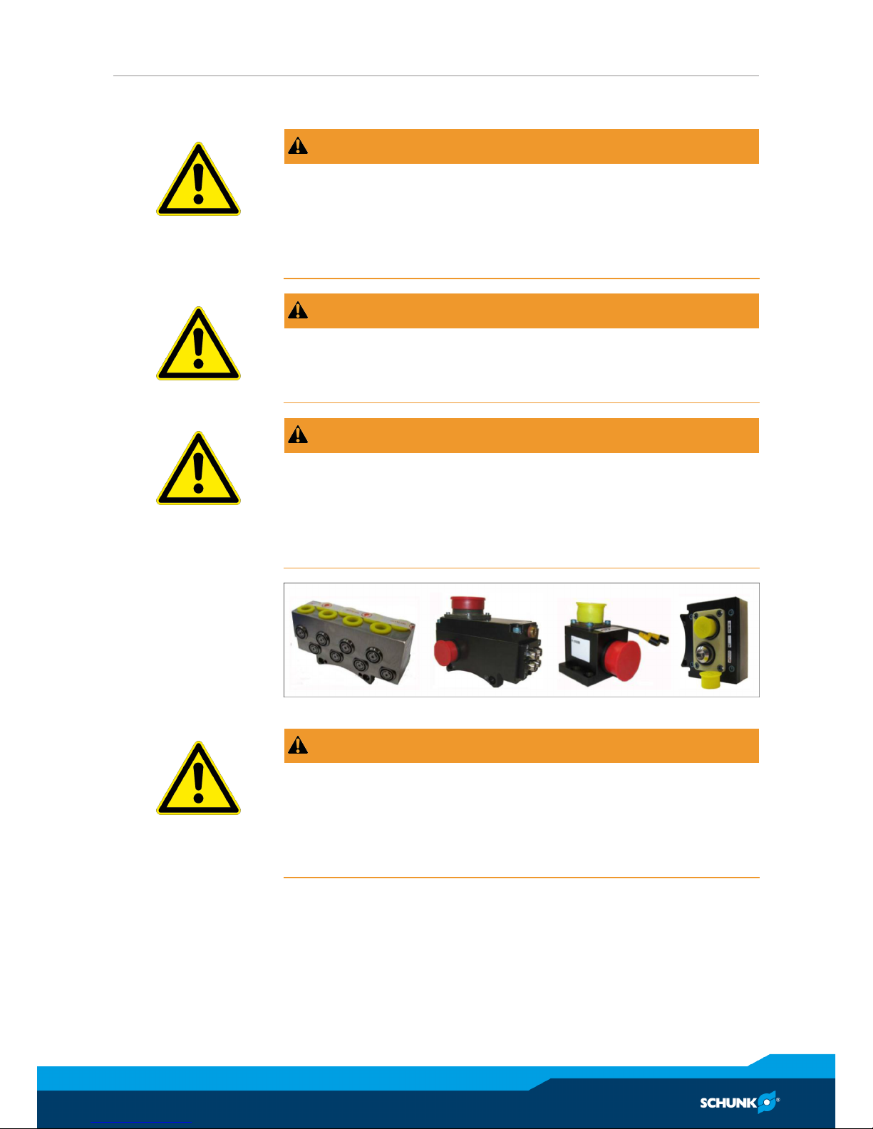
WARNING
Risk of injury from objects falling and being ejected!
Falling and ejected objects during operation can lead to serious
injury or death.
• Take appropriate protective measures to secure the danger
zone.
WARNING
Risk of injury due to unexpected movement of the machine/system!
• Switch off the energy supply.
WARNING
Remove all temporary protective materials (caps, plugs, tape,
etc.) on locking face of Tool Changer and modules prior to operation. Failure to do so will result in damage to Tool Changers,
modules, and end-of-arm tooling and could cause injury to personnel.
WARNING
Injury or equipment damage can occur with power or air on.
• Do not perform maintenance or repair on Tool Changer or
modules with power or air on.
• Turn off power and air before performing maintenance or re-
pair on Tool Changer or modules.
Page 10
Basic safety notes
10
02.00 | SWS-L | Assembly and operating manual | en | 0389037
WARNING
During operation, the area between the Quick-Chance-Head
SWK and Quick Change Adapter SWA must be kept clear.
Failure to keep area clear will result in damage to Tool Changer,
modules , or end-of-arm tooling and could cause injury to personnel.
WARNING
Using the Tool Changer in applications other than intended will
result in damage to Tool Changer, modules, or end-of-arm tooling and could cause injury to personnel.
• The Tool Changer is only to be used for intended applications
and applications approved by the manufacturer.
CAUTION
The SWK locking mechanism must not be actuated without being mounted to the robot interface plate.
Damage to the Cover Plate and O-ring may result.
• Always attach the SWK to the Robot interface plate prior to at-
tempting any operations.
Page 11
Technical Data
02.00 | SWS-L | Assembly and operating manual | en | 0389037
11
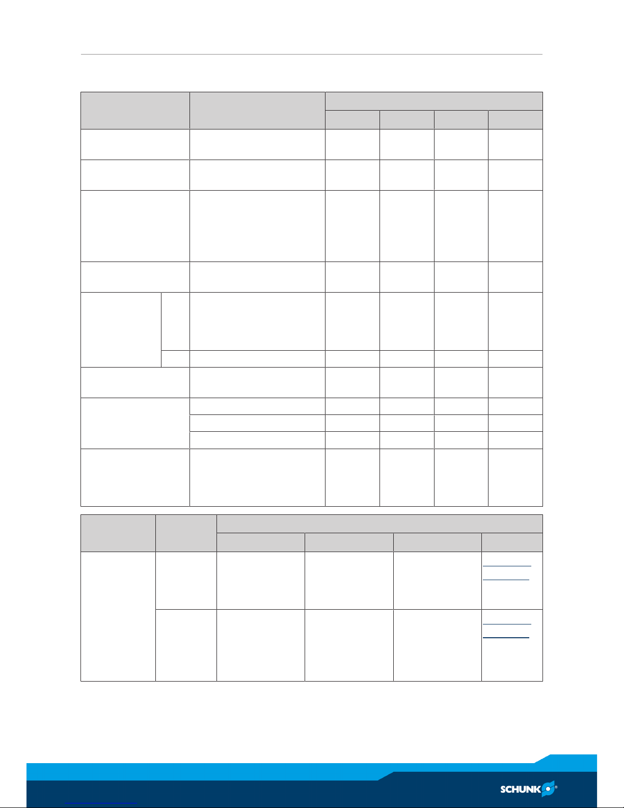
3 Technical Data
Designation Description SWS-L
210 310 510 1210
Suggested Payload
[kg]
The mass attached to the
Tool Changer.
300 510 700 1350
Working temperature
[°C]
5 – 60 5 – 60 5 – 60 5 – 60
Operating pressure
[bar]
Locking mechanism supply pressure operating
range. Supply to be clean,
dry, and filtered to 50 micron or better.
5 – 6.9 5 – 6.9 5 – 6.9 5 – 6.9
Coupling Force @ 5,5
bar [N]
Axial holding force. 31,000 38,000 62,000 93,000
Max. Moment
Load [Nm]
(X, Y) Maximum recommended
working load for optimum
performance of the Tool
Changer.
8,100 9,900 14,700 16,200
(Z) Torsion 6,900 9,600 10,500 16,200
Positional Repeatability [mm]
Repeatability tested at rated
load at one million cycles.
0.015
Weight [kg]
(coupled, no modules)
Total 8.2 20.4 28 28
SWK-L 5.4 12.7 19.3 18
SWK-A 2.7 7.7 8.7 10
Max. Recommen-
ded distance
between SWK-L and
SWA-L [mm]
No-Touch™ locking technology allows the SWK-L and
SWA-L to lock with separation when coupling.
2.5 2.5 2.5 1
Designation Description SWS-L
210 310 510 1210
Mounting/
Customer
Interface
SWK-L Meets
ISO 9409-1-A125
Meets
ISO 9409-1-A200
Also Supports
ABB ISO Pattern
Meets ISO 94091-200-6-M12
(Position 11)
Assembly
drawings
[}52]
SWA-L Meets ISO
9409-1-A125
Also supports (8)
Fasteners on 160
mm BC Pattern
Meets ISO 94091-A200
Also Supports
(6) Fasteners on
ABB ISO Pattern
ISO 94091-200-12-M16
(Position 12)
Assembly
drawings
[}52]
Page 12

Technical Data
12
02.00 | SWS-L | Assembly and operating manual | en | 0389037
Designation Description 210 - 510 1210
Sensor Information,
signal name
L/U (Lock/Unlock) Internal proximity
sensors (2) with cable
and connector for direct
wiring to the control/
signal module to indicate locking mechanism
position.
Internal proximity
sensors (6) with cable
and connector to indicate locking mechanism
position.
RTL
(Ready-To-Lock)
Flat Pack proximity
sensor with cable and
connector for direct wiring to control/signal
module to indicate SWKL and SWA-L mating surfaces within close proximity of each other.
Proximity sensors (3)
with cable and connector for direct wiring
to control/signal module
to indicate SWK-L and
SWA-L mating surfaces
within close proximity of
each other.
Page 13

Product description
02.00 | SWS-L | Assembly and operating manual | en | 0389037
13
4 Product description
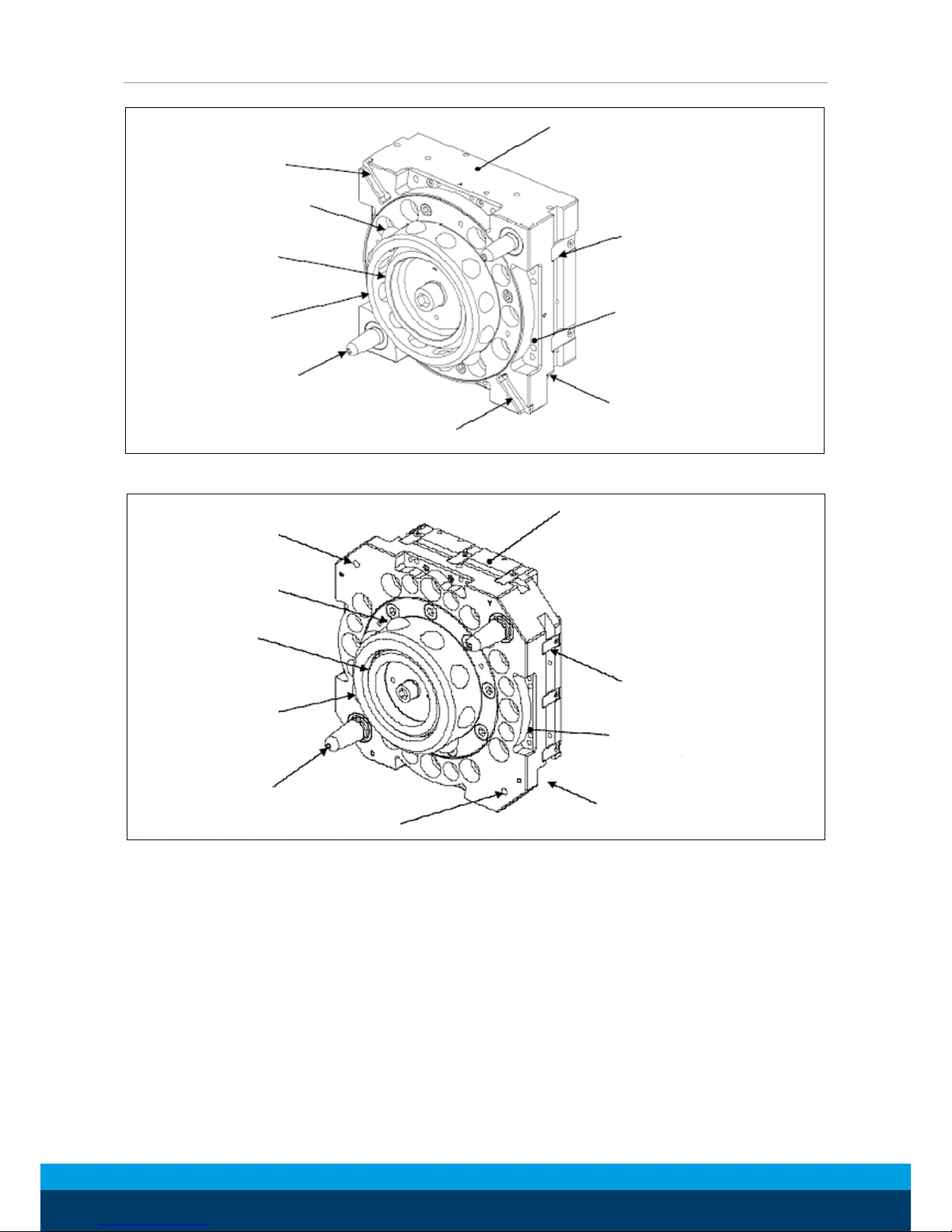
4.1 Quick-change head (SWK-L)
The Quick-change head (SWK-L) includes an anodized aluminum
body, a hardened stainless-steel locking mechanism, and hardened
steel alignment pins (see Figure).
The SWK-L plate has 4 (SWK-L-1210 Series: 6) flat sides for mounting of optional modules. Flat ‘A’ is dedicated for mounting of the
control/signal module along with SWK-L supply air that is provided
through an air or valve adapter. Flats ‘B’, ‘C’, and ‘D’ (SWS-L-1210
Series and ‘F’) are fully interchangeable and optional modules can
be arranged to suit the application or robot dress as required.
The locking mechanism consists of a cylindrical housing with holes
that retain hardened chrome-steel balls. Tapered pins located on
the SWK-L mate with holes in the SWA-L to ensure repeatable
alignment during the coupling process. An extreme pressure
grease is applied to the cam, male coupling, ball bearings and
alignment pins to enhance performance and maximize life of the
components.
SWK-L-210: A dual-sensor assembly is mounted into the body of
the SWK-L to verify the lock/unlock position of the piston and cam.
The sensors provide the lock and unlock (L/U) signals through the
control/signal module.
SWK-L-310 and 510: Proximity sensors are designed into the body
of the SWK-L to verify the lock/unlock position of the piston and
cam. The sensors provide the lock and unlock (L/U) signals through
the control/signal module.
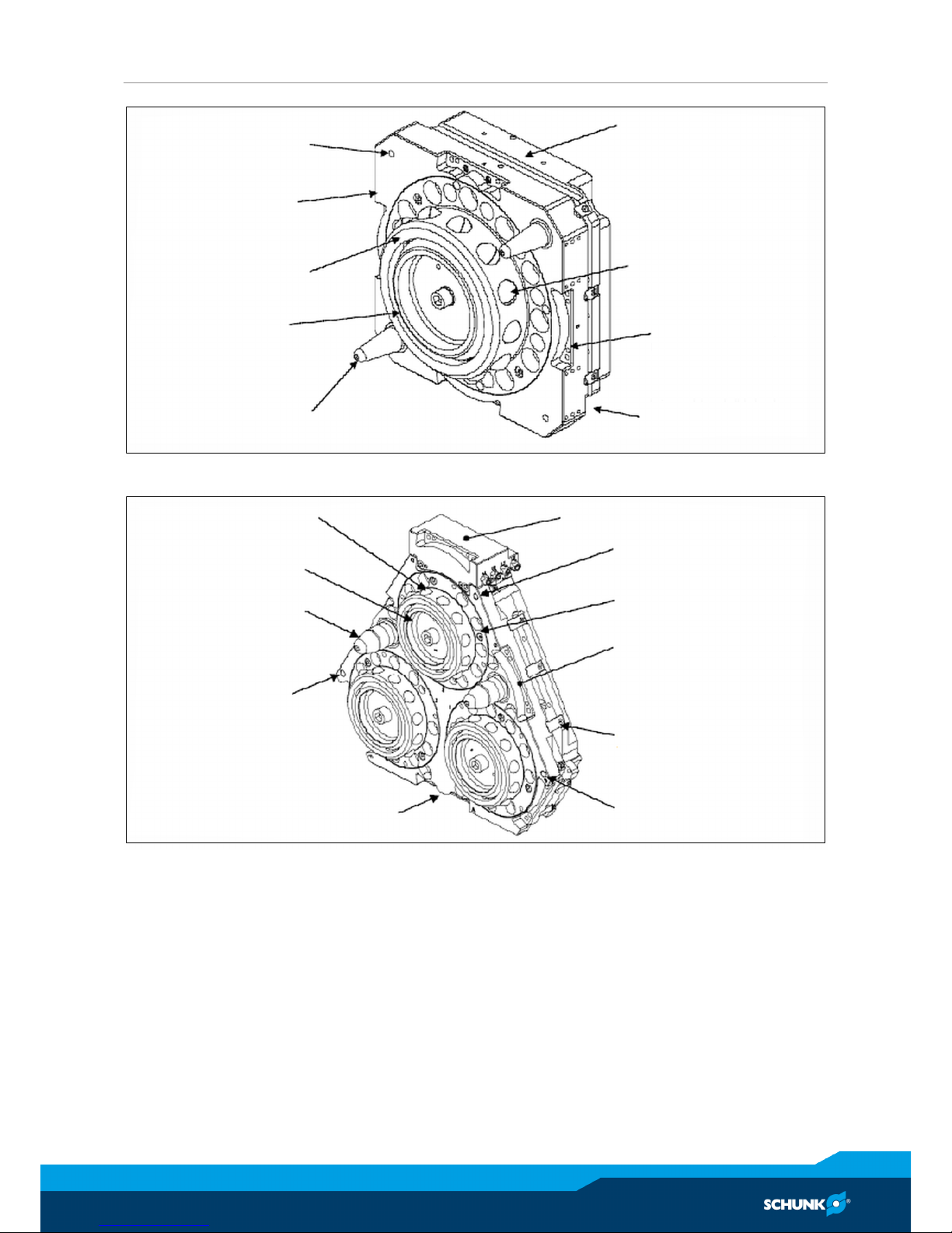
SWK-L-1210: The SWK-L is comprised of 3 locking mechanisms.
Each locking mechanism consists of a cam, male coupling, and
chrome-steel balls. Tapered pins located on the SWK-L mate with
holes in the SWA-L to ensure repeatable alignment during the
coupling process. Extreme pressure grease is applied to the cams,
male couplings, ball bearings, and pins to enhance performance
and maximize the life of the SWK-L.
Proximity sensors (6 total) are designed into the body of the SWK-L
to verify the locked/unlocked position of each locking mechanism.
Due to the multiple locking mechanism design, the proximity
sensors are grouped such that 3 sensors are for Lock and 3 are for
Unlock. The Lock/Unlock signal at each locking mechanism is
routed to the signal junction module. The junction module
provides the control/signal module with the Lock/Unlock state of
the SWK-L. See the cable routing illustrations in chapter "Installation" to understand the relationship between the sensors, junction
module and control module.)
Page 14
Product description
14
02.00 | SWS-L | Assembly and operating manual | en | 0389037
Prox Sensor
Location
(RTL Signal)
Ball Bearing (12x)
Cam
Male Coupling
Alignment Pin (2x)
Lock/UnlockAir Supplied Thru
Air/Valve Adapter Maunted to FlatA
Cable Retaining
Tabs
Common Ledge Feature
For Modul Mounting;
Flats B, C, and D
Internal Prox Sensors
(Lock/Unlock)
[Not Visible]
Prox Sensor
Location
(RTL Signal)
SWK-L 210
Prox Sensor
(RTL Signal)
Ball Bearing (9x)
Cam
Male Coupling
Alignment Pin (2x)
Lock/UnlockAir Supplied
Thru Air/Valve
Adapter Mounted to Flat A
Cable Retaining
Tabs
Common Ledge
Mounting Feature (3x)
Internal Prox Sensors
(Lock/Unlock)
[Not visible]
Prox Sensor
(RTL Signal)
SWK-L 310
Page 15
Product description
02.00 | SWS-L | Assembly and operating manual | en | 0389037
15
Prox Sensors (2x)
(RTL Signal)
Body
Male Coupling
Cam
Alignment Pins (2x)
Lock/Unlock air
supplied via Air/Valve
Adapter
mounted to Flat A
Ball Bearings (12x)
Common ledge
mounting feature (3x)
Internal Lock/Unlock
sensors
(Not visible)
SWK-L 510
Ball Bearings (36x)
Cam
Alignment Pin
Proximity Sensor
(RTL Signal)
Lock/Unlock Air Supplied through
Air/Valve Adapter Mounted to Flat A
Junction Modul
Proximity Sensor
(RTL Signal)
Male Coupling
Common Ledge Feature
For Module Mounting;
Flats A, B, C, D, E and F
Cable Retaining
Tabs
Proximity Sensor
(RTL Signal)
SWK-L 1210
Page 16
Product description
16
02.00 | SWS-L | Assembly and operating manual | en | 0389037
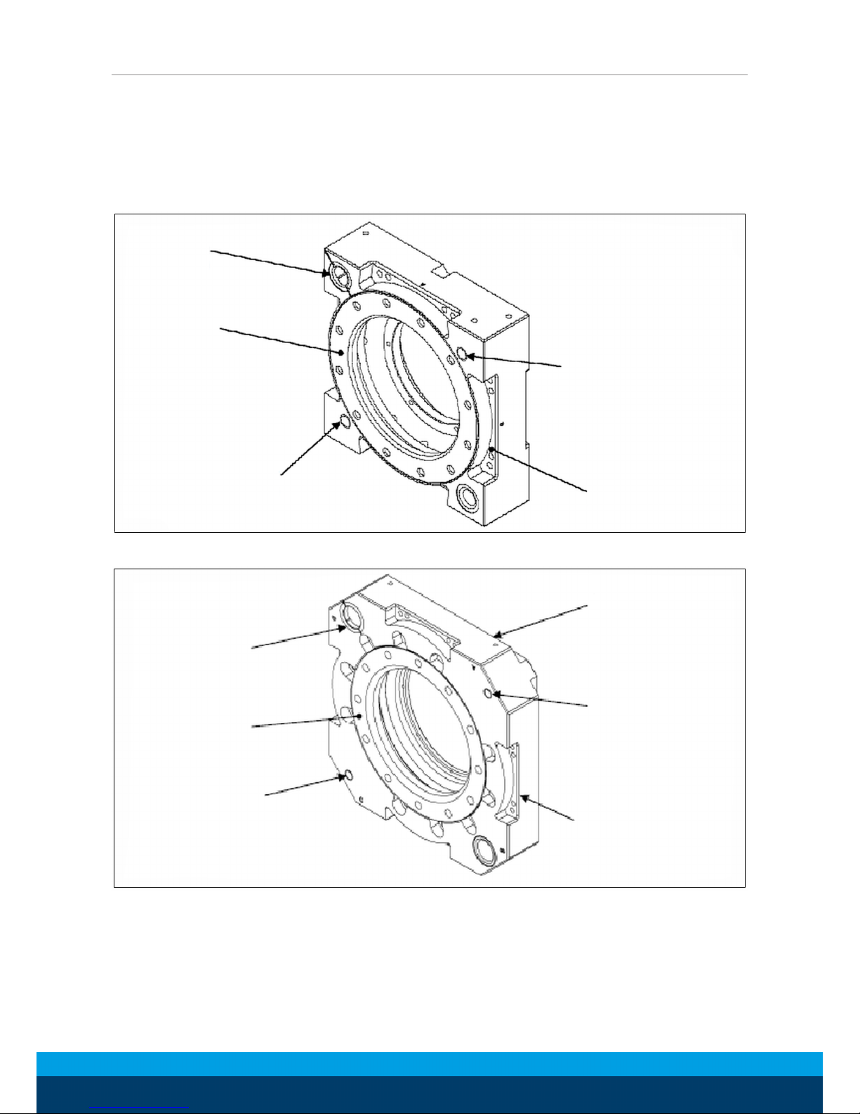
4.2 Quick Change Adapter (SWA-L)
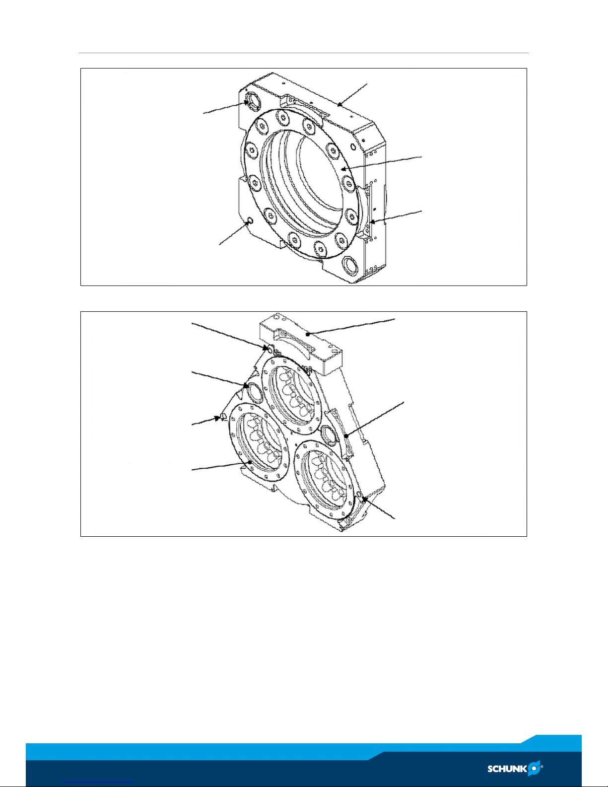
The Quick Change Adapter (SWA-L) includes an anodized aluminum body and a hardened stainless-steel bearing race (SWSL-1210: 3 hardened stainless-steel bearing races). The SWA-L has 4
(SWS-L-1210: 6) flat sides for mounting of optional modules.
Alignment Pin
Bushing (2x)
Bearing Race
Prox Sensor
Target (RTL)
Prox Sensor
Target (RTL)
Common Ledge Feature
for Module Mounting:
Flats A, B, C, and D
SWA-L 210
Alignment Pin
Bushing (2x)
Bearing Race
Prox Sensor Target
(RTL)
SWA-L (Body)
Prox Sensor or Target
(RTL)
Common Ledge
Mountong Feature (4x)
SWA-L-310
Page 17
Product description
02.00 | SWS-L | Assembly and operating manual | en | 0389037
17
Bushings for Alignment
Pin Location (2x)
RTL Sensor
Target (2x)
SWA-L (Body)
Bearing Race
Common Ledge
Mounting Feature (4x)
SWAS-L-510
Proximity Sensor
Target (RTL)
Alignment Pin Bushing
Proximity Sensor
Target (RTL)
Bearing Race
Junction Module
Adapter
Common Ledge Feature
For Module Mounting;
Flats A, B, C, D, E and F
Proximity Sensor
Target (RTL)
SWA-L-1210
Page 18

Product description
18
02.00 | SWS-L | Assembly and operating manual | en | 0389037
4.3 Optional Modules
There are 4 (SWS-1210: 6) flats available for mounting of the optional modules for support of various utility pass-through, such as
signal, fluid/air, and power.
For assistance in choosing the right modules for your particular application, visit our website to see what is available or contact an
SCHUNK Sales Representative directly.
In general, flat ‘A’ is reserved for an air/valve adapter module and
a control/signal module.
Modules for flats ‘B’, ‘Modules for flats ‘B’, ‘C’, or ‘D’ (SWS-1210:
or ’F’) are interchangeable to suit the application or the dress-out
required.
The optional modules are mounted to the SWK-L or SWA-L using a
common ledge mounting feature. Only 2 M6 SHCS fasteners need
to be unscrewed in order to remove the module from the SWK-L/
SWA-L. A secondary mounting support, called a “cleat”, is factoryinstalled to the SWK-L and SWA-L on each flat that is occupied
with a module. The cleats provide additional module support for
those situations when hoses or cables may inadvertently be
snagged or pulled and may otherwise result in damage to the
module.
If modules are added to a SWS-L in the field, then the SWK-L and
SKA-L may have to be uninstalled to facilitate the cleat installation.
Page 19
Installation
02.00 | SWS-L | Assembly and operating manual | en | 0389037
19
5 Installation
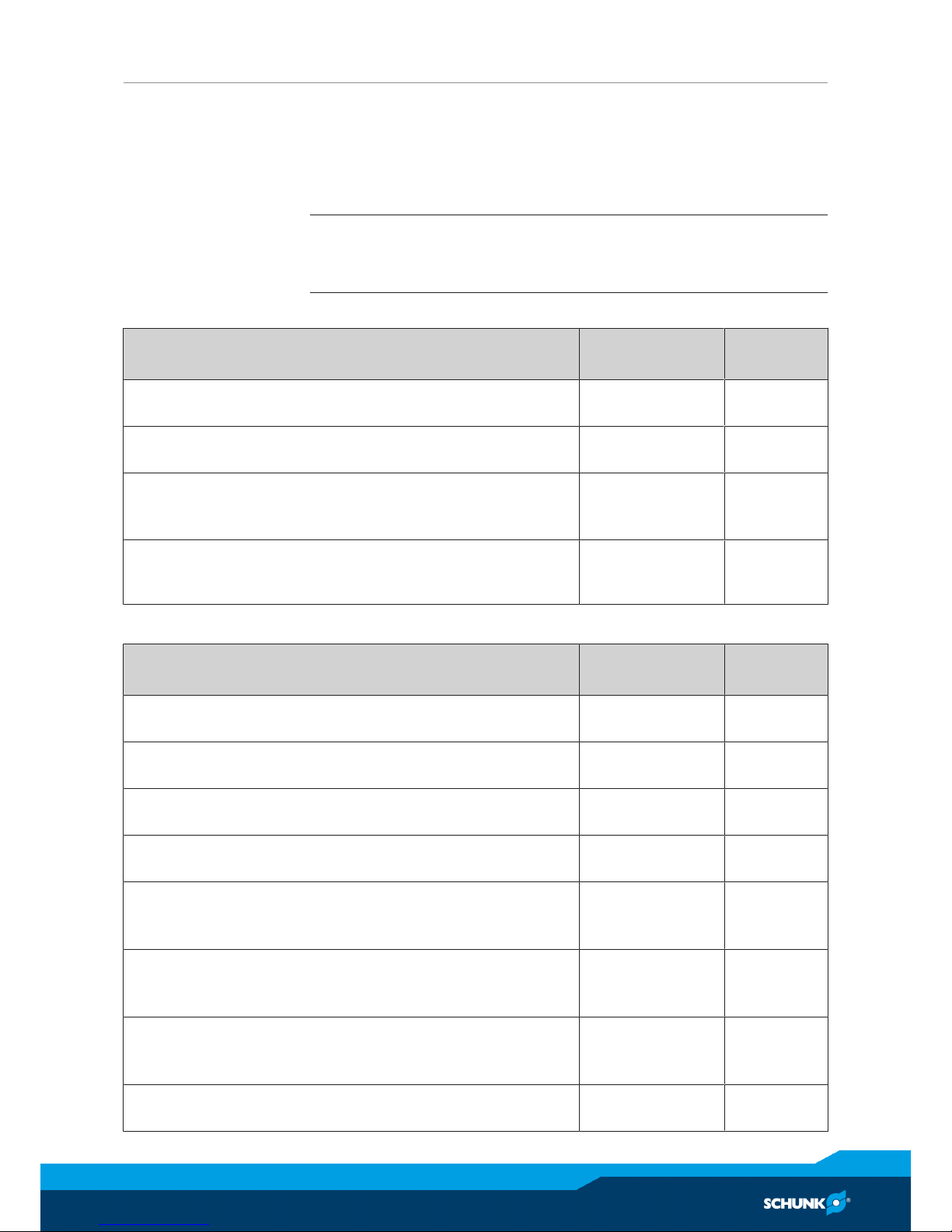
All fasteners used to mount the SWS-L to the robot and to user Tools
should be tightened to a torque value as indicated below. Furthermore, removable (blue) Loctite 242 must be used on these fasteners.
NOTE
Care should be taken to select fasteners for mounting that are not
too long, such that a gap is formed at the interface.
SWS-210
Mounting conditions Fastener Size and
Property Class
Recommended Torque
SWK-L to RIP (6061-T6 aluminum)
Minimum thread engagement of 15 mm (1.5 x fastener Ø)
M10–1.5
Class 12.9
75 Nm
SWK-L to Robot (steel; USS ≥ 90KSI)
Minimum thread engagement of 10 mm (1.0 x fastener Ø)
M10–1.5
Class 12.9
75 Nm
End-effector Interface Plate (aluminum) to SWA-L (7075T6 aluminum)
Minimum thread engagement of 15 mm (1.5 x fastener Ø)
M10–1.5
Class 12.9
52 Nm
End-effector Interface Plate (aluminum) to SWA-L (7075T6 aluminum)
Minimum thread engagement of 18 mm (1.5 x fastener Ø)
M12–1.75
Class 12.9
94 Nm
SWS-310
Mounting conditions
Fastener Size and
Property Class
Recommended Torque
SWK-L to Robot Interface Plate (6061-T6 aluminum)
Minimum thread engagement of 24 mm (1.5 x fastener Ø)
M16-2.0
Class 12.9
225 Nm
SWK-L to Robot Interface Plate (6061-T6 aluminum)
Minimum thread engagement of 18 mm (1.5 x fastener Ø)
M12-1.75
Class 12.9
95 Nm
SWK-L to Robot (steel; USS ≥ 90KSI)
Minimum thread engagement of 16 mm (1.0 x fastener Ø)
M16-2.0
Class 12.9
225 Nm
SWK-L to Robot (steel; USS ≥ 90KSI)
Minimum thread engagement of 12 mm (1.0 x fastener Ø)
M12-1.75
Class 12.9
95 Nm
End-effector Interface Plate (aluminum) to SWA-L (7075T6 aluminum)
Thread engagement of 21 mm (1.3 x fastener Ø)
M16-2.0
Class 12.9
225 Nm
End-effector Interface Plate (aluminum) to SWA-L (7075T6 aluminum)
Minimum thread engagement of 18 mm (1.5 x fastener Ø)
M12-1.75
Class 12.9
94 Nm
End-effector Interface Plate (aluminum) to SWA-L (7075T6 aluminum)
Minimum thread engagement of 15 mm (1.5 x fastener Ø)
M10-1.5
Class 12.9
52 Nm
SWA-L to End-effector Interface Plate (6061-T6 aluminum)
Minimum thread engagement of 15 mm (1.5 x fastener Ø)
M10-1.5
Class 12.9
52 Nm
Page 20
Installation
20
02.00 | SWS-L | Assembly and operating manual | en | 0389037
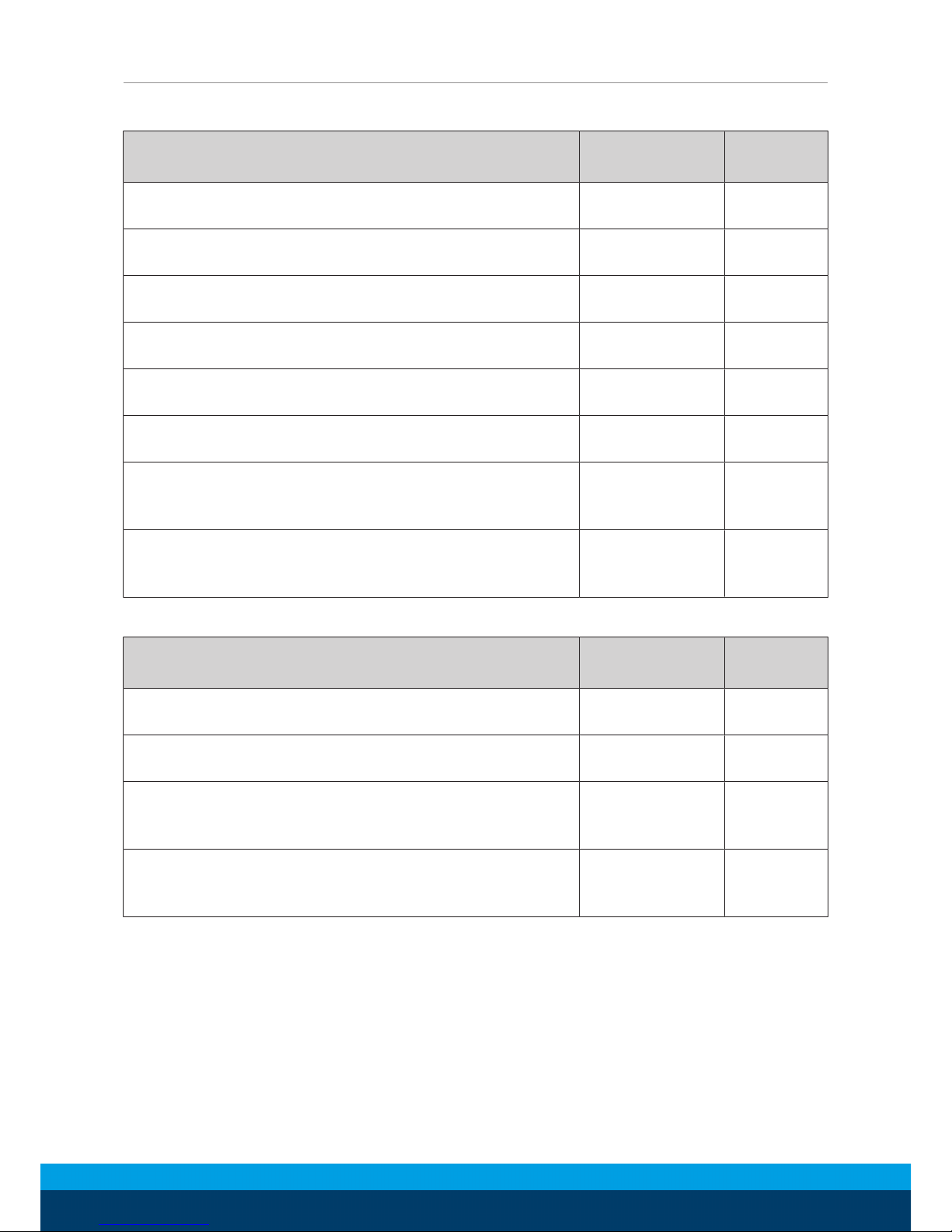
SWS-510
Mounting conditions Fastener Size and
Property Class
Recommended Torque
SWK-L to Robot Interface Plate (6061-T6 aluminum)
Minimum thread engagement of 24 mm (1.5 x fastener Ø)
M16-2.0
Class 12.9
325 Nm
SWK-L to Robot Interface Plate (6061-T6 aluminum)
Minimum thread engagement of 18 mm (1.5 x fastener Ø)
M12-1.75
Class 12.9
135 Nm
SWK-L to Robot Interface Plate (steel; USS ≥ 40KSI)
Minimum thread engagement of 24 mm (1.5 x fastener Ø)
M16-2.0
Class 12.9
325 Nm
SWK-L to Robot Interface Plate (steel; USS ≥ 40KSI)
Minimum thread engagement of 18 mm (1.5 x fastener Ø)
M12-1.75
Class 12.9
135 Nm
SWK-L to Robot (steel; USS ≥ 90KSI)
Minimum thread engagement of 16 mm (1.0 x fastener Ø)
M16-2.0
Class 12.9
325 Nm
SWK-L to Robot (steel; USS ≥ 90KSI)
Minimum thread engagement of 12 mm (1.0 x fastener Ø)
M12-1.75
Class 12.9
135 Nm
End-effector Interface Plate (steel or aluminum) to SWA-L
(7075-T6 aluminum)
Minimum thread engagement of 24 mm (1.5 x fastener Ø)
M16-2.0
Class 12.9
225 Nm
End-effector Interface Plate (steel or aluminum) to SWA-L
(7075-T6 aluminum)
Minimum thread engagement of 18 mm (1.5 x fastener Ø)
M12-1.75
Class 12.9
94 Nm
SWS-1210
Mounting conditions Fastener Size and
Property Class
Recommended Torque
SWK-L to RIP (6061-T6 aluminum)
Minimum thread engagement of 15 mm (1.5 x fastener Ø)
M10–1.5
Class 12.9
75 Nm
SWK-L to RIP (Steel; USS ≥ 90KSI)
Minimum thread engagement of 15 mm (1.5 x fastener Ø)
M10–1.5
Class 12.9
75 Nm
SWA-L (aluminum) to End-Effector Interface Plate (6061T6 aluminum)
Minimum thread engagement of 15 mm (1.5 x fastener Ø)
M10–1.5
Class 12.9
52 Nm
SWA-L (aluminum) to End-Effector Interface Plate (7075T6 aluminum)
Minimum thread engagement of 15 mm (1.5 x fastener Ø)
M10–1.5
Class 12.9
52 Nm
Page 21
Installation
02.00 | SWS-L | Assembly and operating manual | en | 0389037
21
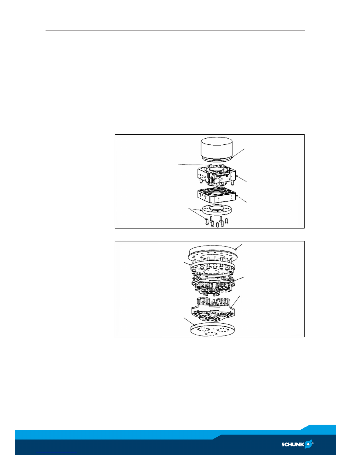
5.1 SWK-L
The SWK-L is attached to the robot arm. (SWS-L-1210: The SWK-L
is attached to the robot interface plate (RIP), and both are bolted
to the robot arm. The RIP is designed with mounting features such
as a boss and/or bolt and dowel holes.)
The SWK-L is designed with mounting features such as a boss and/
or bolt and dowel holes. These features are used to accurately position and secure the SWK-L to the robot. A robot interface plate
(RIP) is utilized to adapt the SWK-L to a specific robot flange that is
not compatible with the SWK-L mounting features. Custom RIPs
are available upon request.
Mounting Fastenres and
Dowel Pin
Customer Supplied
Tool Interface Plate,
Fasteners and Dowel Pins
Customer Supplied
Robot Arm
SWK-L
SWA-L
Typical Installation SWS-L-210, 310, 510
Robot Interface Plate
With Fasteners and
Dowel Pins
Tool Interface Plate
(Fasteners and Dowel Pins
not Shown)
Robot Wrist Flange
SWK-L with Fasteners to
Robot Interface Plate
SWA-L, with Fasteners to
Tool Interface Plate
Typical Installation SWS-L-1210
If the customer chooses to design and build a robot interface
plate, the following should be considered:
• The interface plate should be designed to include bolt holes for
mounting, dowel pins and a boss for accurate positioning on the
robot and SWK-L
• The thickness of the interface plate must be great enough to
provide the necessary thread engagement for the mounting bolts.
Page 22

Installation
22
02.00 | SWS-L | Assembly and operating manual | en | 0389037
• The interface plate must be properly designed to provide rigid
mounting to the SWK-L boss area.
• The plate design should take into account clearances required
for tool changer module attachments and accessories.
5.2 SWA-L
The SWA-L is attached to customer-supplied tooling. The SWA-L is
designed with mounting features such as a bolt and dowel holes.
These features are used to accurately position and secure the endeffector. Most often an End- effector Interface Plate (EIP) is utilized to adapt the SWA-L to an end-effector that is not compatible
with the SWA-L mounting features. Custom End-effector Interface
Plates can be supplied by SCHUNK to meet customer requirements
(refer to the drawings "Typical Installation" in the section above).
When the customer chooses to design and build an End- effector
Interface Plate, the following should be considered:
• The interface plate should be designed to include bolt holes for
mounting, dowel pins, and a boss that mates with SWA-L body
recess for accurate positioning.
• SWS-L-310: When using a locating boss, the race cover must be
removed.
• SWS-L-210: The locating boss height should not exceed 6.3mm.
If necessary, the race cover can be removed to allow for additional boss height.
• The thickness of the interface plate must be great enough to
provide the necessary thread engagement for the mounting bolts.
• The plate design should take into account clearances required
for SWS-L attachments and accessories.
• The End- effector Interface Plate should be designed with a hole
in its center to allow for manually returning the locking mechanism to the unlocked position under adverse conditions (i.e. unintended loss of power and/or air pressure). The center access
hole should be kept small (minimum recommended hole diameter: 25.4 mm) to prevent debris from contaminating the
locking mechanism while operating in dirty environments. Even
greater protection will result if the standard race cover with removable access plug is used. Note: Thru hole diameter in plate:
14.3 mm. Grommet outside diameter: 22.5 mm.
• SWS-L-1210: The End- effector Interface Plate should be designed with a set of holes in the center of each of the three locking mechanisms to allow for manually returning the locking
mechanisms to the unlocked position under adverse conditions
(i.e., unintended loss of power and/or air pressure). The center
access holes should be kept small (recommended hole diameter: 25.4mm) to prevent debris from contaminating the locking mechanism while operating in dirty environments.
Page 23

Installation
02.00 | SWS-L | Assembly and operating manual | en | 0389037
23
5.3 Tool Stand Design
NOTICE
Tool stand design is critical to proper operation of the SWS-L. Improperly designed tool stands can cause misalignments that will
cause jamming and/or excessive wear of SWS-L components.
SWS-L-1210: Z-Compliance is required for the Tool Stand, in or-
der to ensure that the SWK-L remains fully contacted with the
SWA-L prior to issuing the Unlock command.
NOTICE
During coupling and lock-up the tool stand must allow for
movement (float) in a plane parallel to the mating surfaces of
the SWK-L and SWA-L, and in a direction perpendicular to this
plane, towards the SWK-L.
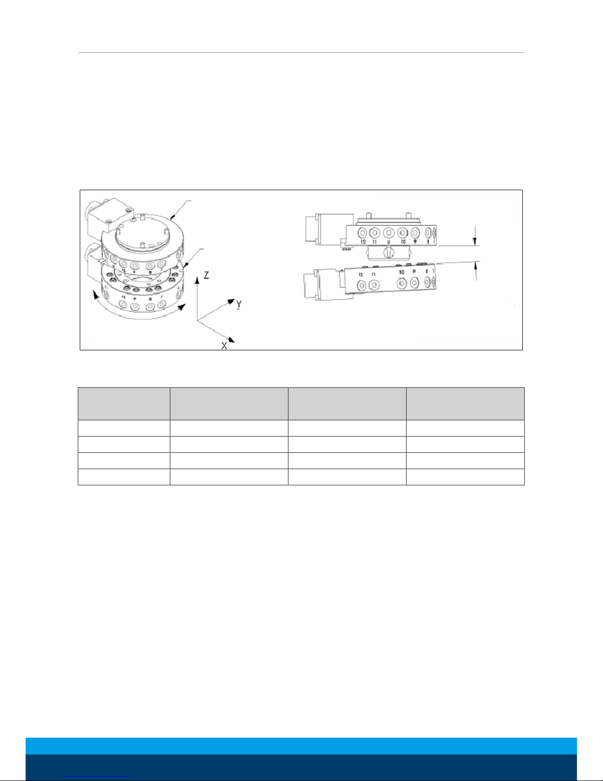
In most cases, the SWA-L are stored in a Tool Stand when not being used by the robot. During coupling and lock-up, the Tool Stand
must allow for movement (float) in a plane parallel with the mating surfaces of the SWK-L and SWA-L (X and Y directions). Even
slight misalignment between the SWK-L and SWA-L can generate
high forces during lockup if the SWA-L is not allowed to float into
place during lock-up. These high forces can cause excessive wear
and even jamming of the end-effector and robot. The degree of
float required depends on the accuracy of the robot’s positioning
and the repeatability of the SWA-L location in the Tool Stand during lock-up. See following Figure and Table for recommended maximum allowable float (offsets) prior to coupling. The Tool Stand
should be designed to minimize misalignment during coupling and
uncoupling. In some cases, greater offsets than shown in the Table
can be accommodated by the SWK-L and SWA-L, but will increase
wear.
Ideally, the SWA-L should be hanging vertically in the tool stand so
that gravity acts to uncouple the SWA-L from the SWK-L during unlocking.
SWS-L-1210:, the Tool stand should have compliance in the Z direction. The robot should be programmed to fully seat the SWA-L in
the Tool Stand before issuing the Unlock command. The Unlock
sensors need to be active before pulling the SWK-L away.
It is possible to design Tool Stands that hold SWA-L in the horizontal position, but care must be taken that the necessary compliance is provided during coupling and uncoupling. In general, “horizontalposition” Tool Stands cause more wear on the locking mechanism and locating features of the SWA-L and Tool Stand.
Page 24
Installation
24
02.00 | SWS-L | Assembly and operating manual | en | 0389037
Lock-up should occur with the SWK-L in the No-Touch™ locking
zone (see following table), but not touching the SWK-L. As locking
occurs, theSWK-L should draw the SWA-L into the locked position.
Tool Stands may also need to incorporate means for covering tools
and electrical modules to protect them in dirty environments, such
as grinding or welding. Alternatively, locating Tool Stands in areas
shielded from weld spatter, fluids, adhesives, or other debris
would eliminate the need for tool covers.
SWK-L
SWA-L
Twisting
Cocking Offset
(About X and Y)
X, Y and Z Offset
Offset Definitions
Maximum Recommended Offsets Prior to Coupling
Model No-Touch™ Zone Z
Offset (Max)* (mm)
X and Y Offset (Max)**
(mm)
Cocking Offset (Max)
(degrees)
SWS-L-210 2.5 ±2 ±1
SWS-L-310 2.5 ±2 ±1
SWS-L-510 2.5 ±2 ±1
SWS-L-1210 1 ±2 ±1
* Maximum values shown. Decreasing actual values will minimize wear during coupling/
uncoupling.
** Actual allowable values may be higher in some cases but higher offsets will increase
wear during coupling.
Page 25
Operation
02.00 | SWS-L | Assembly and operating manual | en | 0389037
25
6 Operation
The SWK-L locking mechanism is pneumatically driven to couple
and uncouple with the bearing race on the SWA-L. The SWK-L utilizes air ports from a signal control module or air supply block to
provide lock and unlock pressure to the locking mechanism.
CAUTION
Safe, reliable operation of the Tool Changer is dependent on a
continuous supply of compressed air at a pressure of 4,1 bar to
7 bar [SWS-L-1210: 4,9 bar to 6,9 bar]
Robot motion should be halted if the air supply pressure drops
below 4,1 bar [SWS-L-1210: 4,9 bar] for any reason.
NOTICE
All SWS-L are initially lubricated using MobilGrease® XHP222
Special grease.
• The end user must apply additional lubricant to the locking
mechanism components and alignment pins prior to start of service Cleaning, Lubrication, Adjustment and Replacement. Tubes
of lubricant for this purpose are shipped with every SWS-L.
• Note: MobilGrease® XHP222 Special is a NLGI #2 lithium com-
plex grease with molybdenum disulfide.
6.1 Coupling Sequence
NOTICE
Possible damage to the unit and/or the robot, if the locking
mechanism is not in unlock position when attemting to couple
the SWS-L.
• The locking mechanism must be in the unlock position when
attempting to couple the SWS-L.
Position the SWK-L above the Tool and move the SWK-L into locking position. When using electrical feed-through-modules the
voltages from 24 V have to be switched off prior to coupling. Contacts could be damaged due to sparking. Coupling without power
shutdown may shorten the life extremely. The mating surfaces of
the SWK-L and Tool should be parallel and not touching. Make
sure that the tapered alignment pins from the SWK-L enter the
alignment holes on the Tool. The alignment pins should be relatively concentric with the alignment holes such that they do not rub
against the edge.
Page 26

Operation
26
02.00 | SWS-L | Assembly and operating manual | en | 0389037
The locking mechanism allows the SWK-L to “pull up” the Tool with
relatively large gaps between the two sides. It is recommended
that the mating faces of the SWK-L and Tool not be touching, but
be within 1 mm of each other when coupling to minimize stress
and wear on the locking mechanism.
RTL (Ready-To-Lock) sensing is built into the tool changer, providing the ability to sense Tool proximity to the SWK-L prior to locking. The mating faces of the SWK-L and Tool must be positioned
within approximately 1.40–1.65 mm [SWS-L-510: 0.50–0.75 mm]
of each other for the sensors to detect Tool presence. RTL signals
are not required to couple the tool changer, but are recommended
as a further confirmation of coupling prior to removing the Tool
from the tool stand.
NOTICE
No-TouchTM locking technology allows the unit to couple with a
separation distance between the SWK-L and Tool. Direct contact
of the SWK-L and SWA-L mating surfaces is not suggested or required just prior to coupling. (SWS-L-1210: ONLY if Z compliance
is built in to the Tool Stand.) Contact may result in damage to
the unit and/or the robot.
Verify that the RTL signals are read as “on” (true).
Turn the Lock command on. Air is supplied to the locking mechan-
ism to couple the SWS-L.
SWS-L-1210: Turn the Unlatch output off. Turn the Latch output
on. Air is supplied to the locking mechanism to couple the SWS-L.
A sufficient delay must be programmed between the Lock com-
mand being activated and reading the state of the Locked/Unlocked signals, so that the locking process is completed before
checking the locked state.
Read the Locked and Unlocked signals.
The Locked signal should read “on” (true) and the Unlocked signal
should read “off” (false).
If the locking mechanism has been actuated and both the Locked
and Unlocked signals are read as “off” (false), then a “missed tool”
condition has occurred (for example, the SWA-L is not in the stand
or is not positioned properly). In this case, an error should be generated and the robot program halted. The situation requires
manual inspection to determine the cause of the problem.
The locking mechanism must be in the unlocked state before another attempt is made to couple or damage could occur to the robot and/or the SWS-L.
Page 27

Operation
02.00 | SWS-L | Assembly and operating manual | en | 0389037
27
6.2 Fail-Safe Operation
In the event of air supply loss to the locking mechanism the SWS-L
will not uncouple.
A slight separation between the SWK-L and SWA-L occurs just after
air loss, but at this point the locking balls become trapped and cannot move without air pressure being applied to the unlock port.
This feature provides the SWS-L with a fail-safe mechanism.
The patented fail-safe design prevents the SWA-L from being released in the event of air-pressure loss to the Lock port, thereby
increasing safety and reliability. Positional accuracy may not be
maintained during air loss but will be regained once air pressure is
reestablished to the Lock port.
NOTICE
Possible damage to the locking mechanism
• Do not use the SWS-L in the fail-safe condition for extended
periods of time. Do not transport the SWS-L in the fail-safe
condition.
6.3 Uncoupling
The SWS-L should be positioned in the Tool Stand in the same location as when coupling took place. When using electrical feedthrough-modules the voltages from 24 V have to be switched off
prior to uncoupling. Contacts could be damaged due to sparking.
Uncoupling without power shutdown may shorten the life extremely.
SWK-L-1210: Verify that the Tool is FULLY secured and seated in
the Tool Stand. Z-compliance is required for the Tool Stand in order to ensure reliable Unlocking sequence. Once you have verified
that the SWA-L is FULLY secured in the Tool Stand, turn the Latch
output off.
NOTICE
This SWS-L may be equipped with a Tool Stand Interlock (TSI)
feature that physically breaks the unlock solenoid circuit. Use of
the TSI will prevent any unwanted unlock software commands
from being recognized until the circuit is made.
• See user manual of the respective control module for details
and troubleshooting.
Page 28

Operation
28
02.00 | SWS-L | Assembly and operating manual | en | 0389037
SWS-L-210-510: Turn the Lock output off (for double solenoid
valve versions).
SWS-L-210: Issue the Unlock output. / SWS-L-310, 510: Issue the
Unlock command. / SWS-L-1210: Issue the Unlatch output. Air is
supplied to the locking mechanism to uncouple the SWS-L.
A sufficient delay must be programmed between the Unlock output being activated and reading the state of the Lock/Unlock signals, so that the coupling process is completed before checking the
Locked state.
Read the Locked and Unlocked signals.
The Unlock signal should read “on” (true) and the Lock signal
should read “off” (false). Any other condition indicates a problem
and the robot program should be halted.
Once the Lock and Unlock signals are verified to be in the proper
state the SWK-L may be moved away from the SWA-L in the axial
direction.
SWS-L-1210: Check to verify that the RTLs are all “off” (false) after
the SWK-L moves away from the SWA-L.
The robot and SWK-L can now proceed to another SWA-Lfor coupling and subsequent operations.
Page 29
Operation
02.00 | SWS-L | Assembly and operating manual | en | 0389037
29
6.4 Integrated Sensors (SWS-L-1210)
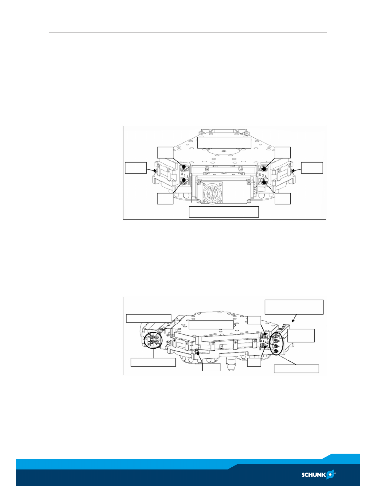
The SWK-L-1210 has a total of 6 proximity sensors for detecting
the Lock and Unlock state of the SWS-L. For each locking mechanism there is one Lock sensor and one Unlock sensor. Each sensor
pair is distinguished by the corresponding locking mechanism. For
example, locking mechanism #1 has “L1” (Lock sensor #1) and
“U1” (Unlock sensor #1). Also, to eliminate confusion, the SWK-L
body, sensor cables, and junction module connectors are labeled
the same way (L1, U1, L2, U2, L3, and U3).
SWK-L 1210
U1
RS1
L1
Flat A / Control Module
U3
RS3
L3
Lock and Unlock sensors. "L2" and "U2" not visible in this view
Inside the junction module, all 3 Lock sensors are wired in series
which provides for one Locked signal via the connector labeled “L”.
The 3 Unlocked sensors are also wired in series within the junction
module which provides for one Unlocked signal via the connector
labeled “U”. Cables connect the “L” and “U” connectors of the
junction module to the “L” and “U” connectors of the control module.
Control Module
SWK-L-1210
U2
U1, L1, U2, and L2
(not visible in this view)
Junction
Module
R1, R2, U and L
RS3
L2
U3, L3, U and L
Connector view
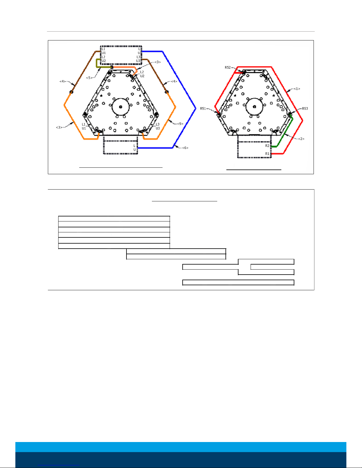
The following figure and table show the cables pertaining to the
Lock and Unlock sensors. From the factory, the cables will be
labeled to match where they are connected.
Page 30
Operation
30
02.00 | SWS-L | Assembly and operating manual | en | 0389037
Junction
Module
Air Valve
Control/Signal
Module
Air Valve
Control/
Signal
Module
Lock & Unlock Sensor Cables
RTL Sensor Cables
Sensor Cable Routing
Sensor Cable Routing
Lock/Unlock Sensor
ID
Junction Module
Connector
#
#
L1
L2
L3
U1
U2
U3
<3>
<3>
<3>
<3>
<3>
<3>
<4>
<5>
<4>
<4>
<5>
<4>
L1
L2
L3
U1
U2
U3
L
U
#
<6>
<6>
L
U
R1
R2
9121-XXX-M
Control Module
Connector
<1>
<2>
#
RS1
RS2
RS3
RTL Sensor ID
The SWK-L-1210 has 3 RTL sensors.
They are designated as “RS1”, “RS2”, and “RS3”. Sensors “RS1” and
“RS2” are wired in series (by means of a splitter cable) and in this
way provide the control module with a single “R1” signal.
Only when “RS1” and “RS2” are both triggered will a Tool presence
signal occur at “R1”.
The third RTL sensor, “RS3”, is connected directly to the control
module at “R2” to give a second Tool presence signal. show the
cables pertaining to the RTL sensors. The labels on the cables indicate which sensors the cables are connected to.
Page 31
Troubleshooting
02.00 | SWS-L | Assembly and operating manual | en | 0389037
31
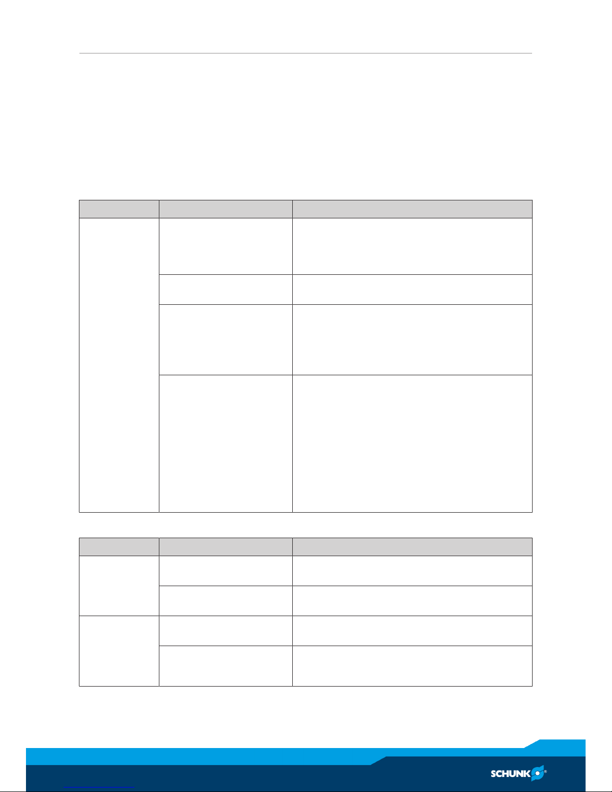
7 Troubleshooting
Check these conditions for all symptoms prior to troubleshooting:
• Proper pneumatic and electrical connections have been made
to the SWS-L.
• Air is supplied at a minimum of 5 and a maximum of 6,9 bar.
• No air or vacuum can be trapped in a de-energized Lock or Unlock port (pressure must be vented to atmosphere).
SWS-L-210, 310, 510
Symptom Cause Resolution
Unit will not
lock or unlock
The ball bearings and/or
cam are not moving
freely in the male coupling.
Clean and lubricate as needed to restore
smooth operation Maintenance.
The control module is not
operating correctly.
Check the troubleshooting section of the
manual for the specific module.
The SWK-L and SWA-L are
not within the specified
No-Touch zone when attempting to lock.
Check that the Tool is properly seated in the
Tool Stand.
Re-teach the robot to bring the SWK-L and
SWA-L closer together prior to attempting to
lock.
Ready-To-Lock (RTL)
sensors not activated indicating Tool is not positioned properly
Check that the SWA-L is properly seated in the
tool stand.
Re-teach the robot to bring the SWK-L and
SWA-L closer together prior to attempting to
lock.
Check that both RTL sensors are not damaged.
Replace damaged RTL sensors as necessary.
Check all cables for damage and that they are
connected properly to the signal control module. Replace damaged cables as necessary.
SWS-L-310 and 510
Symptom Cause Resolution
Unit is locked
but Lock signal
does not read
“on” (true).
Lock sensor is damaged. Replace Lock sensor or Sensor Assembly as ne-
cessary Maintenance.
Lock sensor is out of position.
Replace the Lock sensor or Sensor Assembly as
necessary.
Unit is unlocked but Unlock signal
does not read
“on” (true).
Unlock sensor is damaged Replace Unlock sensor Or Sensor Assembly as
necessary Maintenance.
Unlock sensor is out of
position
Replace Unlock sensor or Sensor Assembly as
necessary.
Page 32

Troubleshooting
32
02.00 | SWS-L | Assembly and operating manual | en | 0389037
SWS-L-210
Symptom Cause Resolution
Unit is locked
but Lock signal
does not read
“on” (true).
Lock sensor/cable is damaged.
Units using individual Sensors: Replace Lock
sensor/cable as necessary Maintenance.
Units using Sensor Assemblies: Replace the
lock sensor sub-assembly as necessary.
Lock sensor is out of position.
Units using individual Sensors: Adjust Lock
sensor using procedure in Maintenance.
Units using Sensor Assemblies: Replace the
lock sensor sub-assembly as necessary.
Unit is unlocked but Unlock signal
does not read
“on” (true).
Unlock sensor/cable is
damaged.
Units using individual Sensors: Replace Unlock
sensor/cable as necessary Maintenance.
Units using Sensor Assemblies: Replace the
unlock sensor sub-assembly as necessary.
Unlock sensor is out of
position
Units using individual Sensors: Adjust Unlock
sensor using procedure in Maintenance
Units using Sensor Assemblies: Replace the
unlock sensor sub-assembly as necessary.
SWS-L-1210
Symptom Cause Resolution
Unit will not
Lock or Unlock
or the locking
mechanisms
are jammed.
The ball bearings and/or
cam are not moving
freely in the male coupling.
Clean and lubricate as needed to restore
smooth operation Maintenance.
The SWK-L and SWA-L are
not within the specified
No-Touch zone when attempting to Lock.
Check that the SWA-L is properly seated in the
Tool Stand. Reteach the robot to bring the
SWK-L and SWA-L closer together before attempting to Lock.
SWK-L and SWA-L are not
parallel (all three RTL
sensors are not on when
trying to lock).
Check that the SWA-L is properly seated in the
Tool Stand. Reteach the robot to bring the
SWK-L and SWA-L closer together and parallel
prior to attempting to Lock.
Verify RTLs (RS1, RS2, and RS3) are all on.
SWA-L Drop-off Distance
is too large.
Check that the SWA-L is properly positioned in
the Tool Stand and the SWA-L is fully seated.
Check that the UNLATCH command is not being
issued with the SWA-L sitting above the Tool
Stand and the robot is not trying to “drop” the
SWA-L into the nest.
Page 33

Troubleshooting
02.00 | SWS-L | Assembly and operating manual | en | 0389037
33
Symptom Cause Resolution
Unit is fully
locked but
Locked input
to control
module is not
ON
Individual Lock sensor/
cable damage.
Check LED light on each of the three Lock
sensors.
If OFF check for cable damage and a secure
connection to the junction module. Replace
sensor and/or cable as needed.
Main Lock sensor/cable
damage.
are on, check the main Lock cable connecting
the junction module and control module.
NOTE: Individual sensors are wired in series in
the junction module. All sensors must be “on”
to get the main Lock input “on”.
Check for cable damage and a secure connection to control module. Replace as needed.
Junction Module failure. If individual Lock sensors/cables and main Lock
cable are found to be good, replace junction
module.
Unit is fully unlocked but Unlock input to
control module
is not ON.
Individual Unlock sensor/
cable damage.
Check LED light on each of the three Unlock
sensors.
If OFF check for cable damage and a secure
connection to the junction module. Replace
sensor and/or cable as needed.
Main Unlock sensor cable
damage.
If all individual Unlock sensor LEDs are on,
check the main Unlock cable connecting the
junction module and control module. NOTE: Individual sensors are in series in the junction
module. All sensors must be “on” to get the
main Unlock input “on”.
Check for cable damage and a secure connection to control module. Replace as needed.
Junction Module failure. If individual Unlock sensor/cables and main Un-
lock cable are found to be good, replace control module.
R1 input (RS1
and RS2
sensors) not
on.
SWK-L not in position. Reprogram pick-up point so SWK-L and SWA-L
are parallel and within 1 mm of each other.
Sensor/cable damage. Check the RS1 and RS2 sensor faces and cables
for damage. Replace if necessary.
NOTE: These sensors are wired in series in the
cable harness. Both sensors must be “on” to
get the R1 (RTL1) input “on”.
Check splitter cable from R1 connector at the
control module to RS1 and RS2 sensors. Replace as needed.
Page 34

Troubleshooting
34
02.00 | SWS-L | Assembly and operating manual | en | 0389037
Symptom Cause Resolution
R2 input (RS3
sensor) not on.
SWK-L not in position at
Pickup.
Reprogram pick-up point so SWK-L and SWA-L
are parallel and within 1 mm of each other.
Sensor/cable damage. Check the RS3 sensor face for damage. Replace
if necessary.
Check cable between RS3 sensor and the R2
connector at control module for damage and
replace as needed.
Page 35

Maintenance and Care
02.00 | SWS-L | Assembly and operating manual | en | 0389037
35
8 Maintenance and Care
NOTE
The cleanliness of the work environment strongly influences the
error-free operation of the change system. If the work environment is prone to heavy contamination, it is very important that
the entire unit is protected from contamination with appropriate
measures.
Protective measures:
• Locate toolholders at a distance from sources of dust
• Include protective equipment in the storage rack (install deflectors, air curtains or similar equipment on the unit Requirements of the storage magazine)
8.1 Preventive Maintenance
The Tool Changer and optional modules are designed to provide a
long life with regular maintenance.
A visual inspection and preventive maintenance schedule is
provided in the table below depending upon the application.
Detailed assembly drawings, Assembly drawings [}52].
NOTE
All Tool Changers are initially lubricated using MobilGrease®
XHP222 Special grease. The end-user must apply additional lubricant to the locking mechanism components and alignment pins
prior to start of service Link Schmierstoffe/Schmierstellen.
For this purpose, tubes of lubricant are shipped with every Tool
Changer.
NOTE:
MobiGrease® XHP222 Special is a NLGI#2 lithium complex grease
with molybdenum disulfide.
Page 36

Maintenance and Care
36
02.00 | SWS-L | Assembly and operating manual | en | 0389037
Schedule
Application(s) Tool Change Frequency Inspection Schedule
General Usage
Material Handling
Docking Station
> 1 per minute Weekly
General Usage
Material Handling
Docking Station
< 1 per minute Monthly
Welding/Servo/Deburring
Foundry Operations (Dirty Environments)
All Weekly
Checklist
Balls/Alignment
Pins/Holes/Bearing
Race
Inspect for lubrication and wear. A NLGI #2, lithium-based grease
with molybdenum disulfide additive is suggested for locking mechanism and alignment pin lubrication. Over time, lubricants can become
contaminated with process debris. Therefore, it is recommended to
thoroughly clean the existing grease and replace with new as
needed. Link Schmierstoffe/Schmierstellen.
Excessive alignment pin/bushing wear may be an indication of poor
robot position during pickup/drop-off. Adjust robot position as
needed. Check Tool Stand for wear and alignment problems.
Wear on the balls/bearing race could be an indication of excessive
loading.
Mounting Hardware /
/Interface Connections
Inspect for proper torque and interference or wear, abrasions, cuts
of hoses, and electrical cables. Tighten and correct as required.
Seals Inspect for wear, abrasion, and cuts.
Exposed O-rings and rubber bushings may be subject to damage during normal operation. Replace damaged o-rings and rubber bushings
as needed.
Sensors and Cables Inspect sensor cables and connectors for any damage, cuts, and ab-
rasion.
Electrical Contacts/
Pin Block (Modules)
Inspect for wear and abrasion.
Exposed contacts may be subject to damage during normal opera-
tion.
Clear debris from the area of the contacts using compressed air.
Do not directly clean contacts as abrasion may occur and the per-
formance of the contact may be compromised.
Page 37
Maintenance and Care
02.00 | SWS-L | Assembly and operating manual | en | 0389037
37
8.2 Cleaning, Lubrication, Adjustment and Replacement
8.2.1 Cleaning and Lubrication of the Locking Mechanism
8.2.1.1 Cleaning and Lubrication of the Locking Mechanism and
Alignment Pins
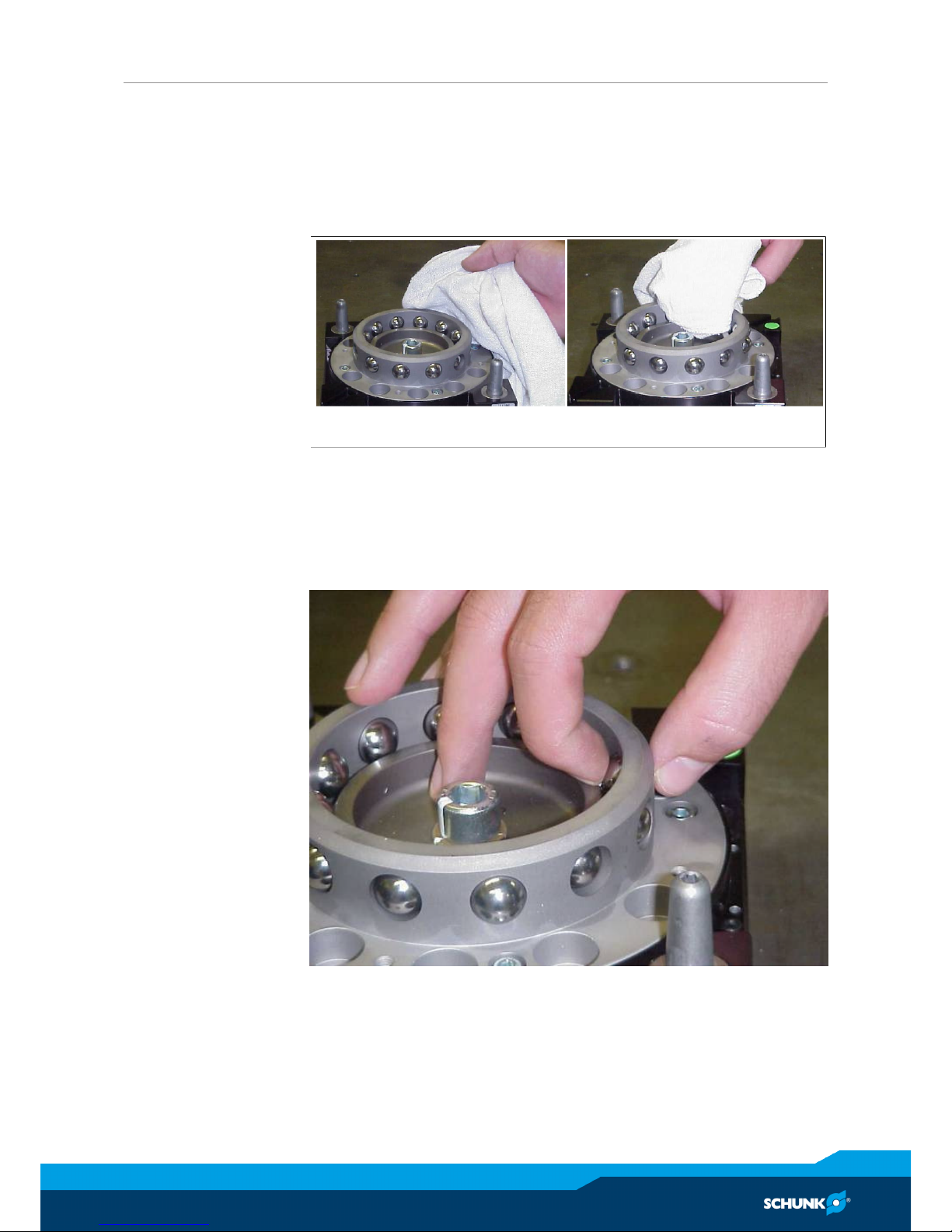
Cleaning balls and outer
surfaces of male coupling
Cleaning balls, cam an inner
surfaces of male coupling
Ø The locking mechanism must be in the unlock state before
cleaning.
Ø Use a clean rag to thoroughly remove the existing lubricant and
debris from the balls, the male coupling, the cam and the alignment pins.
Ø Check each ball to make sure it moves freely in the male coup-
ling. Additional cleaning may be necessary to free up any balls
that are sticking in place.
Page 38
Maintenance and Care
38
02.00 | SWS-L | Assembly and operating manual | en | 0389037
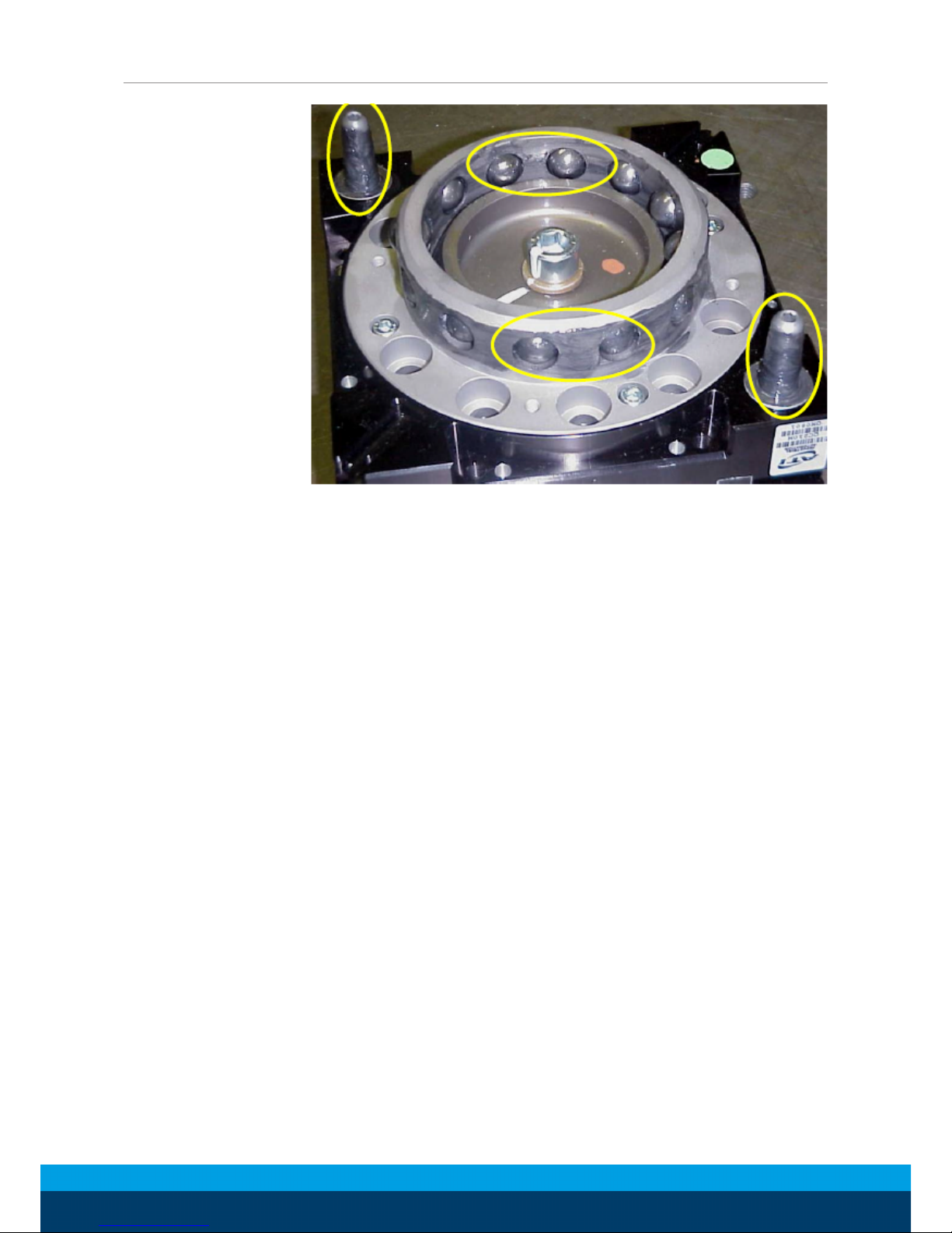
Ø Apply a liberal coating of lubricant to the balls, the male coup-
ling (inside and out), and the alignment pins.
8.2.1.2 Cleaning the Bearing Race and Alignment Pin Bushings (SWA)
1. Use a clean rag to thoroughly remove any lubricant and debris
from the bearing race and the bushings.
2. No re-lubrication is necessary on the SWA components.
Page 39
Maintenance and Care
02.00 | SWS-L | Assembly and operating manual | en | 0389037
39
8.2.2 Lock and Unlock Sensor Assembly Replacement
8.2.2.1 SWS-L-210
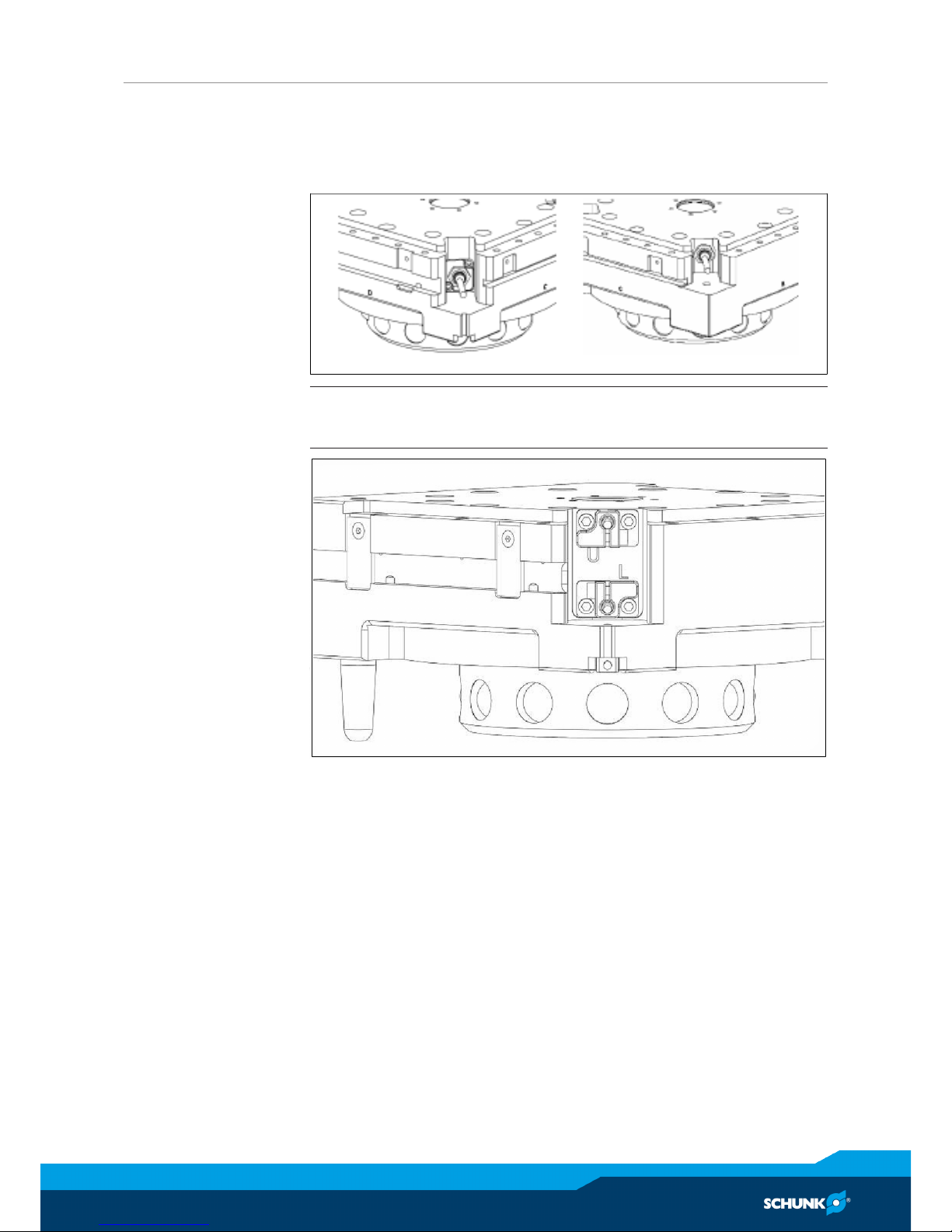
Sensor types
Determine what type of sensors the SWS-L uses:
Units using Sensor Assemblies
Units using Individual Sensors
NOTE
Turn air off before servicing sensors.
Units using Sensor assemblies
Lock and Unlock Sensor Assembly Replacement
Ø Unscrew the sensor cable connector from the control/signal
module.
Ø If present, remove the module(s) on the flat D.
Ø Remove the two M3 socket head cap screws that secure the as-
sembly to the SWK-L body.
Ø Slide the sensor assembly out and discard. Visually check that o-
ring around sensor was removed with assembly.
CAUTIONThe Lock and Unlock sensor assemblies are precision
aligned and permanently assembled at the factory. Do not attempt to disassembled and re-build.
Ø Apply Loctite 222MS to the new M3 socket head cap screws
supplied with the new sensor assembly.
Ø Attach the new assembly to the SWK-L body by tightening the
M3 screws to 1.36 Nm of torque.
Ø Re-attach cables and modules.
Page 40
Maintenance and Care
40
02.00 | SWS-L | Assembly and operating manual | en | 0389037
Ø Confirm operation of the Unlock sensor by issuing the Unlock
command and then checking to see that the LED in the Unlock
sensor body is on.
Ø Confirm operation of the Lock sensor by issuing the Lock com-
mand to lock a Tool to the SWK-L and then checking to see that
the LED in the Lock sensor body is on.
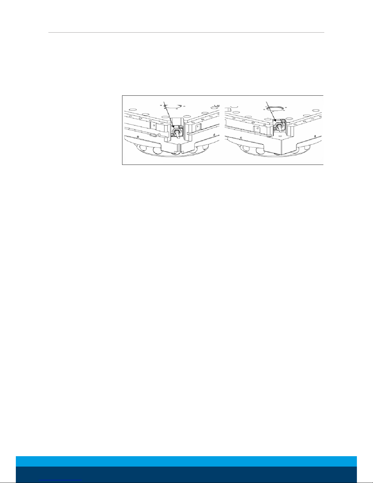
Units using indidivual
sensors
Lock sensor assembly
Unlock sensor assembly
Lock and Unlock sensor assemblies SWS-L-210
Ø Unscrew the sensor cable connector from the control/signal
module.
Ø For Lock sensor assembly replacement, remove any modules
mounted on Flat D. For Unlock sensor assembly replacement,
remove any modules mounted on both Flats C and D.
Ø Remove the two M4 socket head cap screws that secure the as-
sembly to the SWK-L Body.
CAUTIONThe Lock and Unlock sensor assemblies are precision
aligned and permanently assembled at the factory. Do not attempt to disassemble and rebuild. Over-tightening the proximity sensor on the jam nut will cause severe damage to the
SWK-L.
Ø Slide the sensor assembly out and discard.
Ø Apply Loctite 222MS to the new M4 socket head cap screws
supplied with the new sensor assembly.
Ø Attach the new assembly to the SWK-L body by tightening the
M4 screws to 3.39 Nm of torque.
Ø Re-attach cables and modules.
Ø Confirm operation of the Unlock sensor by issuing the Unlock
command and then checking to see that the LED in the Unlock
sensor body is on.
Ø Confirm operation of the Lock sensor by issuing the Lock com-
mand to lock a SWA-L to the SWK-L and then checking to see
that the LED in the Lock sensor body is on.
Page 41

Maintenance and Care
02.00 | SWS-L | Assembly and operating manual | en | 0389037
41
8.2.2.2 SWS-L-310 (Model Designator: SWK-L-310DM-...SM)
Lock and Unlock Sensor Assembly Replacement
1. Unscrew the sensor cable connector from the control/signal
module.
2. If present, remove the module(s) on the flat D.
3. Remove the two (2) M3 socket head cap screws that secure the
assembly to the SWK-L body.
4. Slide the sensor assembly out and discard. Visually check that o-
ring around sensor was removed with assembly.
NOTICE
The Lock and Unlock sensor assemblies are precision aligned
and permanently assembled at the factory. Do not attempt to
disassembled and re-build.
5. Apply Loctite 222MS to the new M3 socket head cap screws
supplied with the new sensor assembly.
6. Attach the new assembly to the SWK-L body by tightening the
M3 screws to 1.36 Nm of torque.
7. Re-attach cables and modules.
8. Confirm operation of the Unlock sensor by issuing the Unlock
command and then checking to see that the LED in the Unlock
sensor body is on.
9. Confirm operation of the Lock sensor by issuing the Lock
command to lock a SWA-L to the SWK-L and then checking to
see that the LED in the Lock sensor body is on.
Page 42
Maintenance and Care
42
02.00 | SWS-L | Assembly and operating manual | en | 0389037
8.2.2.3 SWS-L-310 and 510
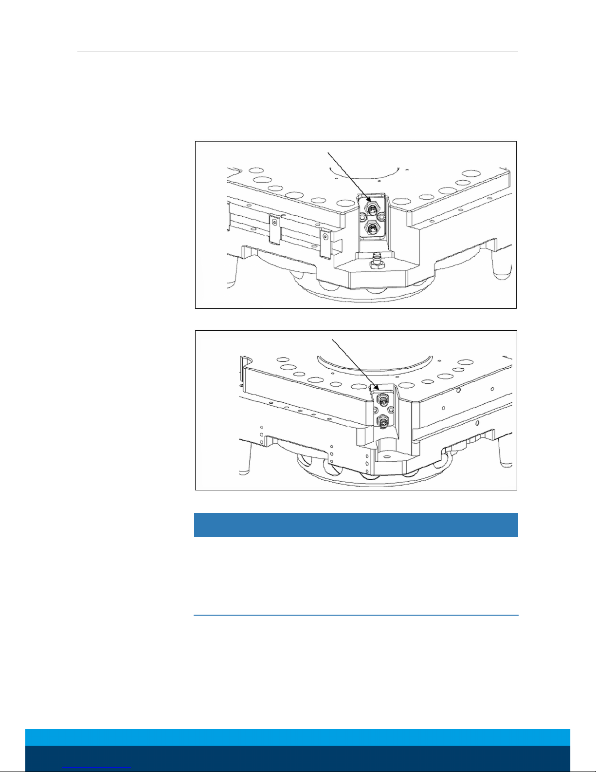
• SWS-L-310: Units using a dual-sensor assembly P/N: 9951094
Set for INB 310 U/L incl. plate for preadjusting
• SWS-L-510: Units using Lock/Unlock sensor assembly P/N:
9005-20-1339 (PNP)
Lock/Unlock sensor assembly
Lock/Unlock sensor assembly SWS-L-310
Lock/Unlock sensor assembly
Lock/Unlock sensor assembly SWS-L-510
NOTICE
The Lock/Unlock sensor assembly is precision aligned and permanently assembled at the factory. Do not attempt to disassemble and re-build.
SWS-L-310: Over tightening the proximity sensor or the jam nut
will cause severe damage to the SWK-L.
Ø Unplug the sensor cable connectors from lock and unlock sensors.
Ø Remove the two M4 socket head cap screws that secure the as-
sembly to the SWK-L body.
Ø Slide the sensor assembly out and discard.
Page 43
Maintenance and Care
02.00 | SWS-L | Assembly and operating manual | en | 0389037
43
Ø Apply Loctite 222MS to the M4 socket head cap screws supplied
with the new sensor assembly.
Ø Slide the assembly into position and secure it to the SWK-L body
by tightening the M4 screws to 3.39 Nm of torque.
Ø Re-attach cables.
Ø Confirm operation of the Unlock sensor by issuing the Unlock com-
mand and verifying that the LED in the Unlock sensor body is on.
Ø Confirm operation of the Lock sensor by issuing the Lock com-
mand to lock a Tool to the SWK-L and verifying that the LED in
the Lock sensor body is on.
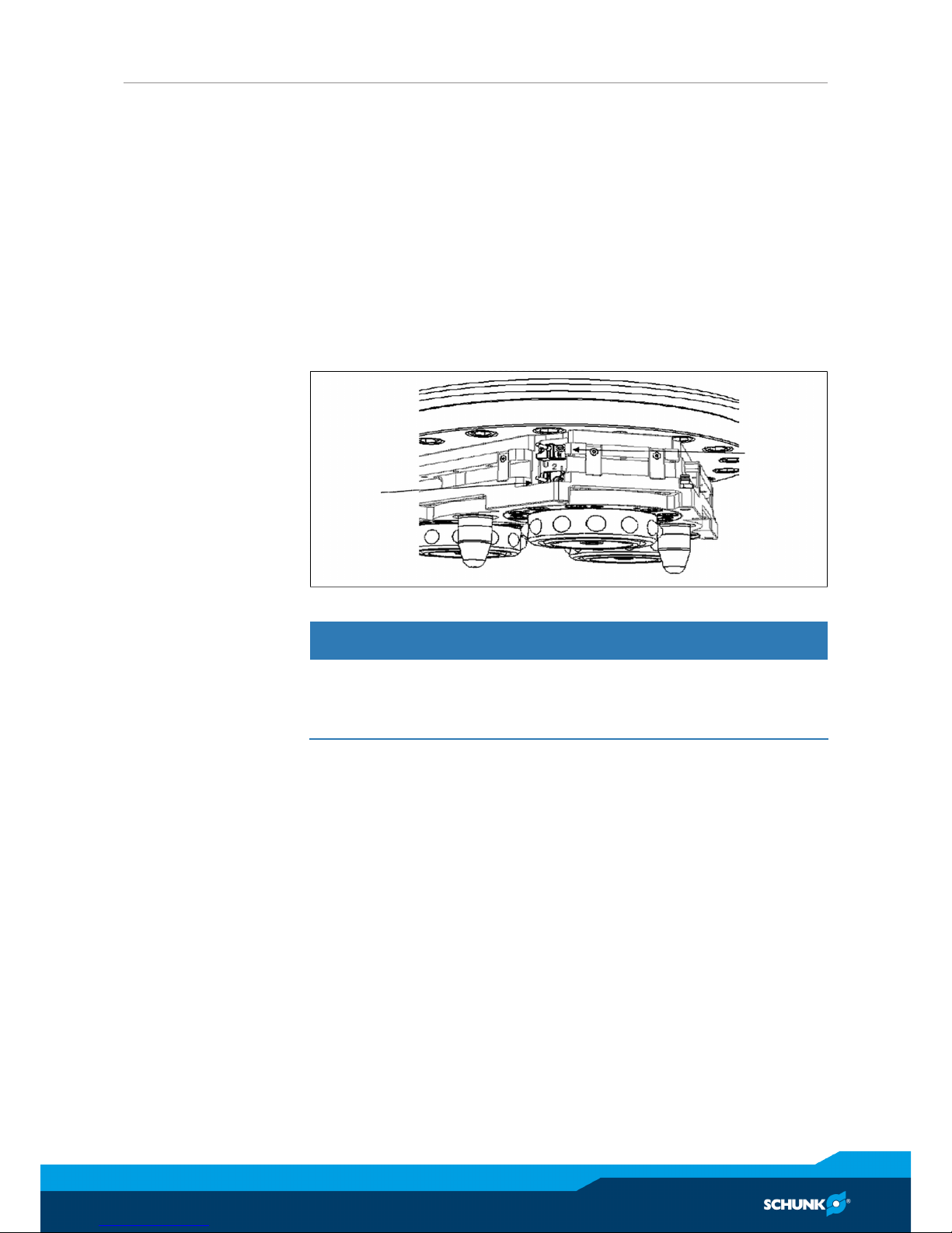
8.2.2.4 SWS-L-1210
Lock Sensor
Assembly
(3 Places)
Unlock
Sensor
Assembly
(3 Places)
Lock and Unlock Sensor Assemblies SWS-L-1210
NOTICE
The Lock and Unlock sensor assemblies are precision aligned and permanently assembled at the factory. Do not attempt to adjust the position of the sensor or severe damage to the SWK-L may occur.
Ø Unscrew the sensor cable connector from the extension cable.
Ø Remove the two M3 socket head cap screws that secure the as-
sembly to the SWK-L body.
Ø Slide the sensor assembly out and discard.
Ø Apply Loctite 222MS to the new M3 socket head cap screws
supplied with the new sensor assembly.
Ø Check that the new sensor assembly has the o-ring present and
that the old oring came off of the SWK-L with the old sensor assembly. Attach the new assembly to the SWK-L by tightening
the M3 screws to 1.36 Nm.
Ø Re-attach cables and modules.
Ø Confirm operation of the Unlock sensor by issuing the Unlatch
command and then checking to see that the LED in the Unlock
sensor body is on.
Page 44
Maintenance and Care
44
02.00 | SWS-L | Assembly and operating manual | en | 0389037
Ø Confirm operation of the Lock sensor by issuing the Latch com-
mand to lock a Tool to the SWK-L and then checking to see that
the LED in the Lock sensor body is on.
8.2.3 Lock/Unlock Sensor Adjustment and Replacement (Units using
individual sensors)
8.2.3.1 SWS-L-210
NOTICE
Over tightening the proximity sensor or the jam nut will cause
severe damage ! to the SWK-L.
NOTE
When adjusting the lock sensor the SWK-L must be locked to the
Tool. When adjusting the unlock sensor the SWK-L must be separated from the Tool and in the unlocked condition.
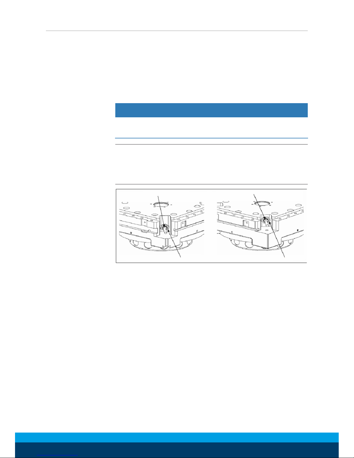
Lock sensor
Jam nut
Unlock sensor
Jam nut
Individual Lock and Unlock sensors SWS-L-210
Ø Loosen jam nut with slotted 13mm socket or standard pliers.
Ø Turn proximity sensor clockwise until the LED in the sensor body
comes on.
Ø Turn the proximity sensor clockwise another 1/4 turn (90°).
Ø Tighten jam nut to 2.26 Nm of torque.
Page 45
Maintenance and Care
02.00 | SWS-L | Assembly and operating manual | en | 0389037
45
8.2.3.2 SWS-L-310 and 510
NOTICE
Over tightening the proximity sensor or the jam nut will cause
severe damage ! to the SWK-L.
NOTE
• Do not undertake this adjustment until proper operation of the
sensor has been confirmed. This requires removing the sensor
from the SWK-L and testing it separately from the EOAT.
• When adjusting the lock sensor the SWK-L must be locked to
the Tool.
• When adjusting the unlock sensor the SWK-L must be separated
from the Tool and in the unlocked condition.
Unlock sensor
Jam nut
Lock sensor
Jam nut
Lock and Unlock sensors in body - SWS-L-310
Unlock sensor
Jam nut
Lock sensor Jam nut
Lock and Unlock sensors in body - SWS-L-510
Ø Loosen jam nut with 13mm socket or standard pliers.
Ø Turn proximity sensor clockwise until the LED in the sensor body
comes on.
Ø Turn the proximity sensor clockwise another 1/4 turn (90°).
Ø Tighten jam nut to 2.26 Nm of torque.
Page 46

Maintenance and Care
46
02.00 | SWS-L | Assembly and operating manual | en | 0389037
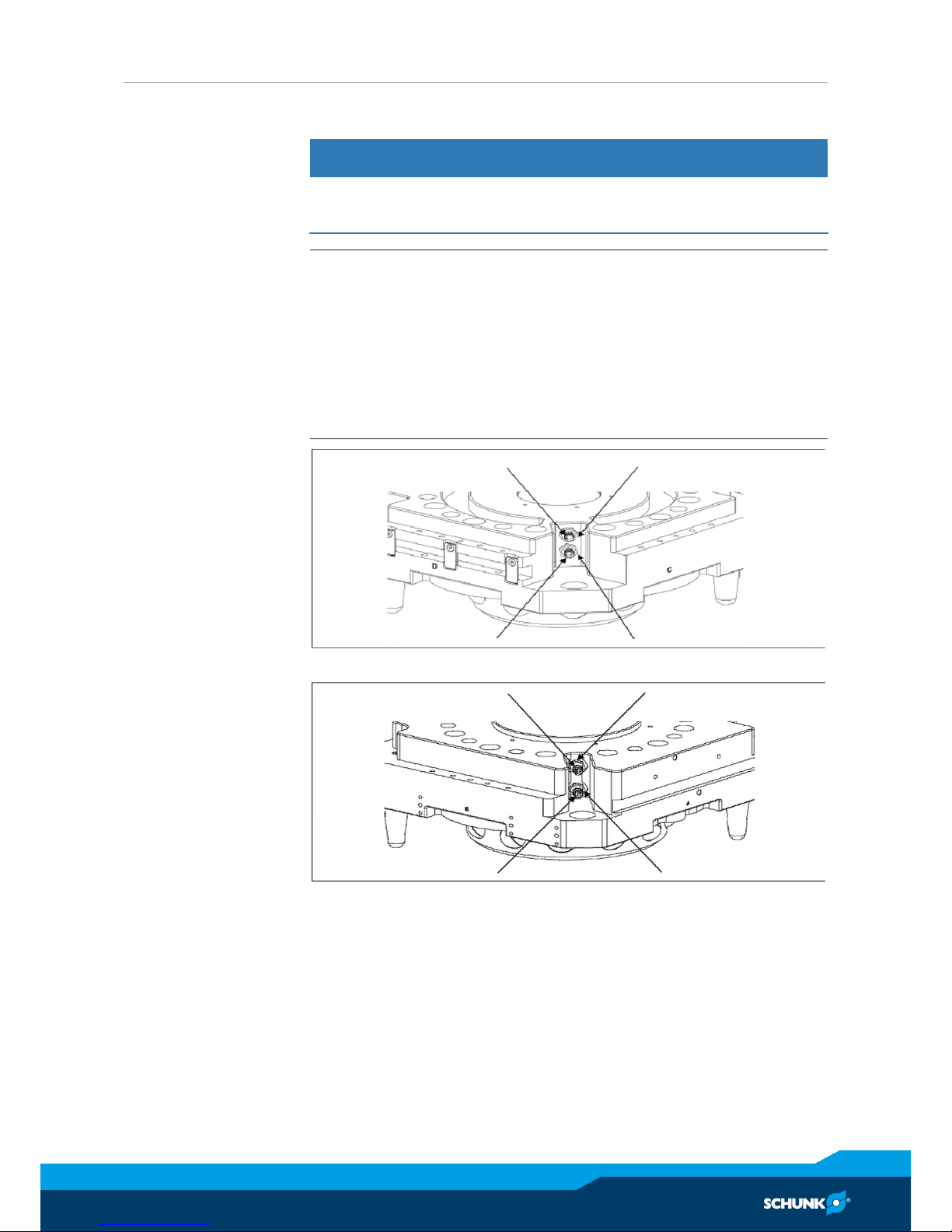
8.2.4 RTL Sensor Replacement
8.2.4.1 SWS-L-210
RTL Sensor Replacement (Flat Pack style)
Ø Unscrew the sensor cable connector from the control/signal
module.
Ø Unscrew the M3 socket flat head cap screw that fastens the
sensor to the SWK-L body.
Ø For replacement of the RTL sensor between flats A and B re-
move the cleat assembly on flat A (This may require that the
SWK-L be removed from the robot.). For replacement of the RTL
sensor between flats A and B remove the module and cable retaining tabs mounted on flat D.
Ø Remove the sensor/cable assembly from the SWK-L and discard.
Ø Install the new sensor/cable assembly. Use Loctite 222MS on
the screws securing the sensors and the cable retaining tabs.
Ø Re-attach cables and modules.
Ø Confirm operation of the new sensor by bringing a metallic ob-
ject into close proximity to the face of the sensor and watching
for the LED in the body of the sensor to come on.
RTL Sensor Replacement (8mm Threaded Barrel Style)
Ø Unscrew the sensor cable connector from the control/signal
module.
Ø Remove the cleat assembly on flat A (This may require that the
SWK-L be removed from the robot.).
Ø Loosen the jam nut securing the sensor to the SWK-L body
Ø Remove the sensor/cable assembly from the SWK-L and discard.
Ø Screw the new sensor/cable assembly into the SWK-L body until
the face of the sensor is flush with the surrounding face of the
SWK-L body. Use a slotted socket and a torque wrench to
tighten the jam nut to 20 in-lbs of torque.
Ø Re-install the cleat on flat A. Use Loctite 222MS on the screws.
Ø Re-attach the cable connector to the control/signal module.
Ø Confirm operation of the new sensor by bringing a metallic ob-
ject into close proximity to the face of the sensor and watching
for the LED in the body of the sensor to come on.
Page 47
Maintenance and Care
02.00 | SWS-L | Assembly and operating manual | en | 0389037
47
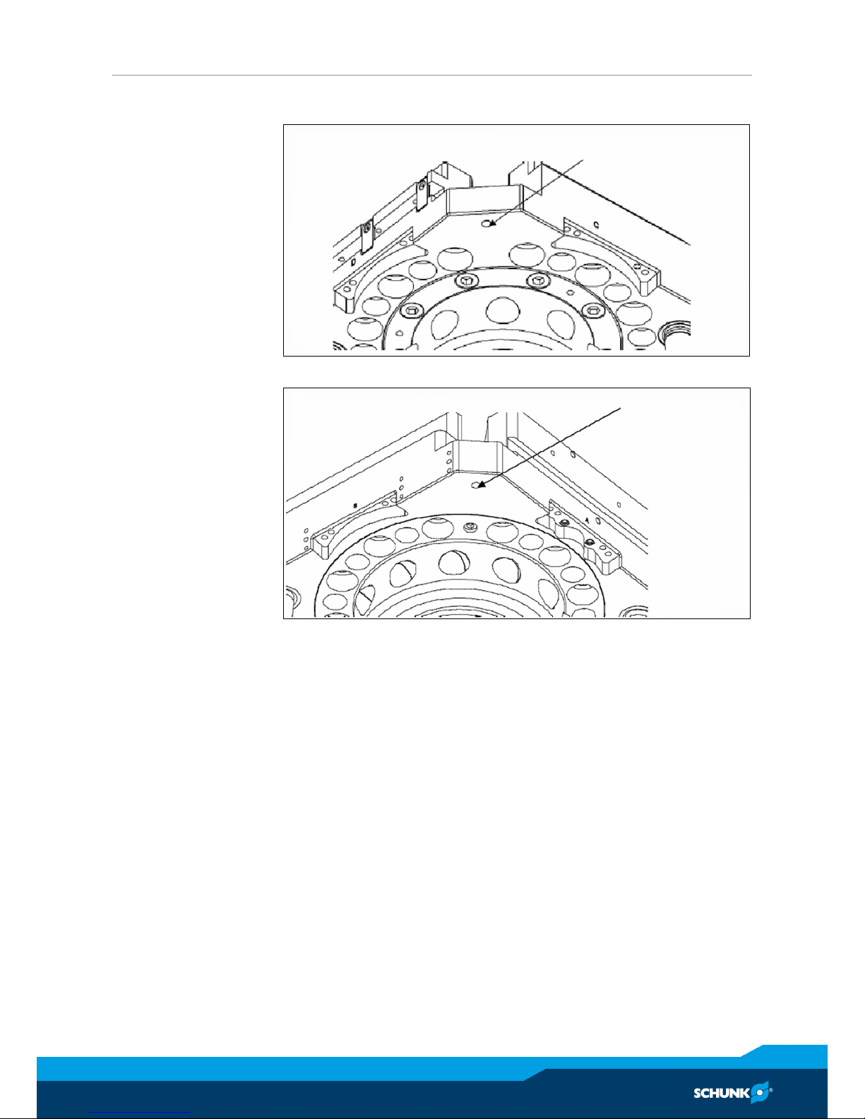
8.2.4.2 SWS-L-310 and 510
RTL Sensor (1 of 2)
RTL sensor - SWS-L-310
RTL sensor (1 of 2)
RTL sensor - SWS-L-510
1. Unplug the cable from the RTL sensor.
2. Loosen the jam nut securing the sensor to the SWK-L body.
3. Remove the sensor from the SWK-L and discard.
4. Screw the new sensor into the SWK-L body until the face of the
sensor is flush with the surrounding face of the SWK-L body.
Use a socket and a torque wrench to tighten the jam nut to 2.26
Nm of torque.
5. Attach the cable to the new RTL sensor.
6. Confirm operation of the new sensor by bringing a metallic
object into close proximity to the face of the sensor and
watching for the LED in the body of the sensor to come on.
Page 48
Maintenance and Care
48
02.00 | SWS-L | Assembly and operating manual | en | 0389037
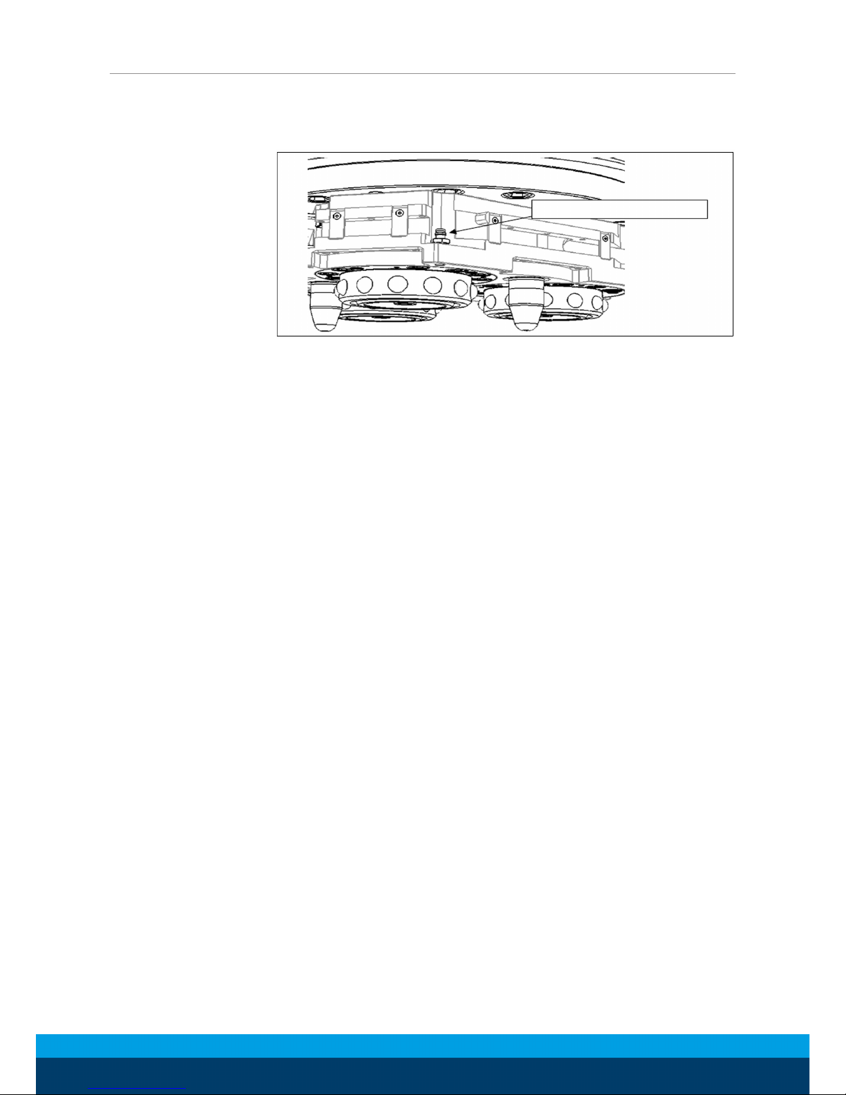
8.2.4.3 SWS-L-1210
RTL Sensor Replacement (8mm Threaded Barrel Style)
1 of 3 Ready-To-Lock Sensors
Barrel-style RTL sensor - SWS-L-1210
Ø Remove the sensor cable connector from the sensor.
Ø Loosen the jam nut securing the sensor to the SWK-L body.
Ø Unscrew/remove the sensor from the SWK-L and discard.
Ø Screw the new sensor/cable assembly into the SWK-L body until
the face of the sensor is flush with the surrounding face of the
SWK-L body. Turn the sensor back ¼ turn. Use a crowfoot and a
torque wrench to tighten the jam nut to 2.26 Nm of torque.
Ø Replace the sensor cable if needed.
Ø Re-attach the cable connector to the control/signal module.
Ø Confirm operation of the new sensor by bringing a metallic ob-
ject into close proximity to the face of the sensor and watching
for the LED in the body of the sensor to come on. NOTICE: “R1”
consists of sensors “RS1” and “RS2” wired in series. Therefore, a
metallic object has to be used at both locations in order to view
the LED indicator of either sensor SWS-1210: Integrated
Sensors .
Page 49

Maintenance and Care
02.00 | SWS-L | Assembly and operating manual | en | 0389037
49
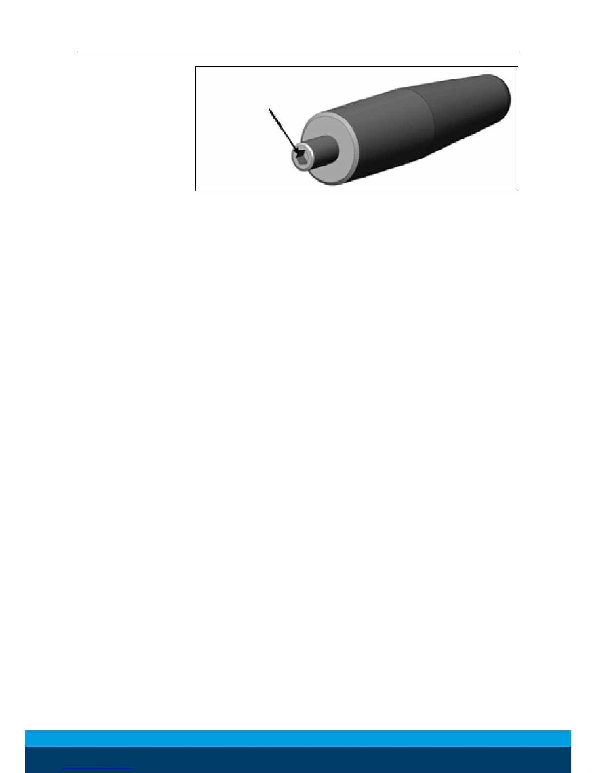
8.2.5 Alignment Pin Replacement
8.2.5.1 SWS-L-210 - 510
Removing the
Alignment Pin
4mm
Hex Key
4mm Hex Key - SWS-L-210 - 510
Ø Unscrew the alignment pin sub-assembly from the SWK-L using
a 4mm hex key (see Figure above).
Note: If for any reason the pin cannot be removed using the hex
socket in the tip, it may be necessary to remove it by other
means, such as Vise Grip pliers.
3mm
Hex Key
3mm Hex Key - SWS-L-210
Page 50
Maintenance and Care
50
02.00 | SWS-L | Assembly and operating manual | en | 0389037
4mm
Hex Key
4mm Hex Key - SWS-L-310, 510
✓ Another approach would be to use the access hole in the
back side of the SWK-L. In this case, a hex key will be needed
( 3 mm for SWS-210 / 4mm for SWS-310 and 510) (see Figures above).
Ø Once the alignment pin has been removed, verify that the sub-
assembly (pin and set screw) are intact. If the set screw portion
of the subassembly did not come out, it will be necessary to remove it separately using the access hole in the back plate of the
SWK-L.
Installing the Alignment Pin Assembly
into the SWS-L
Ø Apply Loctite 242 and install the Alignment Pin Assembly into
the Bushing on the SWS-L. Tighten to 6.78 Nm.
Ø Apply MobilGrease® XHP222 Special grease to the Alignment
Pin Cleaning and Lubrication of the Locking Mechanism
8.2.5.2 SWS-L-1210 (1-1/8” Two Piece Pin Sub-Assembly)
Ø Unscrew the alignment pin sub-assembly from the SWK-L using
a 5mm hex key. Note: If for any reason the pin cannot be removed using the hex socket in the tip, it may be necessary to remove it by other means such as Vise Grip pliers. Another approach is to use the access hole in the back side of the SWK-L. In
this case, a 4 mm hex key will be needed.
Ø Once the alignment pin has been removed verify that the sub-
assembly (pin and set screw) is intact. If the set screw portion of
the sub-assembly did not come out it will be necessary to remove it separately using the access hole in the back side of the
SWK-L.
Ø Apply Loctite® 242 (or similar thread locking compound) to the
M8 set screw in the new alignment pin.
Ø Install the alignment pin into the bushing and screw it into
place. Apply 60 in-lb of torque to fully tighten it.
Page 51
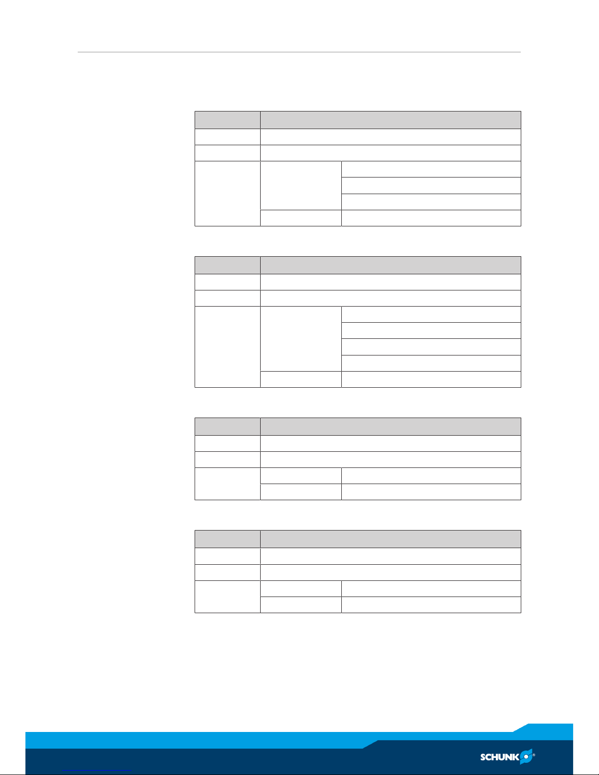
Maintenance and Care
02.00 | SWS-L | Assembly and operating manual | en | 0389037
51
8.3 Recommended Spare Parts
8.3.1 SWS-L-210
Assembly Description
SWK-L Complete SWK-L-210, No Options
SWA-L Complete SWA-L-210, No Options
Other Sensors 2x Lock and Unlock sensors
1x RTL1
1x RTL2
Alignment Pin 2x Alignment Pin
8.3.2 SWS-L-310
Assembly Description
SWK-L Complete SWK-L-310, No Options
SWA-L Complete SWA-L-310, No Options
Other Sensors 1x Set
2x RTL
3x Cables with connectors 0,33m
1x Cable with connector 0,4m
Alignment Pin 2x Alignment Pin
8.3.3 SWS-L-510
Assembly Description
SWK-L Complete SWK-L-510, No Options
SWA-L Complete SWA-L-510, No Options
Other Sensors Sensors complete
Alignment Pin Alignment Pin
8.3.4 SWS-L-1210
Assembly Description
SWK-L Complete SWK-L-1210, No Options
SWA-L Complete SWA-L-1210, No Options
Other Sensors Sensors complete
Alignment Pin Alignment Pin
Page 52
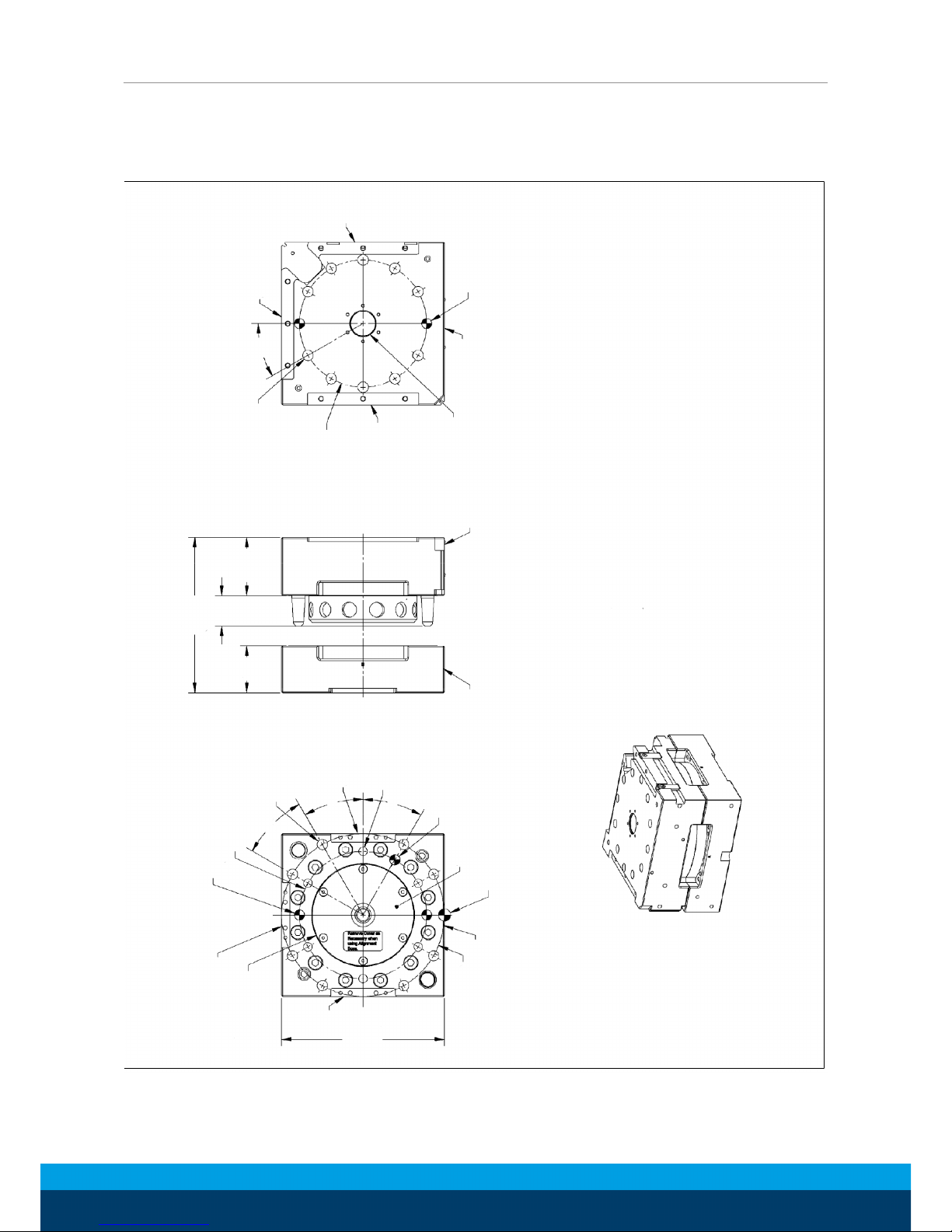
Maintenance and Care
52
02.00 | SWS-L | Assembly and operating manual | en | 0389037
8.4 Assembly drawings
8.4.1 SWS-L-210
Flat D
Flat C
(2) Ø 10 (Slip Fit)
Equally Spaced
Customer Interface
Flat A
Master Side
(projection only)
30°
(10) C'Bored 10.6 Dp.
From Far Side
for M10 SHCS
30° Spacing-Skip Ø10 dowel
Customer Interface
B.C. Ø 125
Flat B
See Note 2
[4.06"]
103.1
Coupled
30
Pin
57.1
SWK-L
46.1
SWA-L
SWK-L Side
SWA-L Side
160
Square
SWK-L
& SWA-L
B.C. Ø 160
Flat A
Ø 12 (Slip Fit), 12 Dp.
Customer Interface
(with air block spacer installed)
Tool Cover
Ø 10 (Slip Fit), 12 Dp.
Customer Interface
30°
(6) Tapped M10X1.5
20 Dp.
Equally Spaced
Customer Interface
Flat B
(4) 30°
(8) Tapped M12X1.75
18 Dp.
Customer Interface
(4) 30°
Customer Interface
B.C. Ø 125
(2) Ø10 (Slip Fit), 20 Dp.
Equally Spaced
Flat C
Ø 100 H7, 8 Dp.
(See Note 1)
Customer Interface
Flat D
SWA-L Side
(projection only)
Scale 1:2.5
Notes:
1) Tool cover must be removed to utilize full depth of this customer interface feature.
With tool cover in place usable feature depth is 2mm.
2) Optional SWK-L side mounting bosses available.
SWS-L 210
Page 53
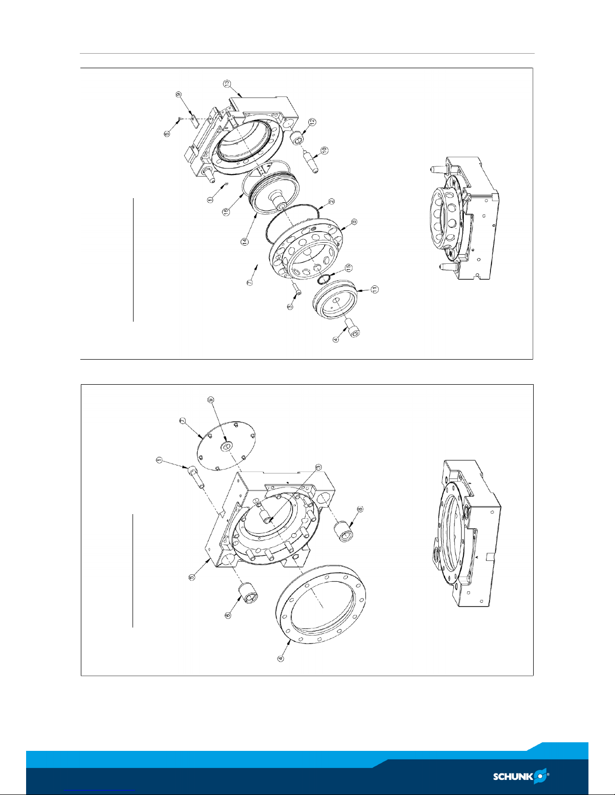
Maintenance and Care
02.00 | SWS-L | Assembly and operating manual | en | 0389037
53
SWK-L-210 Master Assembly
SWK-L-310
SWA-L-210 Tool Assembly
SWA-L-210
Page 54
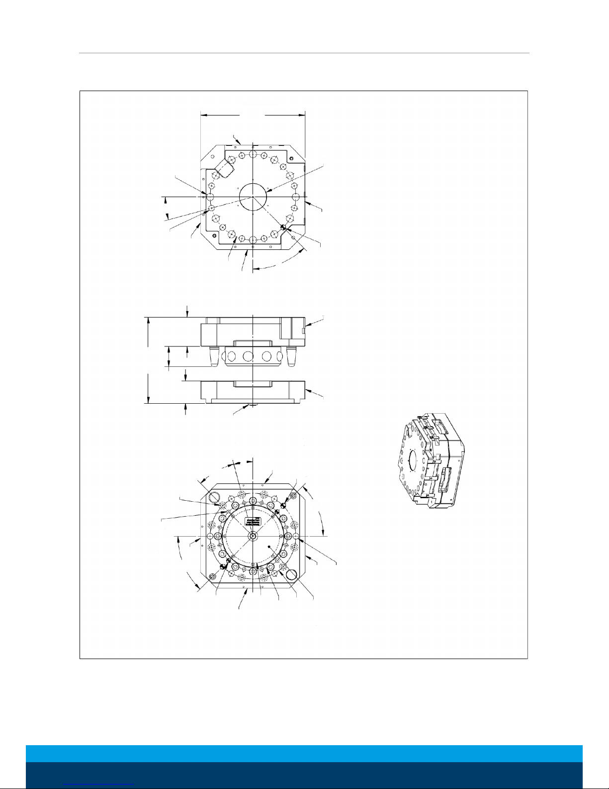
Maintenance and Care
54
02.00 | SWS-L | Assembly and operating manual | en | 0389037
8.4.2 SWS-L-310
244
Square
SWK-L &
SWA-L
See Note 1
Flat A
Ø 12 (Slip Fit)
18 Dp.
Customer Interface
45°
Flat B
B.C. Ø200
Flat C
(10) C'Bored 14.5 Dp.
From Far Side
for M12 SHCS
30° Spacing-Skip Ø 12 Dowel
& Location Opposite
Customer Interface
15°
(12) C'Bored 16.4 Dp.
From Far Side
for M16 SHCS
Equally Spaced
Customer Interface
Flat D
[4.72"]
120
Coupled
47.2
Pin
68.1
SWK-L
52.1
SWA-L
See Note 4
(A)
(B)
Flat B
(2) Ø 12 (Slip Fit)
18 Dp.
Equally Spaced
Customer interface
45°
(6) Tapped M16x2.0
See Table 1 for Thread Depth
Equally Spaced
Customer Interface
Flat A
Tool Cover
B.C Ø200
B.C. Ø 160
Ø125 H7, 5 Dp.
(See Note 3)
Customer Interface
Flat D
(2) Ø10 (Slip Fit)
16 Dp.
Equally Spaced
Customer Interface
45°
Flat C
(10) Tapped M10x1.5, 19 Dp.
30° Spacing
Skip Ø10 Dowels
Customer Interface
(10) Tapped M12x1.75, 20 Dp.
30° Spacing
Skip Ø 12 Dowels
Customer Interface
(Optional Bolt Down Note 2)
30°
Typ.
15°
Scale 1:4
Part Numbers:
(A) SWK-L: 9121-310AMX-0-0-0-0
(B) SWA-L: 9121-310DT-0-0-0-0
Notes:
1) Center Boss inserts available
2) Optional Bolt Down: (10) Holes C'Bored from opposite side 10.2 deep for M10 SHCS.
3) Tool cover must be removed to utilize this customer interface feature.
4) Remove plug if necessary to avoid interface with customer tooling.
Assembly drawing SWS-L 310
Page 55
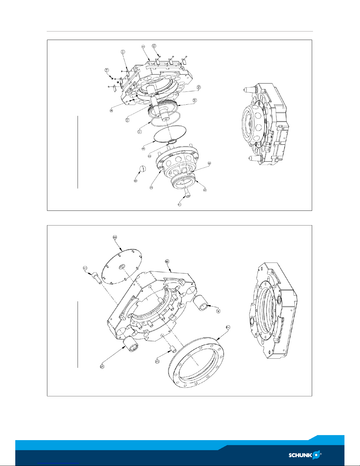
Maintenance and Care
02.00 | SWS-L | Assembly and operating manual | en | 0389037
55
SWK-L-310 Master Assembly
SWK-L-310
SWA-L-310 Tool Assembly
SWA-L-310
Page 56

Maintenance and Care
56
02.00 | SWS-L | Assembly and operating manual | en | 0389037
8.4.3 SWS-L-510
Flat D
264
Square
SWK-L &
SWA-L
Flat A
30°
Typ.
15°
(10) C'Bored 15.6 Dp.
From Far Side
for M12 SHCS
30° Spacing-Skip Ø 12 Dowel
& Location Opposite
Customer Interface
Flat B
B.C. Ø200
Flat C
(12) C'Bored 16.4 Dp.
From Far Side
for M16 SHCS
Equally Spaced
Customer Interface
45°
Ø 12 Slip Fit
13 Dp.
Customer Interface
Ø 125
Slip fit
Customer
Interface
6.4
Boss
54.7
Pin
[5.57"]
141.5
Coupled
82.7
SWK-L
58.8
SWA-L
(B)
(A)
30°
Typ.
15°
(5) Tapped M12x1.75
29 Dp.
Equally Spaced
(Counter Clockwise)
Customer Interface
Flat A
(12) Tapped M16x2.0
29 Dp.
Equally Spaced
Customer Interface
Flat D
30°
Typ.
15°
(5) Tapped M12x1.75
29 Dp.
Equally Spaced
(Counter Clockwise)
Customer Interface
(2) Ø12 Slip Fit, 13 Dp.
Equally Spaced
Customer Interface
45°
Flat C
Ø125 H7, 6.5 Dp.
Customer Interface
B.C Ø200
Flat B
SWA-L Side
(projektion only)
Part Numbers:
(A) SWK-L: 9121-510DM-0-0-0-0
(B) SWA-L: 9121-51DT-0-0-0-0
SWK-L Side
(projection only)
Scale 1:4
SWS-L 510
Page 57
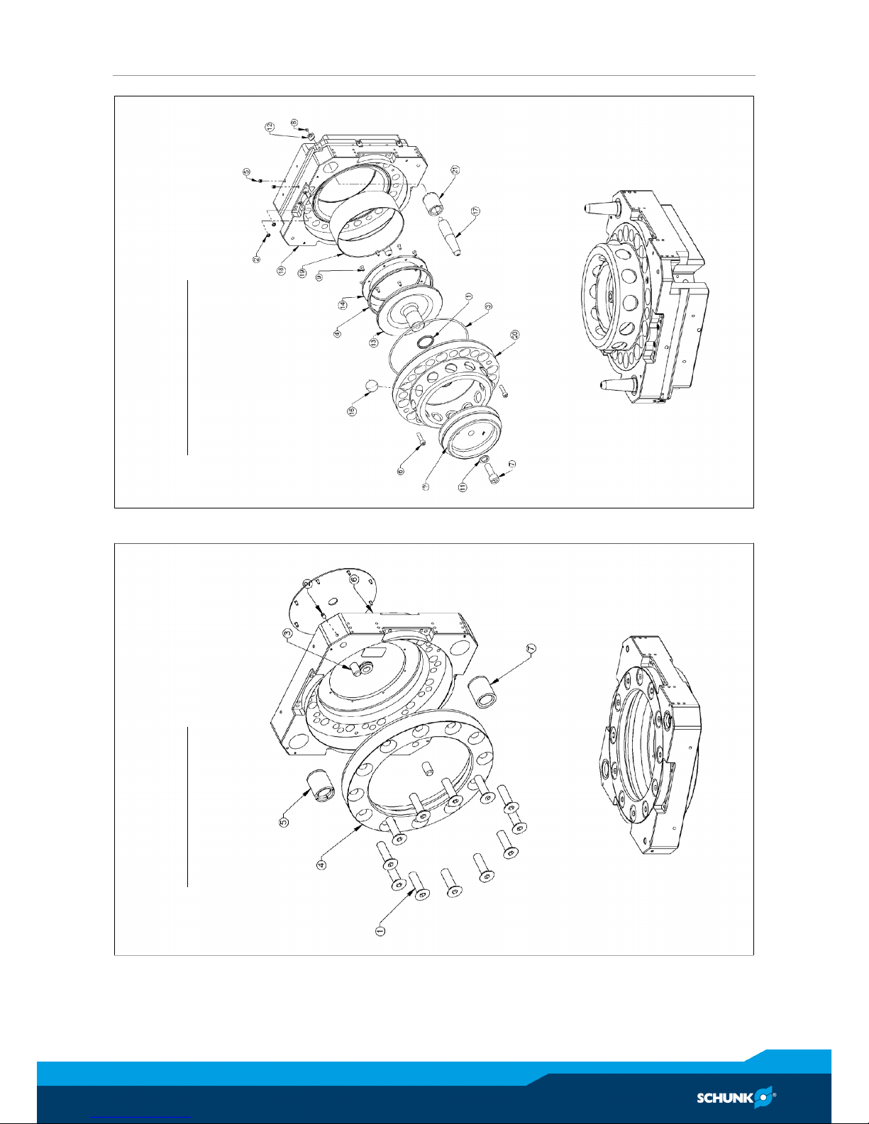
Maintenance and Care
02.00 | SWS-L | Assembly and operating manual | en | 0389037
57
SWK-L-510 Master Assembly
SWK-L 510
SWA-L-510 Tool Assembly
SWA-L 510
Page 58
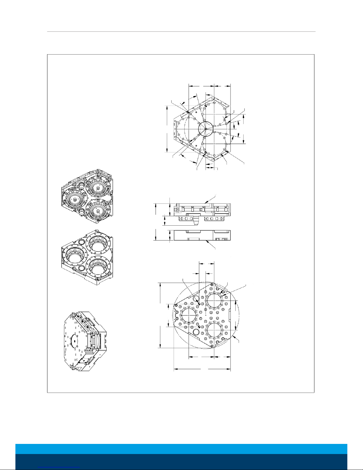
Maintenance and Care
58
02.00 | SWS-L | Assembly and operating manual | en | 0389037
8.4.4 SWS-L-1210
(4) C'Bored 10.4 Dp.
From Far Side
For M10 SHCS
Customer Interface
137.2
30°
87.6
15°
(2) R113.5
(2) C'Bored 10.4 Dp.
From Far Side
For M10 SHCS
Customer Interface
250
158.4
28°
14°
(10) C'Bored 10.6 Dp.
From Far Side
For M10 SHCS
30° Typ. Spacing
Pattern (3) Places
Customer Interface
B.C. Ø125
(3) Places
Customer Interface
45.7
15°
(2) Ø12(Slip Fit)
13.5 Dp.
Customer Interface
30°
(4)R115.5
(A)
68.1
SWK-L
[4.81"]
122.2
Coupled
54.1
SWA-L
(B)
Slide View
(Uncoupled)
SWK-L Side
(projection only)
81.3
(35.6)
B.C Ø91
(3) Places
Customer Interface
(12) C'Bored 41.9 Dp.
From Far Side
For M10 SHCS
Equally Spaced
Pattern (3) Places
Customer Interface
15.8.4
SWA-L Side
(projection only)
Ø359
SWK-L & SWA-L
87.6
137.2
305
SWK-L & SWA-L
123.2
351
SWK-L & SWA-L
Part Numbers:
(A) SWK-L: 9121-1210AM-0-0-0-0-0-0
(B) SWA-L: 9121-1210AT-0-0-0-0-0-0
Flat B
Flat C
Flat D
Flat A
Flat F
Flat E
Flat D
Flat A
Flat C
Flat B
Notes:
1. Tool Changer consists of three locking mechanisms and share a common lock
and unlock air supply.
2. Tool Changer capable of detecting 'Lock' and 'Unlock' for each locking mechanism.
3. Tool Changer capable of detecting 'RTL' (Ready-to-Lock) using (3) proximity sensors.
SWS-L 1210
Page 59
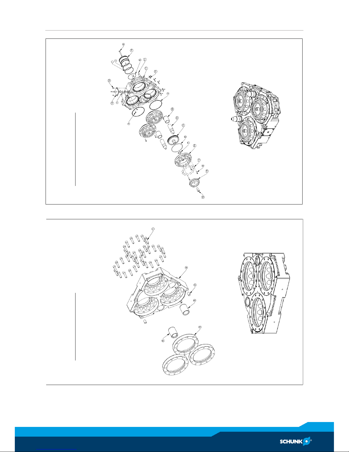
Maintenance and Care
02.00 | SWS-L | Assembly and operating manual | en | 0389037
59
SWK-L-1210 Master Assembly
SWK-L 1210
SWA-L-1210 Tool Assembly
SWA-L 1210
Page 60

Translation of original declaration of incorporation
60
02.00 | SWS-L | Assembly and operating manual | en | 0389037
9 Translation of original declaration of incorporation
in terms of the Directive 2006/42/EG, Annex II, Part 1.B of the European Parliament and of
the Council on machinery.
Manufacturer/
Distributor
SCHUNK GmbH & Co. KG Spann- und Greiftechnik
Bahnhofstr. 106 – 134
D-74348 Lauffen/Neckar
We hereby declare that on the date of the declaration the following partly completed machine complied with all basic safety and health regulations found in the directive 2006/42/
EC of the European Parliament and of the Council on machinery. The declaration is
rendered invalid if modifications are made to the product.
Product designation:
Heavy Load Change System / SWS-L
The partly completed machine may not be put into operation until conformity of the machine into which the partly completed machine is to be installed with the provisions of the
Machinery Directive (2006/42/EC) is confirmed.
The manufacturer agrees to forward on demand the relevant technical documentation for
the partly completed machinery in electronic form to national authorities.
The relevant technical documentation according to AnnexVII, Part B, belonging to the
partly completed machinery, has been created.
Person authorized to compile the technical documentation:
Robert Leuthner, Address: see manufacturer's address
Lauffen/Neckar, November 2018 p.p. Ralf Winkler,
Manager for development
of gripping system components
Page 61
Translation of original declaration of incorporation
02.00 | SWS-L | Assembly and operating manual | en | 0389037
61
9.1 Annex to Declaration of Incorporation
according 2006/42/EG, Annex II, No. 1 B
1.Description of the essential health and safety requirements pursuant to 2006/42/EC, Annex I that are applicable and that have been fulfilled with:
Product designation Heavy Load Change System
Type designation SWS-L
To be provided by the System Integrator for the overall machine ⇓
Fulfilled for the scope of the partly completed machine ⇓
Not relevant ⇓
1.1 Essential Requirements
1.1.1 Definitions X
1.1.2 Principles of safety integration X
1.1.3 Materials and products X
1.1.4 Lighting X
1.1.5 Design of machinery to facilitate its handling X
1.1.6 Ergonomics X
1.1.7 Operating positions X
1.1.8 Seating X
1.2 Control Systems
1.2.1 Safety and reliability of control systems X
1.2.2 Control devices X
1.2.3 Starting X
1.2.4 Stopping X
1.2.4.1 Normal stop X
1.2.4.2 Operational stop X
1.2.4.3 Emergency stop X
1.2.4.4 Assembly of machinery X
1.2.5 Selection of control or operating modes X
1.2.6 Failure of the power supply X
1.3 Protection against mechanical hazards
1.3.1 Risk of loss of stability X
1.3.2 Risk of break-up during operation X
1.3.3 Risks due to falling or ejected objects X
1.3.4 Risks due to surfaces, edges or angles X
1.3.5 Risks related to combined machinery X
1.3.6 Risks related to variations in operating conditions X
Page 62
Translation of original declaration of incorporation
62
02.00 | SWS-L | Assembly and operating manual | en | 0389037
1.3 Protection against mechanical hazards
1.3.7 Risks related to moving parts X
1.3.8 Choice of protection against risks arising from moving parts X
1.3.8.1 Moving transmission parts X
1.3.8.2 Moving parts involved in the process X
1.3.9 Risks of uncontrolled movements X
1.4 Required characteristics of guards and protective devices
1.4.1 General requirements X
1.4.2 Special requirements for guards X
1.4.2.1 Fixed guards X
1.4.2.2 Interlocking movable guards X
1.4.2.3 Adjustable guards restricting access X
1.4.3 Special requirements for protective devices X
1.5 Risks due to other hazards
1.5.1 Electricity supply X
1.5.2 Static electricity X
1.5.3 Energy supply other than electricity X
1.5.4 Errors of fitting X
1.5.5 Extreme temperatures X
1.5.6 Fire X
1.5.7 Explosion X
1.5.8 Noise X
1.5.9 Vibrations X
1.5.10 Radiation X
1.5.11 External radiation X
1.5.12 Laser radiation X
1.5.13 Emissions of hazardous materials and substances X
1.5.14 Risk of being trapped in a machine X
1.5.15 Risk of slipping, tripping or falling X
1.5.16 Lightning X
1.6 Maintenance
1.6.1 Machinery maintenance X
1.6.2 Access to operating positions and servicing points X
1.6.3 Isolation of energy sources X
1.6.4 Operator intervention X
1.6.5 Cleaning of internal parts X
Page 63
Translation of original declaration of incorporation
02.00 | SWS-L | Assembly and operating manual | en | 0389037
63
1.7 Information
1.7.1 Information and warnings on the machinery X
1.7.1.1 Information and information devices X
1.7.1.2 Warning devices X
1.7.2 Warning of residual risks X
1.7.3 Marking of machinery X
1.7.4 Instructions X
1.7.4.1 General principles for the drafting of instructions X
1.7.4.2 Contents of the instructions X
1.7.4.3 Sales literature X
The classification from Annex 1 is to be supplemented from here forward.
2 Supplementary essential health and safety requirements for certain
categories of machinery
X
2.1 Foodstuffs machinery and machinery for cosmetics or pharmaceutical
products
X
2.2 Portable hand-held and/or guided machinery X
2.2.1 Portable fixing and other impact machinery X
2.3 Machinery for working wood and material with similar physical characteristics
X
3 Supplementary essential health and safety requirements to offset haz-
ards due to the mobility of machinery
X
4 Supplementary essential health and safety requirements to offset haz-
ards due to lifting operations
X
5 Supplementary essential health and safety requirements for machinery
intended for underground work
X
6 Supplementary essential health and safety requirements for machinery
presenting particular hazards due to the lifting of persons
X
Page 64

64
02.00 | SWS-L | Assembly and operating manual | en | 0389037
 Loading...