

SCHUNK ROTA TPS 125-26 K, ROTA TPS 160-38 K, ROTA TPS 160-38 Z, ROTA TPS 200-52 K, ROTA TPS 200-52 Z Assembly And Operating Manual
...
Translation of the original manual
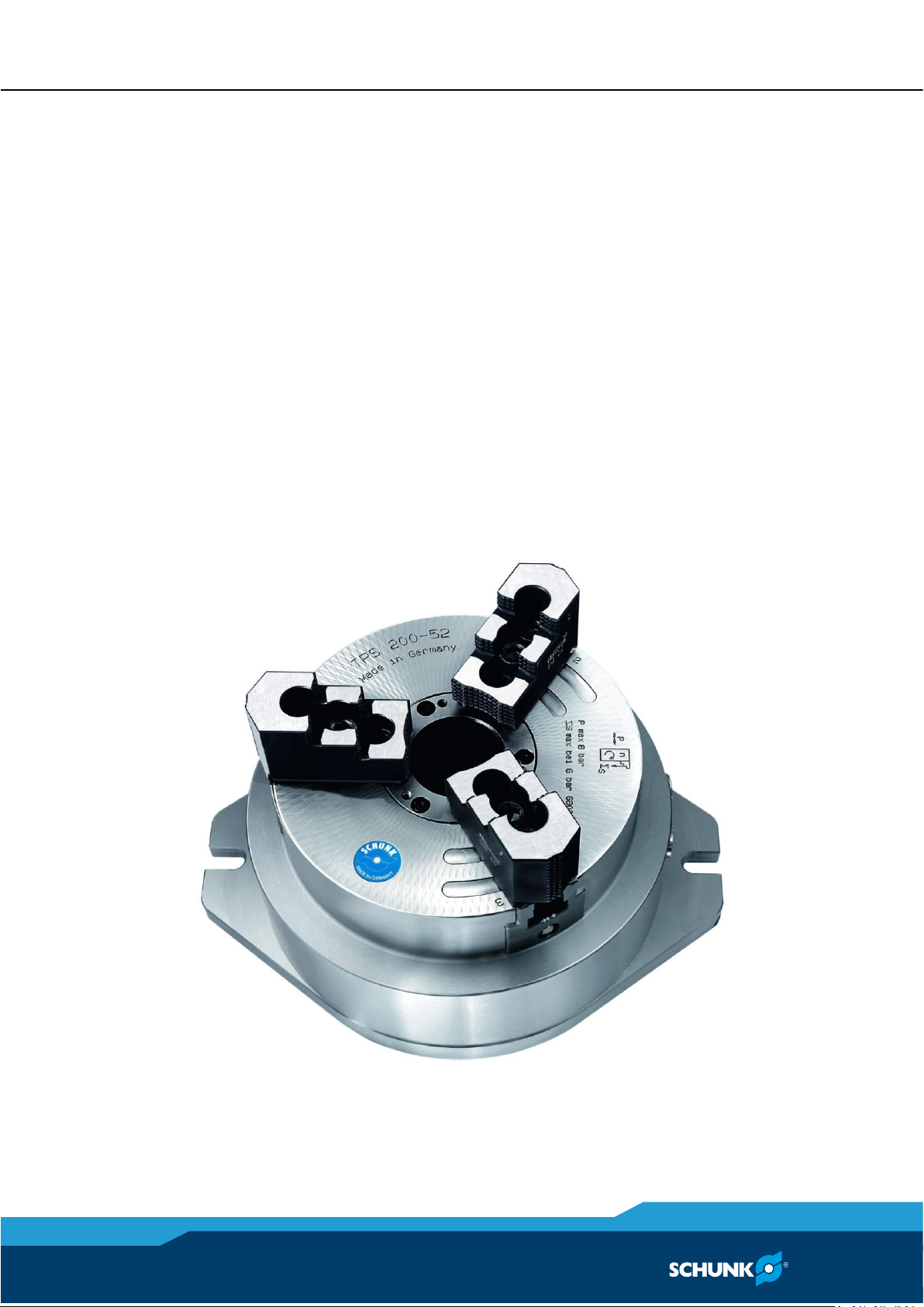
Stationary 3-Jaw-Power-Chuck
ROTA TPS-K, ROTA TPS-Z
Assembly and operating Manual
Superior Clamping and Gripping

Imprint
2
03.00|ROTA TPS-K, ROTA TPS-Z |en
Imprint
Copyright:
This manual is protected by copyright. The author is SCHUNK GmbH & Co. KG. All rights
reserved. Any reproduction, processing, distribution (making available to third parties),
translation or other usage - even excerpts - of the manual is especially prohibited and
requires our written approval.
Technical changes:
We reserve the right to make alterations for the purpose of technical improvement.
Document number: 0889145
Version: 03.00 |19/09/2018|en
© H.-D. SCHUNK GmbH & Co.
All rights reserved.
Dear Customer,
thank you for trusting our products and our family-owned company, the leading
technology supplier of robots and production machines.
Our team is always available to answer any questions on this product and other solutions.
Ask us questions and challenge us. We will find a solution!
Best regards,
Your SCHUNK team
H.-D. SCHUNK GmbH & Co.
Spanntechnik KG
Lothringer Str. 23
D-88512 Mengen
Tel. +49–7572-7614-0
Fax +49-7572-7614-1099
info@de.schunk.com
schunk.com

Table of contents
03.00|ROTA TPS-K, ROTA TPS-Z |en
3
Table of contents
1
General .................................................................................................................... 5
1.1
About this manual .................................................................................................... 5
1.1.1
Presentation of Warning Labels .................................................................... 5
1.1.2
Applicable documents ................................................................................... 6
1.1.3
Sizes ............................................................................................................... 6
1.2
Warranty ................................................................................................................... 6
1.3
Scope of delivery ...................................................................................................... 6
1.4
Accessories ............................................................................................................... 6
2
Basic safety notes .................................................................................................... 7
2.1
Intended use ............................................................................................................. 7
2.2
Not intended use ...................................................................................................... 7
2.3
Constructional changes ............................................................................................ 7
2.4
Spare parts ................................................................................................................ 8
2.5
Chuck jaws ................................................................................................................ 8
2.6
Environmental and operating conditions ................................................................. 8
2.7
Personnel qualification ............................................................................................. 9
2.8
Personal protective equipment .............................................................................. 10
2.9
Notes on safe operation ......................................................................................... 10
2.10
Transport ................................................................................................................ 10
2.11
Malfunctions ........................................................................................................... 11
2.12
Disposal ................................................................................................................... 11
2.13
Fundamental dangers ............................................................................................. 11
2.13.1
Protection during handling and assembly .................................................. 12
2.13.2
Protection during commissioning and operation ....................................... 12
2.13.3
Protection against dangerous movements ................................................. 12
2.13.4
Notes on particular risks ............................................................................. 13
3
Technical data ......................................................................................................... 16
4
Torques per screw ................................................................................................... 17
5
Functional testing .................................................................................................... 17
6
Maintenance ........................................................................................................... 18
6.1
Pre-assembly measures .......................................................................................... 18
6.2
Connection of the stationary 3-Jaw-Power-Chuck................................................. 18
6.3
Assembly of the TPS on the machine table ............................................................ 19
7
Commissioning and maintenance ............................................................................ 20
7.1
Initial operation ...................................................................................................... 20

Table of contents
4
03.00|ROTA TPS-K, ROTA TPS-Z |en
7.2
Hardened Reversible Jaws and Soft Top Jaws........................................................ 20
7.3
Maintenance and Lubrication ................................................................................ 21
7.4
Control of thightness .............................................................................................. 21
7.5
Disassembly and assembly ..................................................................................... 22
7.5.1
Disassembly and cleaning ........................................................................... 22
7.5.2
Assembly ..................................................................................................... 23
8
Trouble shooting ..................................................................................................... 25
8.1
The chuck jaws do not move .................................................................................. 25
8.2
The Clamping System does not move the full stroke? ........................................... 25
8.3
Clamping force getting weaker .............................................................................. 25
8.4
Clamping system movement jerky ......................................................................... 25
9
Spare parts .............................................................................................................. 26
10
Drawing................................................................................................................... 27
11
Translation of original declaration of incorporation ................................................. 28

General
03.00|ROTA TPS-K, ROTA TPS-Z |en
5
General
About this manual
This manual contains important information for a safe and
appropriate use of the product.
This manual is an integral part of the product and must be kept
accessible for the personnel at all times.
Before starting work, the personnel must have read and
understood this operating manual. Prerequisite for safe working is
the observance of all safety instructions in this manual.
Illustrations in this manual are provided for basic understanding
and may differ from the actual product design.
In addition to these instructions, the documents listed under
( 1.1.2, Page 6) are applicable.
Presentation of Warning Labels
To make risks clear, the following signal words and symbols are
used for safety notes.
DANGER
Danger for persons!
Non-observance will inevitably cause irreversible injury or death.
WARNING
Dangers for persons!
Non-observance can lead to irreversible injury and even death.
CAUTION
Dangers for persons!
Non-observance can cause minor injuries.
NOTICE
Material damage!
Information about avoiding material damage.
1
1.1
1.1.1

General
6
03.00|ROTA TPS-K, ROTA TPS-Z |en
Applicable documents
• General terms of business*
• Catalog data sheet of the purchased product *
The documents marked with an asterisk (*) can be downloaded on
our homepage schunk.com
Sizes
This operating manual applies to the following sizes:
• ROTA TPS 125-26; 160-38; 200-52; 250-68; 315-90; 315-105
Warranty
The warranty period is 24 months after delivery date from factory
or 300 000 cycles*, if it is used as intended, under the following
conditions:
• Observe the applicable documents ( 1.1.2, Page 6)
• Observe the ambient conditions and operating conditions,
( 2.6, Page 8)
• Observe the specified maintenance and lubrication intervals,
( 7, Page 20)
Parts touching the workpiece and wear parts are not included in
the warranty.
* A cycle consists of a complete clamping process
("Open" and "Close").
Scope of delivery
stationary 3-jaw chuck ROTA TPS (without top jaws)
2
Elbow unions
2
Straight fittings
6
T-nuts
6
Cylindrical screws for top jaws
1
Assembly tool
only for TPS-Z:
6
Studs
6
Hexagon nuts
Accessories
(see catalog or data sheets when ordering separately)
• Top jaws
(also available from SCHUNK in a workpiece-specific design)
• Gripping force maintenance device with pressure maintenance
valve
1.1.2
1.1.3
1.2
1.3
1.4

Basic safety notes
03.00|ROTA TPS-K, ROTA TPS-Z |en
7
Basic safety notes
Intended use
This product is intended for clamping workpieces on machine tools
and other suitable technical devices.
• The product may only be used within the scope of its technical
data, ( 3, Page 16).
• The product is intended for industrial and industry-oriented
use.
• Appropriate use of the product includes compliance with all
instructions in this manual.
Not intended use
The power chuck for stationary use/application is not being used
as intended if, for example:
• It is used as a lathe chuck.
• It is used as a press, a punch, a chuck, a load-handling device or
as lifting equipment.
• It is used in working environments that are not permissible.
• Workpieces are not clamped properly, paying particular
attention to the clamping forces specified by the manufacturer.
• People work on machines or technical equipment that do not
comply with the EC Machinery Directive 2006/42/EC,
disregarding the applicable safety regulations.
• The technical data specified by the manufacturer for using the
chuck are exceeded.
Constructional changes
Implementation of structural changes
By conversions, changes, and reworking, e.g. additional threads,
holes, or safety devices can impair the functioning or safety of the
product or damage it.
• Structural changes should only be made with the written
approval of SCHUNK.
2
2.1
2.2
2.3

Basic safety notes
8
03.00|ROTA TPS-K, ROTA TPS-Z |en
Spare parts
Use of unauthorized spare parts
Using unauthorized spare parts can endanger personnel and
damage the product or cause it to malfunction.
• Use only original spare parts or spares authorized by SCHUNK.
Chuck jaws
Requirements of the chuck jaws
Stored energy can make the product unsafe and risk the danger of
serious injuries and considerable material damage.
• Only replace chuck jaws if no residual energy can be released.
• Do not use welded jaws.
• The chuck jaws should be designed to be as light and as low as
possible. The clamping point must be as close as possible to the
chuck face (clamping points at a greater distance lead to
greater surface pressure in the jaw guidance and can
significantly reduce the clamping force).
• Screw the jaw mounting bolts into the bore holes furthest
apart.
• After a collision, the lathe chuck and the chuck jaws must be
subjected to a crack test before being used again. Damaged
parts must be replaced with original SCHUNK spare parts.
• Replace the chuck jaw mounting bolts if there are signs of wear
or damage. Only use bolts with a quality of 12.9.
Environmental and operating conditions
Required ambient conditions and operating conditions
Incorrect ambient and operating conditions can make the product
unsafe, leading to the risk of serious injuries, considerable material
damage and/or a significant reduction to the product's life span.
• Make sure that the product is used only in the context of its
defined application parameters, ( 3, Page 16).
• Make sure that the product is a sufficient size for the
application.
• Only use high-quality cooling emulsions with anti-corrosive
additives during processing.
• Lubricating intervals must be adhered to ( 7.3, Page 21).
2.4
2.5
2.6

Basic safety notes
03.00|ROTA TPS-K, ROTA TPS-Z |en
9
Personnel qualification
Inadequate qualifications of the personnel
If the personnel working with the product is not sufficiently
qualified, the result may be serious injuries and significant
property damage.
• All work may only be performed by qualified personnel.
• Before working with the product, the personnel must have read
and understood the complete assembly and operating manual.
• Observe the national safety regulations and rules and general
safety instructions.
The following personal qualifications are necessary for the various
activities related to the product:
Due to their technical training, knowledge and experience, trained
electricians are able to work on electrical systems, recognize and
avoid possible dangers and know the relevant standards and
regulations.
Due to its technical training, knowledge and experience, qualified
personnel is able to perform the delegated tasks, recognize and
avoid possible dangers and knows the relevant standards and
regulations.
Instructed persons were instructed by the operator about the
delegated tasks and possible dangers due to improper behaviour.
Due to its technical training, knowledge and experience, service
personnel of the manufacturer is able to perform the delegated
tasks and to recognize and avoid possible dangers.
2.7
Trained electrician
Qualified personnel
Instructed person
Service personnel of
the manufacturer

Basic safety notes
10
03.00|ROTA TPS-K, ROTA TPS-Z |en
Personal protective equipment
Use of personal protective equipment
Personal protective equipment serves to protect staff against
danger which may interfere with their health or safety at work.
• When working on and with the product, observe the
occupational health and safety regulations and wear the
required personal protective equipment.
• Observe the valid safety and accident prevention regulations.
• Wear protective gloves to guard against sharp edges and
corners or rough surfaces.
• Wear heat-resistant protective gloves when handling hot
surfaces.
• Wear protective gloves and safety goggles when handling
hazardous substances.
• Wear close-fitting protective clothing and also wear long hair in
a hairnet when dealing with moving components.
Notes on safe operation
Incorrect handling of the personnel
Incorrect handling and assembly may impair the product's safety
and cause serious injuries and considerable material damage.
• Avoid any manner of working that may interfere with the
function and operational safety of the product.
• Use the product as intended.
• Observe the safety notes and assembly instructions.
• Do not expose the product to any corrosive media. This does
not apply to products that are designed for special
environments.
• Eliminate any malfunction immediately.
• Observe the care and maintenance instructions.
• Observe the current safety, accident prevention and
environmental protection regulations regarding the product's
application field.
Transport
Handling during transport
Incorrect handling during transport may impair the product's
safety and cause serious injuries and considerable material
damage.
2.8
2.9
2.10

Basic safety notes
03.00|ROTA TPS-K, ROTA TPS-Z |en
11
• When handling heavy weights, use lifting equipment to lift the
product and transport it by appropriate means.
• Secure the product against falling during transportation and
handling.
• Stand clear of suspended loads.
Malfunctions
Behavior in case of malfunctions
• Immediately remove the product from operation and report
the malfunction to the responsible departments/persons.
• Order appropriately trained personnel to rectify the
malfunction.
• Do not recommission the product until the malfunction has
been rectified.
• Test the product after a malfunction to establish whether it still
functions properly and no increased risks have arisen.
Disposal
Handling of disposal
The incorrect handling of disposal may impair the product's safety
and cause serious injuries as well as considerable material and
environmental harm.
• Follow local regulations on dispatching product components for
recycling or proper disposal.
Fundamental dangers
General
• Observe safety distances.
• Never deactivate safety devices.
• Before commissioning the product, take appropriate protective
measures to secure the danger zone.
• Disconnect power sources before installation, modification,
maintenance, or calibration. Ensure that no residual energy
remains in the system.
• If the energy supply is connected, do not move any parts by
hand.
• Do not reach into the open mechanism or movement area of
the product during operation.
2.11
2.12
2.13

Basic safety notes
12
03.00|ROTA TPS-K, ROTA TPS-Z |en
Protection during handling and assembly
Incorrect handling and assembly
Incorrect handling and assembly may impair the product's safety
and cause serious injuries and considerable material damage.
• Have all work carried out by appropriately qualified personnel.
• For all work, secure the product against accidental operation.
• Observe the relevant accident prevention rules.
• Use suitable assembly and transport equipment and take
precautions to prevent jamming and crushing.
Incorrect lifting of loads
Falling loads may cause serious injuries and even death.
• Stand clear of suspended loads and do not step into their
swiveling range.
• Never move loads without supervision.
• Do not leave suspended loads unattended.
Protection during commissioning and operation
Falling or violently ejected components
Falling and violently ejected components can cause serious injuries
and even death.
• Take appropriate protective measures to secure the danger
zone.
• Never step into the danger zone during operation.
Protection against dangerous movements
Unexpected movements
Residual energy in the system may cause serious injuries while
working with the product.
• Switch off the energy supply, ensure that no residual energy
remains and secure against inadvertent reactivation.
• Never rely solely on the response of the monitoring function to
avert danger. Until the installed monitors become effective, it
must be assumed that the drive movement is faulty, with its
action being dependent on the control unit and the current
operating condition of the drive. Perform maintenance work,
modifications, and attachments outside the danger zone
defined by the movement range.
• To avoid accidents and/or material damage, human access to
the movement range of the machine must be restricted.
2.13.1
2.13.2
2.13.3
Basic safety notes
03.00|ROTA TPS-K, ROTA TPS-Z |en
13
Limit/prevent accidental access for people in this area due
through technical safety measures. The protective cover and
protective fence must be rigid enough to withstand the
maximum possible movement energy. EMERGENCY STOP
switches must be easily and quickly accessible. Before starting
up the machine or automated system, check that the
EMERGENCY STOP system is working. Prevent operation of the
machine if this protective equipment does not function
correctly.
Notes on particular risks
DANGER
Risk of fatal injury to operating personnel due to the workpiece
falling down or being flung out in the event of a power failure
In the event of a power failure, the lathe chuck's clamping force
may fail immediately and the workpiece may be released in an
uncontrolled manner. This poses a risk of death or injury to the
operating personnel and can result in serious damage to the
automated system.
• The machine manufacturer and the operator of the machine
must carry out and document a hazard assessment and risk
analysis to ensure that suitable measures are taken to
maintain the lathe chuck's clamping force until the machine
comes to a standstill and the workpiece can be secured (e.g.
using a crane or suitable lifting equipment).
• The machines and equipment must fulfill the minimum
requirements of the EC Machinery Directive; specifically, they
must have effective technical measures to protect against
potential mechanical hazards.
2.13.4

Basic safety notes
14
03.00|ROTA TPS-K, ROTA TPS-Z |en
DANGER
Possible risk of fatal injury to operating personnel if a jaw
breaks or if the lathe chuck fails because the technical data have
been exceeded and a workpiece is released or parts fly off
• The technical data specified by the manufacturer for using the
lathe chuck must never be exceeded.
• The lathe chuck may only be used on machines and facilities
that fulfill the minimum requirements of the EC Machinery
Directive; specifically, they must have effective technical
measures to protect against possible mechanical hazards.
WARNING
Risk of injury due to dropping the chuck during transport,
installation or removal.
• Take special care in the danger zone when transporting,
installing or removing the chuck.
• Note the relevant load securing regulations for working safely
with cranes, ground conveyors, lifting gear and load-handling
equipment.
CAUTION
Danger of slipping and falling in case of dirty environment
where the chuck is used (e.g. by cooling lubricants or oil).
• Ensure that the working environment is clean before starting
assembly and installation work.
• Wear suitable safety shoes.
• Follow the safety and accident-prevention regulations when
operating the chuck, especially when working with machine
tools and other technical equipment.

Basic safety notes
03.00|ROTA TPS-K, ROTA TPS-Z |en
15
CAUTION
Danger of limbs being crushed by opening and closing of the
chuck jaws during manual loading and unloading or when
replacing moving parts.
• Do not reach between the jaws.
• Wear safety gloves.
• Observe the safety and accident prevention regulations during
operation of the chuck, especially in connection with
machining centers and other technical equipment.
CAUTION
Risk of burns due to workpieces with high temperatures.
• Wear protective gloves when removing the workpieces.
• Automatic loading is preferred.
CAUTION
Risk of damage due to incorrect choice of clamping position for
chuck jaws on workpiece.
If an incorrect clamping position is chosen for the chuck jaws on
workpiece, the base and top jaws may become damaged.
• The T-nuts for connecting the top jaws to the base jaws must
not protrude beyond the base jaws in the radial direction.
• The diameter of the workpiece may not be bigger than the
chuck diameter.
CAUTION
Danger from noise generation
Physical and mental stress by noise generation during the
working process.
• Wear hearing protection.

Technical data
16
03.00|ROTA TPS-K, ROTA TPS-Z |en
Technical data
Actuation pressure
6 bar
Pressure medium
Compressed air, compressed air quality according to
ISO 8573-1:7 4 4
Operating temperature
+ 5°C to + 60°C
Noise emission
≤ 70 dB (A)
Installation position
Any
ROTA TPS
125-26 / K
125-26 / Z
160-38 / K
160-38 / Z
ID no.
0816127
0816126
0816137
0816136
Stroke per jaw [mm]
3 3 4.2
4.2
Max. clamping force* [kN]
22
22
39
39
Air consumption per double stroke
[cm3]
2200
2200
4800
4800
Closing/opening time at 6 bar [s]
0.35
0.35
0.39
0.39
Weight [kg]
12
12
23
23
Max. jaw stroke [mm]
40
40
40
40
ROTA TPS
200-52 / K
200-52 / Z
250-68 / K
250-68 / Z
ID no.
0816147
0816146
0816157
0816156
Stroke per jaw [mm]
4.2
4.2 5 5
Max. clamping force* [kN]
68
68
105
105
Air consumption per double stroke
[cm3]
7800
7800
13200
13200
Closing/opening time at 6 bar [s]
0.85
0.85
0.89
0.89
Weight [kg]
34
34
60
60
Max. jaw stroke [mm]
54
54
70
70
ROTA TPS
315-90 / K
315-90 / Z
315-105 / K
315-105 / Z
ID no.
0816167
0816166
88000779
88000785
Stroke per jaw [mm]
5 5 5 5 Max. clamping force* [kN]
140
140
80
80
Air consumption per double stroke
[cm3]
16400
16400
10800
10800
Closing/opening time at 6 bar [s]
1.2
1.2
1.5
1.5
Weight [kg]
82
82
72
72
Max. jaw stroke [mm]
76
76
70
70
* Clamping force is the arithmetic sum of the individual forces
occurring at the chuck jaws at a distance of "H" at 6 bar
3

Functional testing
03.00|ROTA TPS-K, ROTA TPS-Z |en
17
Torques per screw
Tightening torques for mounting screws used to clamp the chuck
on lathes or other suitable technical equipment (screw quality
10.9)
Screw size
M6
M8
M10
M12
M14
M16
M18
M20
M22
M24
M27
M30
Admissible torque
MA (Nm)
13
28
50
88
120
160
200
290
400
500
1050
1500
Tightening torques for mounting screws used to attach top jaws
onto the chuck (screw quality 12.9)
Screw size
M6
M8
M10
M12
M14
M16
M20
M24
Max. admissible torque MA (Nm)
16
30
50
70
130
150
220
450
Functional testing
Functional test
After installation of the chuck, its function must be checked prior
to start-up. Make sure there are no leaks in the line system.
Two important points are:
• Clamping force! At max. actuating force/pressure, the clamping
force specified for the chuck must be reached.
• Stroke control The stroke of the clamping piston must have a
margin of safety at the front and back end positions. The
machine tool must not start up until the clamping piston has
passed through the safety margin Only limit switches that meet
the requirements for safety limit switches specified in DIN EN
60204-1 may be used to monitor the clamping path.
If the chuck jaws are changed, adjust the stroke control to the new
situation.
4
5

Maintenance
18
03.00|ROTA TPS-K, ROTA TPS-Z |en
Maintenance
NOTICE
The power supply must be switched off during assembly and
connection of the clamping system.
Pre-assembly measures
Carefully lift the product (e.g. using suitable lifting gear) from the
packaging.
CAUTION
Danger of injury due to sharp edges and rough or slippery
surfaces
Use personal protective gear, especially safety gloves.
Check the delivery for completeness and for transport damage.
Connection of the stationary 3-Jaw-Power-Chuck
ROTA TPS has 2 air connections for OPEN and CLOSED.
1
CLOSED
2
OPEN
6
6.1
6.2

Maintenance
03.00|ROTA TPS-K, ROTA TPS-Z |en
19
Thread for air connections
ROTA TPS 125
G1/8"
ROTA TPS 160
G1/4"
ROTA TPS 200
G1/4"
ROTA TPS 250
G1/4"
ROTA TPS 315
G1/4"
NOTICE
Always make sure the connections are tight, and protect the
pneumatic hoses from hot chips and falling parts by using a
suitable metal hose.
NOTICE
When actuating the clamping device (clamping or releasing), a
short pause for ventilation must be maintained between each
shifting operation. This ventilation pause must be at least 0.5
seconds, depending on the length of the hose. A 4/3 or 5/3-way
valve is recommended for this purpose (center position
depressurized).
Assembly of the TPS on the machine table
Adjustment grooves are provided on both locating surfaces of all
stationary, pneumatically operated power clamping units of type
ROTA TPS-K, which enable mounting on the work table by means
of T-nuts. The T-nuts must be made or ordered according to the
width of the groove of the table.
Corresponding devices must be made by the customer for types
ROTA TPS-Z which ensure secure mounting and enable adjustment
of the power chucks.
6.3

Commissioning and maintenance
20
03.00|ROTA TPS-K, ROTA TPS-Z |en
Commissioning and maintenance
Initial operation
Check whether the jaw guides and the piston of the ROTA TPS
power chuck are sufficiently lubricated at the lubricating nipples
embedded in the base jaws.
If required, lubricate the chuck with the base jaws retracted, by
using LINOMAX special grease from SCHUNK.
NOTICE
An insufficiently lubricated chuck will result in a significantly
reduced clamping force.
Turning, facing or skimming of the front-end power chuck is not
permitted.
Drilling of the chuck on the front face side may be performed only
after consulting the SCHUNK technical sales department.
Hardened Reversible Jaws and Soft Top Jaws
Fine serration of the base and top jaws is 1/16" x 90°. The
adjusting stroke from tooth to tooth is approximately 1.6 mm.
NOTICE
It must be ensured that the top jaws are fixed on the fine
serration in such a way that a maximum of 2/3 the jaw stroke is
extended for clamping.
Hardened reversible jaws should only be used in sets in
accordance with the packaging, as they are manufactured on the
device in sets. 1 set of hardened reversible jaws is normally
ordered for a power chuck.
When installing and removing the reversible jaws numbered 1 - 3,
make sure that the individual jaws are installed/removed on/from
the base jaws with the same designation to ensure a high level of
accuracy of the clamping center.
The fine serration of the base jaws and top jaws should always be
cleaned when the top jaws are adjusted, because otherwise the
true running accuracy will be reduced.
The screws of the hardened reversible jaws and soft top jaws must
be tightened with the specified torque.
7
7.1
7.2

Commissioning and maintenance
03.00|ROTA TPS-K, ROTA TPS-Z |en
21
Maintenance and Lubrication
• A maintenance unit consisting of filter, water separator and
oiler should be connected upstream of the power chuck. The
air enriched with oil supplies all sliding parts of the cylinder
chamber with an oil film. Check the oil level of the oil tank on a
daily basis and refill if necessary. If the oil consumption is too
low, i.e. if the oil level does not visibly drop over a period of 2
to 3 days, the oil adjustment screw must be opened slightly.
Depending on the accumulation of condensation, the
condensation drain screw must be opened occasionally.
The uniform clamping force, accuracy, and life span of a chuck
depend greatly on regular cleaning and sufficient lubrication. Rust,
scale, casting dust, and chips produce friction and reduce motion.
• The chuck must be lubricated with SCHUNK LINOMAX special
grease at the base jaw lubrication nipples by means of a grease
gun after every 20 – 30 operating hours. The chuck should be
actuated two to three times here without a workpiece to
achieve optimum grease distribution by means of the
completely extended jaw stroke.
• The fine serration of the base jaws and top jaws should always
be cleaned when the top jaws are adjusted, because otherwise
the true running accuracy will be reduced.
Even though there is optimum sealing provided by the hardened
guide bushing in the through-hole and by the closed base jaws,
foreign matter, such as dust, scale, casting dust, and fine chips can
penetrate into the chuck. In addition, the coolant also washes
away the lubricant of the chuck.
• The chuck must be completely disassembled, cleaned and
relubricated from time to time. When doing this, replace the
sealing rings if necessary. ( 7.5, Page 22)
The time until complete maintenance depends on the presence
of dirt and the clamping frequency, so a generally applicable
rule cannot be provided.
Control of thightness
NOTE:
Temperature fluctuations must be avoided during the leak test.
The following components are required to check for leaks:
pressure gauge, shut-off valve and quick coupler.
The leak test should only be conducted when the chuck is in the
"CLOSED" position.
Leak test sequence:
7.3
7.4

Commissioning and maintenance
22
03.00|ROTA TPS-K, ROTA TPS-Z |en
1 Seal the "OPEN" air connection so it is air-tight.
2 Connect the components to the open "CLOSED" air connection
in the following order:
pressure gauge – shut-off valve – coupling – supply line.
3 Pressurize the clamping system with compressed air until the
pressure gauge displays 6 bar.
4 Disconnect the supply line.
5 Let the clamping system sit clamped for 24 hours.
6 After 24 hours, the clamping block is:
sealed – if the pressure gauge indicates a pressure of ≥ 5.5
bar.
leaking – if the pressure gauge indicates a pressure of < 5.5
bar.
If the clamping system is leaking, check the screws first (e.g. with
Metaflux leak detection spray).
Seal any leaking screws.
Once the screws are sealed, the seals must be checked and
replaced if necessary.
Disassembly and assembly
The item numbers specified for the corresponding individual
components relate to chapter drawings.( 10, Page 27)
Disassembly and cleaning
1 On the chuck mount (item 7) with O-ring (item 48, 52),
unscrew the hexagon socket screws (item 39) and screw 3 of
these screws into the threaded extraction holes to push off
the mount.
2 Loosen the radial set screw (item 34) in the fixing nut (item
40). The clamping by the copper bolt (item 33) slows down
and the nut can be loosened with the enclosed assembly tool
(item 80).
3 Screw three hexagon socket screws into the threaded holes of
the piston cover (item 6) and force the piston cover (item 6)
from the piston (item 3).
4 On the front side of the chuck, loosen the socket screws (item
36) of the sleeve (item 4) and pull out the sleeve (item 4)
7.5
7.5.1

Commissioning and maintenance
03.00|ROTA TPS-K, ROTA TPS-Z |en
23
toward the front by lightly knocking from the back side of the
chuck.
5 Remove the sealing disk (item 5) fastened by socket screws
(item 37) and take out the O-ring (item 43).
6 The piston (item 3) can be pulled out of the chuck body (item
1) and the base jaws (item 2) can be pulled out of the base jaw
guides inwardly through the piston bore hole of the chuck
body. The base jaws (item 2) as well as the base jaw guides in
the chuck body (item 1) and the hardened reversible jaws are
numbered 1, 2, and 3. This ensures the same position, and
thus the same true-running accuracy, is achieved during
assembly.
7 Degrease and clean all parts and check them for damage.
8 Check all O-rings for possible damage and wear, replace them
if necessary, grease with Renolit HLT 2 or a equivalent grease,
and carefully reinstall them.
9 Lubricate the cylinder chamber of the chuck with oil.
Jaw guides in the chuck body, base jaws and piston at the
wedge hooks are greased with SCHUNK LINOMAX special
grease.
Assembly
NOTE:
All parts of the ROTA TPS power chuck are smooth-running
components. Therefore, do not strike the chuck hard with a
hammer during assembly.
1 Insert the designated base jaws (item 2) into the
corresponding guides, let the piston with the O-ring (item 47)
engage in the splines of the base jaws (item 2) and insert the
piston up to the end of the stroke.
2 Insert the O-ring (item 51) and sealing disk (item 5) with O-ring
(item 50) and screw them securely and air-tight to the chuck
body by means of the hexagon socket screws (item 37).
3 ROTA TPS 160-38, ROTA TPS 200-52, ROTA TPS 250-68, ROTA
TP 315-90: Insert the piston cover with the O-ring (item 6, 53)
and use the enclosed assembly tool (item 80) to mount the
lock nut (item 40). Lock the nut radially with the copper bolt
(item 33) and setscrew (item 34).
ROTA TPS 125-26: Use the enclosed assembly tool (item 80) to
assemble the lock nut (item 40). Securing the nut with safety
cord (item 33).
7.5.2

Commissioning and maintenance
24
03.00|ROTA TPS-K, ROTA TPS-Z |en
ROTA TPS 315-105: Assemble screws (item 40) and tighten
alternately.
4 Put on the chuck mount with O-rings (item 48, 52) and fasten
it with hexagon socket screws (item 39).
5 Insert the guide bushing (item 4) from the front side of the
chuck and tightly fasten it with the screws (item 36).

Trouble shooting
03.00|ROTA TPS-K, ROTA TPS-Z |en
25
Trouble shooting
The chuck jaws do not move
Possible cause
Corrective action
Air supply interrupted
Connections mixed up.
Check compressed air lines.
Piston will not move:
- Compressed air is not oiled.
- Maintenance unit with oiler is too far from
the chuck.
- The seal in the cover is not properly
inserted.
Install maintenance unit with oiler.
Position the maintenance unit with oiler
closer to the chuck.
Check the seal in the cover and insert
correctly.
The Clamping System does not move the full stroke?
Possible cause
Corrective action
Chips or dirt between guide bushing and
base jaws.
Completely disassemble, clean and
relubricate the chuck. ( 7.5, Page 22)
Clamping force getting weaker
Possible cause
Corrective action
The clamping system is leaking:
- Connection and/or sealing screws leaking.
- Seals damaged.
- Steel guide rollers on sliding surfaces not
greased.
Seal any leaking screws.
Disassemble chuck and replace seals
. ( 7.5, Page 22)
Lubricate the chuck with SCHUNK LINO MAX
special grease at the base jaw lubrication
nipples by means of a grease gun.
Clamping system movement jerky
Possible cause
Corrective action
Steel guide rollers on sliding surfaces not
greased.
Lubricate the chuck with SCHUNK LINO MAX
special grease at the base jaw lubrication
nipples by means of a grease gun.
8
8.1
8.2
8.3
8.4

Spare parts
26
03.00|ROTA TPS-K, ROTA TPS-Z |en
Spare parts
When ordering spare parts, it is imperative to specify the type,
size and above all the serial no. of the chuck.
Seals, sealing elements, screw connections, springs, bearings,
screws and wiper bars plus parts coming into contact with the
workpiece are not covered by the warranty.
Item
Designation
1
Chuck body
2
Base jaw
3
Piston
4
Bushing
5
Sealing disk
6
Piston cover
7
Bracket plate/Z-mount
8
T-nut
17
Sealing plug
33
Copper bolts
Safety lanyard (TPS 125)
34
Set-screw, DIN EN ISO 34827
36
Screws, DIN EN ISO 7984
37
Screws, DIN EN ISO 4762
39
Screws, DIN EN ISO 4762
40
Locking nut
Screws (ROTA TP 315-105)
41
Funnel lubrication nipple
43
Stud DIN 938 8.8 (Z-version)
44
Hexagon nut DIN 934-10 (Z-version)
45
Swivel fitting
46
Straight screw connection
47
O-ring
48
O-ring
49
O-ring
50
O-ring
51
O-ring
52
O-ring
53
O-ring
65
Copper sealing ring DIN 7603
67
Fiber seal
80
Assembly tool
9

Drawing
03.00|ROTA TPS-K, ROTA TPS-Z |en
27
Drawing
10

Translation of original declaration of incorporation
28
03.00|ROTA TPS-K, ROTA TPS-Z |en
Translation of original declaration of incorporation
in terms of the Directive 2006/42/EG, Annex II, Part 1.B of the European Parliament and of
the Council on machinery.
Manufacturer/
Distributor
H.-D. SCHUNK GmbH & Co. Spanntechnik KG
Lothringer Str. 23
D-88512 Mengen
We hereby declare that the following product:
Product designation:
Stationary 3-jaw chuck ROTA TPS-K, ROTA TPS-Z
ID number
0816127, 0816126, 0816137, 0816136, 0816147, 0816146,
0816157, 0816156, 0816167, 0816166, 88000779, 88000785
meets the applicable basic requirements of the Machinery Directive (2006/42/EC).
The partly completed machine may not be put into operation until conformity of the
machine into which the partly completed machine is to be installed with the provisions of
the Machinery Directive (2006/42/EC) is confirmed.
Applied harmonized standards, especially:
EN ISO 12100:2010
Safety of machinery - General principles for design Risk assessment and risk reduction
DIN EN 1550
Machine-tools safety – Safety requirements for the design and
constructions of workholding chucks
DIN 55028
Machine-tools – holding fixtures for clamping devices
The manufacturer agrees to forward on demand the special technical documents for the
partly completed machine to state offices.
The special technical documents according to Annex VII, Part B, belonging to the partly
completed machine have been created.
Person responsible for documentation: Mr. Alexander Koch, Adress: see adress of the
manufacturer
Mengen, February 2018
p.p. Alexander Koch; Director for Development / Design
11
 Loading...