

SCHUNK ROTA-S flex 550, ROTA-S flex Series, ROTA-S flex 1000, ROTA-S flex 1200, ROTA-S flex 1400 Assembly And Operating Manual
...
Translation of original operating manual
Manual chuck
ROTA-S flex
Assembly and Operating Manual
Superior Clamping and Gripping

Imprint
2
04|ROTA-S flex |en
Imprint
Copyright:
This manual is protected by copyright. The author is SCHUNK GmbH & Co. KG. All rights
reserved. Any reproduction, processing, distribution (making available to third parties),
translation or other usage - even excerpts - of the manual is especially prohibited and
requires our written approval.
Technical changes:
We reserve the right to make alterations for the purpose of technical improvement.
Document number: 0889139
Version: 04 |01/04/2019|en
© H.-D. SCHUNK GmbH & Co.
All rights reserved.
Dear Customer,
thank you for trusting our products and our family-owned company, the leading
technology supplier of robots and production machines.
Our team is always available to answer any questions on this product and other solutions.
Ask us questions and challenge us. We will find a solution!
Best regards,
Your SCHUNK team
H.-D. SCHUNK GmbH & Co.
Spanntechnik KG
Lothringer Str. 23
D-88512 Mengen
Tel. +49–7572-7614-0
Fax +49-7572-7614-1099
info@de.schunk.com
schunk.com

Table of contents
04|ROTA-S flex |en
3
Table of contents
1
General .................................................................................................................... 5
1.1
Warnings ................................................................................................................... 5
1.2
Applicable documents .............................................................................................. 6
2
Basic safety instructions ........................................................................................... 7
2.1
Intended use ............................................................................................................. 7
2.2
Not intended use ...................................................................................................... 7
2.3
Notes on particular risks ........................................................................................... 8
2.4
Notes on safe operation ......................................................................................... 10
2.4.1
Constructional changes, attachments or modifications ............................. 14
2.5
Personnel qualification ........................................................................................... 14
2.6
Organizational measures ........................................................................................ 14
2.7
Using personal protective equipment .................................................................... 15
3
Warranty ................................................................................................................. 16
4
Torques per screw ................................................................................................... 17
5
Scope of delivery ..................................................................................................... 17
6
Technical data ......................................................................................................... 18
6.1
Chuck data .............................................................................................................. 18
6.2
Clamping force / speed diagrams ........................................................................... 19
6.3
Calculations for clamping force and speed ............................................................ 21
6.3.1
Calculation of the required clamping force in case of a given rpm ............ 22
6.3.2
Calculation example: required initial clamping force for a given speed .... 24
6.3.3
Calculation of the permissible speed in case of a given initial clamping
force ............................................................................................................ 25
6.4
Grades of Accuracy ................................................................................................. 26
6.5
Permissible imbalance ............................................................................................ 26
7
Attachment of the entire manual chuck................................................................... 27
7.1
Handling prior to attachment ................................................................................. 27
7.2
Preparing the chuck attachment ............................................................................ 27
7.3
Assembly of the entire manual chuck .................................................................... 27
8
Function .................................................................................................................. 28
8.1
Handling and jaw change ....................................................................................... 28
8.2
Important notes on the ROTA-S plus or ROTA-S plus 2.0 manual chuck ............... 29
8.3
Checking the ROTA-S plus or ROTA-S plus 2.0 manual chuck ................................ 29
9
Maintenance ........................................................................................................... 30
9.1
Disassembling and assembling the chuck .............................................................. 30

Table of contents
4
04|ROTA-S flex |en
9.2
Jaw change ............................................................................................................. 30
9.3
At least once a month ............................................................................................ 31
9.4
In the case of decreasing clamping force or after approx. 200 operating hours .. 31
10
Spare parts .............................................................................................................. 32
11
Assembly drawing ................................................................................................... 33
12
................................................................................................................................ 34
13
................................................................................................................................ 35
14
................................................................................................................................ 36
15
................................................................................................................................ 37
General
04|ROTA-S flex |en
5
General
This operating manual is an integral component of the product and
contains important information on safe and proper assembly,
commissioning, operation, care, maintenance and disposal. This
manual must be stored in the immediate vicinity of the product
where it is accessible to all users at all times.
Before using the product, read and comply with this manual,
especially the chapter “Basic safety notes”.(2, Page 7)
If the product is passed on to a third party, these instructions must
also be passed on.
Illustrations in this manual are provided for basic understanding of
the product and may differ from the actual product design.
We accept no liability for damage resulting from the failure to
observe and comply with this operating manual.
Warnings
To make risks clear, the following signal words and symbols are
used for safety notes.
DANGER
Danger for persons!
Non-observance will inevitably cause irreversible injury or death.
WARNING
Dangers for persons!
Non-observance can lead to irreversible injury and even death.
CAUTION
Dangers for persons!
Non-observance can cause minor injuries.
NOTICE
Material damage!
Information about avoiding material damage.
1
1.1
General
6
04|ROTA-S flex |en
WARNING
Warning about hand injuries
WARNING
Warning about hot surfaces
Applicable documents
General terms of business
Katalogdatenblatt des gekauften Produkts
Calculation of the jaw centrifugal forces
("Technology" chapter in the lathe chuck catalog)
The above mentioned documents can be downloaded at
www.de.schunk.com.
1.2

Basic safety instructions
04|ROTA-S flex |en
7
Basic safety instructions
Improper handling, assembly and maintenance of this product may
result in risk to persons and equipment if this operating manual is
not observed.
Report any failures and damage immediately and repair without
delay to keep the extent of the damage to a minimum and prevent
compromising the safety of the product.
Only original SCHUNK spare parts may be used.
Intended use
The chuck is used to clamp workpieces on machine tools and other
suitable technical facilities, paying particular attention to the
technical data specified by the manufacturer. The technical data
specified by the manufacturer must never be exceeded.
The product is intended for industrial use.
Intended use also means that the user has read and understood
this operating manual in its entirety, especially the chapter “Basic
safety notes”.
The maximum RPM of the chuck and the required clamping force
must be determined by the user for the respective clamping task
based on the applicable standards and technical specifications of
the manufacturer.
(See also “Calculations for clamping force and RPM” in the chapter
“Technical data”). (6.1, Page 18)
Not intended use
A not intended use of the product is for example:
• It is used as a press, a punch, a toolholder, a load-handling
device or as lifting equipment.
• the product is used for unintended machines or workpieces.
• the technical data is exceeded when using the product.
(6.1, Page 18)
• if workpieces are not clamped properly, paying particular
attention to the clamping forces specified by the manufacturer.
• if it is used in working environments that are not permissible.
• if the product is operated without a protective cover.
2
2.1
2.2
Basic safety instructions
8
04|ROTA-S flex |en
Notes on particular risks
This product may pose a danger to persons and property if, for
example:
• It is not used as intended;
• It is not installed or maintained properly;
• The safety and installation instructions, local applicable safety
and accident prevention regulations or the EC Machinery
Directive are not observed.
DANGER
Possible risk of fatal injury to operating personnel if a jaw
breaks or if the lathe chuck fails because the technical data have
been exceeded and a workpiece is released or parts fly off
• The technical data specified by the manufacturer for using the
lathe chuck must never be exceeded.
• The lathe chuck may only be used on machines and facilities
that fulfill the minimum requirements of the EC Machinery
Directive; specifically, they must have effective technical
measures to protect against possible mechanical hazards.
DANGER
Possible risk of fatal injury to operating personnel from clothing
or hair being caught on the lathe chuck and being dragged into
the machine
Loose clothing or long hair may become caught on projecting
parts of the lathe chuck and be drawn into the machine.
• The machines and equipment must fulfill the minimum
requirements of the EC Machinery Directive; specifically, they
must have effective technical measures to protect against
potential mechanical hazards.
• Always wear tight-fitting clothing and a hairnet when working
on the machine and the lathe chuck.
2.3

Basic safety instructions
04|ROTA-S flex |en
9
DANGER
Risk to life and limb of the operating personnel in case of not
completely clamped workpiece and not removed Allan key
Risk to life and limb of the operating personnel and significant
damage of the machine due to the possibility of parts flying off.
• The machine spindle should only be started when the
workpiece is clamped and the Allan key is removed from the
chuck.
• Unclamping may only be possible when the machine spindle
has come to a standstill.
WARNING
Risk of injury due to dropping the chuck during transport,
installation or removal.
• Take special care in the danger zone when transporting,
installing or removing the chuck.
• Note the relevant load securing regulations for working safely
with cranes, ground conveyors, lifting gear and load-handling
equipment.
WARNING
Risk of injury by catapulted brass cover caps (accessory) of the
clamping bolt in case of rotation of the chuck.
The brass cover caps (accessory) of the clamping bolt must only
be used for stationary use of the chuck.
CAUTION
Danger of slipping and falling in case of dirty environment
where the chuck is used (e.g. by cooling lubricants or oil).
• Ensure that the working environment is clean before starting
assembly and installation work.
• Wear suitable safety shoes.
• Follow the safety and accident-prevention regulations when
operating the chuck, especially when working with machine
tools and other technical equipment.
Basic safety instructions
10
04|ROTA-S flex |en
CAUTION
Danger of limbs being crushed by opening and closing of the
chuck jaws during manual loading and unloading or when
replacing moving parts.
• Do not reach between the jaws.
• Wear safety gloves.
• Observe the safety and accident prevention regulations during
operation of the chuck, especially in connection with
machining centers and other technical equipment.
CAUTION
Risk of burns due to workpieces with high temperatures.
• Wear protective gloves when removing the workpieces.
• Automatic loading is preferred.
CAUTION
Hazard from vibration due to imbalanced rotating parts and
noise generation.
Physical and mental strains due to imbalanced workpieces and
noise during the machining process on the clamped and rotating
workpiece.
• Ensure the chuck's axial and concentric runout.
• Check options for remedying imbalances on special top jaws
and workpieces.
• Reduce the speed.
• Wear hearing protection.
Notes on safe operation
• The machine spindle should only be started when the
workpiece is clamped and the Allan key is removed from the
chuck.
• Only operate the chuck when all protective equipment has
been fitted and is in full working order.
• Check the manual chuck at least once per shift for externally
visible damage and faults.
2.4
Basic safety instructions
04|ROTA-S flex |en
11
Functional test
After installation of the chuck, its function must be checked prior
to start-up.
• Clamping force The max. clamping force specified for the
clamping device must be reached at max. torque.
• Indicator pin Never clamp or switch on the lathe when the
indicator pin is protruding. (Golden pin on the chuck's shell).
• Jaw lock! The spindle can only be turned when all the chuck
jaws have been fitted into the T-slot. This prevents the wedge
bars from being brought into the working position without
chuck jaws.
Speed
DANGER
Possible risk of fatal injury to operating personnel if the chuck's
top speed is exceeded and a workpiece is released or parts fly
off.
If the machine tool or technical equipment can reach a higher
speed than the chuck's top speed, a reliable speed limiter must
be installed and proof must be provided that the speed limiter is
effective.
WARNING
Vibrations caused by the processing can result a loss of clamping
force. Risk of injury due drop out of the workpiece.
Manually operated chucks can lose clamping force because of
vibration which is caused by the processing of the workpiece.
• Tighten the chuck regularly during processing to compensate
the loss of clamping force due to vibration.
Maintenance instructions
The power chuck's reliability and safety can only be guaranteed if
the operator complies with the manufacturer's maintenance
instructions.

Basic safety instructions
12
04|ROTA-S flex |en
• For lubrication, we recommend our tried special grease,
LINOMAX. Unsuitable lubricants can have a negative impact on
the chuck (clamping force, coefficient of friction, wear
characteristics).
(For product information about LINOMAX, see the
"Accessories" section of the current SCHUNK lathe chuck
catalog or contact SCHUNK).
• Use a suitable high-pressure grease gun to ensure that you
reach all the greasing areas.
• For good distribution of the grease, move the chuck to its end
positions several times, lubricate again, and then check the
clamping force.
• We recommend checking the clamping force using a clamping
force tester before starting a new production run and between
maintenance intervals. “Only regular checks can guarantee
optimal safety”.
• The clamping force should always be measured in the state of
the chuck as used for the current clamping situation. If top jaws
with clamping steps are used, measuring must be performed in
the same step as for the respective clamping task. In the event
of high operating speeds, clamping force losses must be
accounted for due to the centrifugal force acting on the chuck
jaws. In this case, the value of the operating clamping force has
to be determined by a dynamic measurement.
• Move the clamping piston through to its end position several
times after 500 clamping strokes, at the latest. (This moves the
lubricant back to the surfaces of the force transmission. This
means that the clamping force is retained for longer).
Safety notes for servicing
Follow all the applicable legal norms for health and safety during
servicing. Use suitable personal protective equipment, especially
protective gloves, goggles and safety boots, paying particular
attention to the operating system and hazard assessment.
Report any alterations including alterations in operational
behaviour to the responsible place/persons immediately, if
necessary bring the machine to which the Power Chuck is
mounted to an immediate standstill and secure it. Only restart the
machine to which the Power Chuck is fitted when the cause of the
problem has been eliminated.
Basic safety instructions
04|ROTA-S flex |en
13
DANGER
Possible risk of fatal injury to operating personnel due to chuck
failure if the servicing instructions for the chuck are
disregarded!
The servicing instructions specified by the manufacturer must be
complied with to ensure safe operation of the chuck.
Work must be carried out by qualified specialist personnel with
the relevant safety training.
Use of special designed jaws
When using special designed jaws the following rules must be
observed:
• The jaws should be designed as light and as low as possible. The
clamping point must be as close as possible to the chuck face
(clamping points at a greater distance lead to greater surface
pressure in the jaw guidance and can significantly reduce the
clamping force).
• Do not use welded jaws.
• If for constructional reasons the chuck jaws in special design
are heavier than the top jaws assigned to the clamping device,
greater centrifugal forces must be accounted for when defining
the required clamping force and the recommended speed.
• Screw the jaw mounting screws into the bore holes furthest
apart.
• The maximum recommended speed may only be operated in
conjunction with maximum actuating force and only with the
chuck in optimal, fully functioning condition.
• If the clamping device is involved in a collision, it must be
subjected to a crack test before using it again. Damaged parts
must be replaced by original SCHUNK spare parts.
• The jaw fastening screws must be replaced if they show any
signs of wear or damage. Only use screws with a quality of 12.9.

Basic safety instructions
14
04|ROTA-S flex |en
Constructional changes, attachments or modifications
Modifications and rework (additional threads or bore holes) or
attaching fittings that are not offered as accessories by SCHUNK
may be performed only with permission of SCHUNK. This also
applies to the installation of safety devices.
Personnel qualification
Assembly and disassembly, commissioning, operation and repair of
the chuck may be performed only by qualified specialists who have
been instructed with respect to safety.
All persons who are assigned to operate, maintain and repair our
chuck must have access to the operating manual, especially the
chapter “Fundamental safety instructions”. We recommend that
the operator create in-house safety operating instructions.
Persons in training may be assigned to machines and technical
equipment in which a chuck is mounted only if they are under the
constant guidance and supervision of qualified specialists.
Organizational measures
Obeying the rules
Via suitable organizational measures and instructions, the
operator must ensure that the relevant safety rules are obeyed by
the persons asked to operate, maintain and repair the chuck.
Checking the behavior of personnel
The operator must at least occasionally check that the personnel
are behaving in a safety conscious manner and are aware of the
potential hazards.
Danger signs
The operator must ensure that the signs concerning safety and
hazards mounted on the machine where the chuck is mounted are
clearly legible and are observed.
Faults
If a fault occurs on the chuck and this fault endangers safety or if a
problem is suspected due to production characteristics, the
machine tool where the chuck is mounted must be immediately
stopped and remain shut down until the fault has been located
and remedied. Only allow specialists to remedy faults.
2.4.1
2.5
2.6

Basic safety instructions
04|ROTA-S flex |en
15
Spare parts
Only ever use original SCHUNK spare parts.
Environmental regulations
Comply with the applicable legal norms when disposing of waste.
Using personal protective equipment
When using this product, you must comply with the relevant
health and safety at work rules and you must use the required
personal safety equipment (minimum: category 2).
2.7

Warranty
16
04|ROTA-S flex |en
Warranty
If the product is used as intended, the warranty is valid for 60
months from the ex-works delivery date under the following
conditions:
• Observe the applicable documents, (1.2, Page 6)
• Observe the ambient conditions and operating conditions
• Observe the maximum number of clamping cycles
(6.1, Page 18)
• Observe the specified maintenance and lubrication intervals,
(9, Page 30)
Parts touching the workpiece and wear parts are not included in
the warranty.
3

Scope of delivery
04|ROTA-S flex |en
17
Torques per screw
Tightening torques for mounting screws used to clamp the chuck
on lathes or other suitable technical equipment (screw quality
10.9)
Screw size
M6
M8
M10
M12
M14
M16
M18
M20
M22
M24
M27
M30
Admissible torque
MA (Nm)
13
28
50
88
120
160
200
290
400
500
1050
1500
Tightening torques for mounting screws used to attach top jaws
onto the chuck (screw quality 12.9)
Screw size
M6
M8
M10
M12
M14
M16
M20
M24
Max. admissible torque MA (Nm)
16
30
50
70
130
150
220
450
Scope of delivery
Centering chuck (complete) ROTA-S plus 2.0 or ROTA-S plus
1
Console plate
3
Extensions of guideway
1
Set of long special base jaws
1
Set of short special base jaws
1
Cover plate
2
Centering bolts Ø 32g6 / Ø 50g6
Screws and T-nuts for mounting on the machine table
1
Allan key (up to size 1200 only)
1
Ratchet with adapter
1
Operating Manual ROTA-S flex
1
Operating Manual ROTA-S plus 2.0 or ROTA-S plus
4
5
Technical data
18
04|ROTA-S flex |en
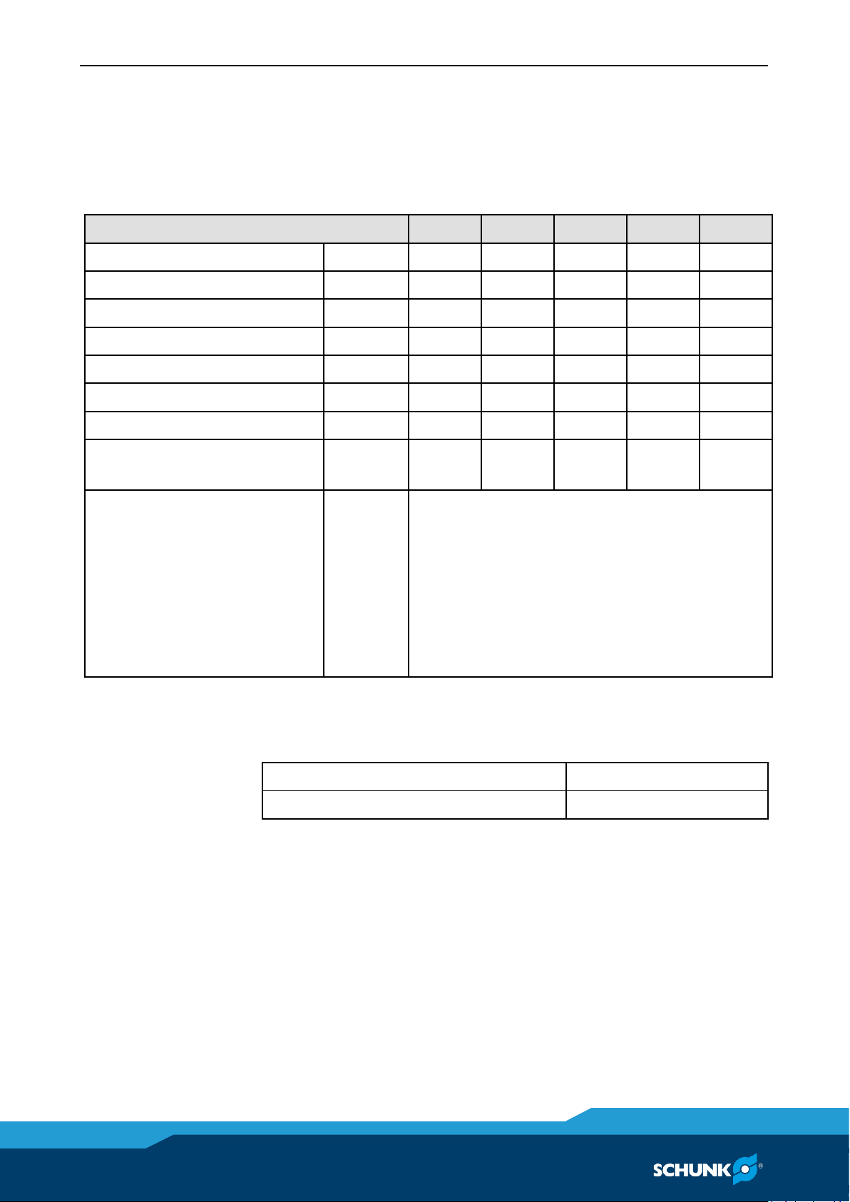
Technical data
Chuck data
(with long base jaws)
ROTA-S flex
550
700
1000
1200
1400
Max. torque
Nm
120
220
280
320
350
Stroke per jaw
mm
7
9.7
12
12
15
Recommended max. speed
min-1
1000
800
500
500
400
Total gripping force max.
kN
100
180
230
270
270
Mass moment of inertia
kg m2
1.6
7.078
25.03
57.89
125.28
Chuck through hole
mm
52
92
102
162
252
Weight with jaws
kg
65
150
360
490
830
Centrifugal torque of the long
base jaws
M
cGB
kgm
0.153
0.5448
1.8
2.66
5.59
Max. jaw center eccentricity in
axial direction (with long base
jaws)
a
max
mm
For the ROTA-S flex chucks it's necessary to
determine those data specific. Calculation
examples are in the chapter "Technology" in
the SCHUNK-lathe-chuck-catalog or in the
chapter "Special jaws/Technology" in the
SCHUNK-power-chuck-catalog. Those catalogs
are also available as download at
www.de.schunk.com.
The recommended max. speed is only valid for max. operating
force and the use of the suitable hard standard stepped jaws.
Warranty and maximum clamping cycles
Length of warranty
60 Months
Maximum clamping cycle number
50 000 Cycles
When using unhardened top jaws or jaws in special design, make
sure that their weight is as low as possible
For soft top jaws or jaws in special design the permissible speed of
the respective cutting task has to be calculated in accordance to
VDI 3106, whereby the maximum standard value may not be
exceeded. The calculated values have to be examined with a
dynamic measurement. Control of function (piston movement and
actuation pressure) has to be accomplished in accordance with the
guidelines of the professional association.
The recommended speed is valid for ROTA-S flex with long base
jaws and SCHUNK stepped block jaws, hard, type STF.
6
6.1

Technical data
04|ROTA-S flex |en
19
In this the base jaws are inserted flush with outer diameter of the
chuck.
Jaw type
SFA 200
SFA 315
SFA 400
SFA 500
SFA 630
Weight / Set [kg]
2.0
5.6
13.5
13.5
40.0
The speed of rotation must be reduced for jaws with a higher
weight!
Max. oscillating diameter – with base jaws type SFG
ROTA-S flex
550
700
1000
1200
1400
Oscillating diameter Ø [mm]
570
755
1000
1265
1400
The chuck is balanced at Q 6.3 at rated speed.
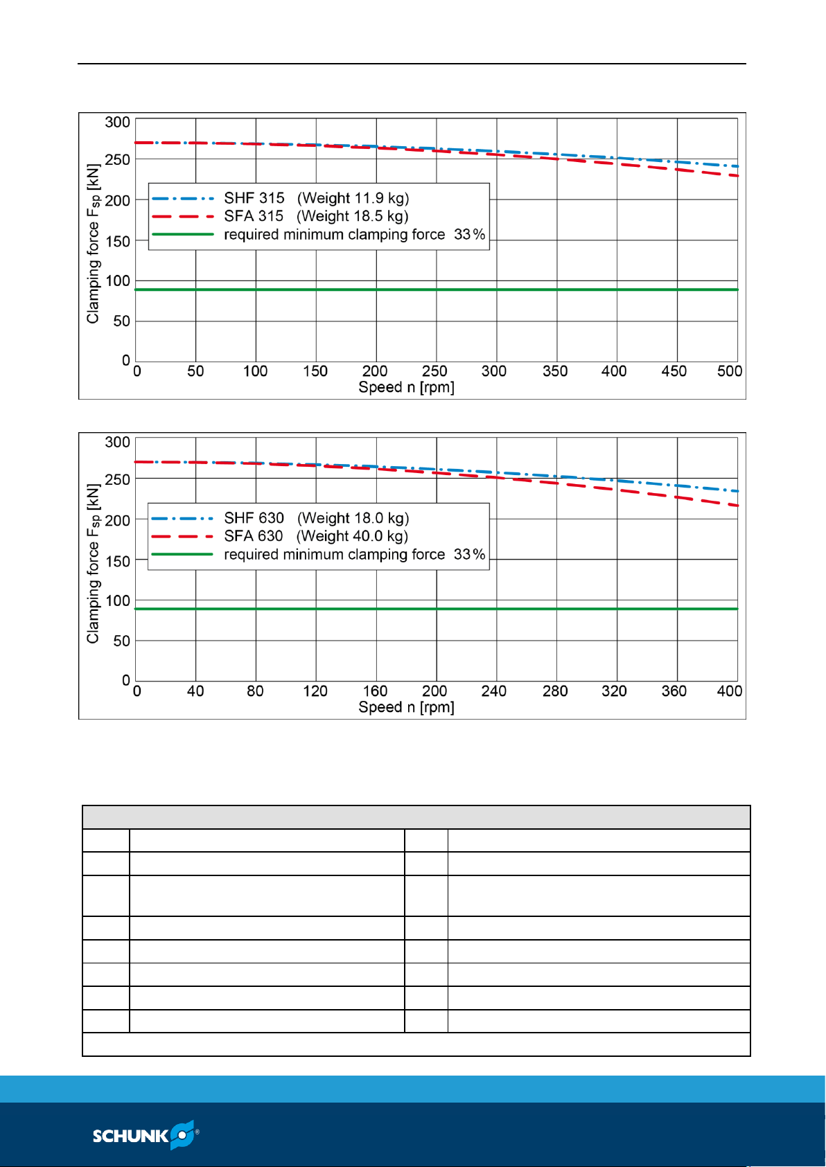
Clamping force / speed diagrams
The diagrams refer to 3-jaw-chuck.
Clamping force-/RPM curves were determined using long, hard
base jaws and hard SHF and SFA standard jaws. During this the
max. actuating force was applied.
The diagrams showing short, hard base jaws and hard SHF and SFA
standard jaws can be found in the ROTA-Splus or ROTA-Splus 2.0
operating manuals contained in the scope of delivery.
The chucks were in good condition and greased with special
SCHUNK grease LINO MAX.
After modification of one or several of these prerequisites the
diagram will no longer be valid.
Chuck set-up for clamping force / speed diagram
F / 3
Clamping force per jaw
S
Center of gravity
rs
Center of gravity radius
[mm]
a
max
Max. jaw eccentricity of
center of gravity in axial
direction
F
max
Actuating force
6.2

Technical data
20
04|ROTA-S flex |en
ROTA-S flex 550 (with long jaws)
ROTA-S flex 700 (with long jaws)
ROTA-S flex 1000 (with long jaws)
Technical data
04|ROTA-S flex |en
21
ROTA-S flex 1200 (with long jaws)
ROTA-S flex 1400 (with long jaws)
Calculations for clamping force and speed
Missing information or specifications can be requested from the
manufacturer.
Legend
Fc
Total centrifugal force [N]
M
cAB
Centrifugal torque of top jaws [Nm]
Fsp
Effective clamping force [N]
M
cGB
Centrifugal torque of base jaws [Nm]
F
spmin
Minimum required clamping force
[N]
n
Speed [rpm]
F
sp0
Initial clamping force [N]
rs
Center of gravity radius [mm]
F
spz
Cutting force [N]
r
sAB
Center of gravity radius of top jaw [mm]
mAB
Mass of one top jaw [kg]
ssp
Safety factor for clamping force
mB
Mass of chuck jaw set [kg]
sz
Safety factor for machining
Mc
Centrifugal force torque [Nm]
Σs
Max. clamping force of chuck [N]
kgm × 9.81 = Nm
6.3

Technical data
22
04|ROTA-S flex |en
Calculation of the required clamping force in case of a given rpm
The initial clamping force F
sp0
is the total force impacting radially
on the workpiece via the jaws due to actuation of the lathe chuck
during shutdown. Under the influence of rotation, the jaw mass
generates an additional centrifugal force. The centrifugal force
reduces or increases the initial clamping force depending on
whether gripping is from the outside inwards or from the inside
outwards.
The sum of the initial clamping force F
sp0
and the total centrifugal
force Fc is the effective clamping force Fsp.
(–) for gripping from the outside inwards
(+) for gripping from the inside outwards
DANGER
Risk to life and limb of the operating personnel and significant
property damage when the RPM limit is exceeded! With
gripping from the outside inwards, and with increasing RPM, the
effective clamping force is reduced by the magnitude of the
increasing centrifugal force (the forces are opposed). When the
RPM limit is exceeded, the clamping force drops below the
required minimum clamping force F
spmin
. Consequently, the
workpiece is released spontaneously.
• Do not exceed the calculated RPM.
• Do not fall below the necessary minimum clamping force.
Reduction in effective clamping force by the magnitude of the total centrifugal force, for gripping from the outside inwards.
6.3.1
Technical data
04|ROTA-S flex |en
23
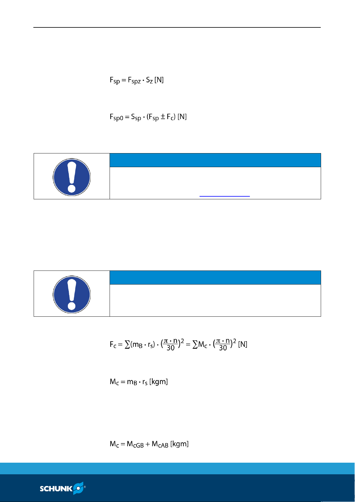
The required effective clamping force for machining Fsp is
calculated from the product of the machining force F
spZ
and the
safety factor Sz. This factor takes into account uncertainties in the
calculation of the machining force. According to VDI 3106: Sz ≥ 1.5.
From this we can derive the calculation of the initial clamping
force during shutdown:
(+) for gripping from the outside inwards
(–) for gripping from the inside outwards
NOTICE
This calculated force must not be larger than the maximum
clamping force ΣS engraved on the chuck.
See also "Chuck data" table (6.1, Page 18)
From the above formula it is evident that the sum of the effective
clamping force Fsp and the total centrifugal force Fc is multiplied by
the safety factor for the clamping force Ssp. According to VDI
3106, the following also applies here: Ssp ≥ 1.5.
The total centrifugal force Fc is dependent on both the sum of the
masses of all jaws and on the center of gravity radius and the rpm.
NOTICE
For safety reasons, in accordance with DIN EN 1550, the
centrifugal force may be a maximum of 67% of the initial
clamping force.
The formula for the calculation of the total centrifugal force Fc is:
For this, n is the given speed of rotation in
RPM
. The product mB ∙ rs
is referred to as the centrifugal force torque Mc.
In case of toolholders with split chuck jaws, i.e., with base jaws and
top jaws, for which the base jaws change their radial position only
by the stroke amount, the centrifugal torque of the base jaws
M
cGB
and the centrifugal torque of the top jaws M
cAB
need to be
added:

Technical data
24
04|ROTA-S flex |en
The centrifugal torque of the base jaws M
cGB
can be found in the
table "Chuck data"(6.1, Page 18). The centrifugal torque of the
top jaws M
cAB
is calculated as per:
Calculation example: required initial clamping force for a given
speed
Required initial clamping force F
sp0
for a given speed n
The following data is known for the machining job:
• Gripping from the outside in (application-specific)
• Machining force F
spz
= 3000 N (application-specific)
• max. speed of rotation n
max
= 3200
rpm
("Chuck data" table)
• RPM n = 1200 rpm (application-specific)
• Mass of one (!) top jaw mAB = 5.33 kg (application-
specific)
• Center of gravity radius of top jaw r
sAB
= 0.107 m (application-
specific)
• Safety factor Sz = 1.5 (according to VDI 3106)
• Safety factor Ssp = 1.5 (according to VDI 3106)
Note: Masses of the jaw mounting screws and T-nuts are not taken
into account.
First the required effective clamping force Fsp is calculated using
the machining force stated:
Initial clamping force during shutdown:
Calculation of total centrifugal force:
For two-part chuck jaws, the following applies:
Centrifugal torque of base jaw and top jaw specified in "Chuck
data" table:
For the centrifugal torque of the top jaw, the following applies:
6.3.2

Technical data
04|ROTA-S flex |en
25
Centrifugal torque for one jaw:
The chuck has 3 jaws, the total centrifugal torque is:
The total centrifugal force can now be calculated:
Initial clamping force during shutdown that was sought:
Calculation of the permissible speed in case of a given initial
clamping force
Calculation of the permissible speed n
perm
in case of a given initial
clamping force F
sp0
The following formula can be used to calculate the permissible
RPM for a given initial clamping force during shutdown:
NOTICE
The calculated permissible RPM may not exceed the maximum
RPM inscribed on the chuck for safety reasons!
Example of calculation: Permissible RPM for a given effective
clamping force
The following data is known from previous calculations:
• Initial clamping force during shutdown F
sp0
= 17723 N
• Machining force for machining job F
spz
3000 N (application-
specific)
• Total centrifugal torque of all jaws ∑Mc = 2.668 kgm
• Safety factor Sz = 1.5 (according to VDI 3106)
• Safety factor Ssp = 1.5 (according to VDI 3106)
NOTE:
Masses of the jaw mounting screws and T-nuts are not taken into
account.
6.3.3

Technical data
26
04|ROTA-S flex |en
Identifying the permissible RPM:
The calculated RPM n
zul
= 1495
rpm
is smaller than the maximum
permissible RPM of the chuck n
max
= 3200
rpm
(see "Chuck data"
table (6.1, Page 18)).
This calculated RPM may be used.
Grades of Accuracy
Tolerances for run-out accuracy and axial run-out accuracy
correspond to the Technical Supply Terms for lathe chucks as per
DIN ISO 3089.
Permissible imbalance
The permissible imbalance for lathe chucks is quality class
G 6.3 as per DIN ISO 1940-1.
6.4
6.5
Attachment of the entire manual chuck
04|ROTA-S flex |en
27
Attachment of the entire manual chuck
The item numbers specified for the corresponding individual
components relate to chapter drawings.(11, Page 33)
Handling prior to attachment
See the ROTA-S plus or ROTA-S plus 2.0Assembly and Operating
Manual contained in the scope of delivery.
Preparing the chuck attachment
• Check the machine table and ready-machined intermediate
flange for radial and axial runout. The permissible limit is 0.005
mm as per DIN 6386 and ISO 3089.
• The contact surface must be chamfered and clean. Rectify any
damage of the machine table contact surfaces.
Assembly of the entire manual chuck
Insert the T-nuts (item 15) into the grooves provided in the
machine table. Then lift the toolholder and supplied eye bolts onto
the machine table. Align centrally with the centering bolts (item 8)
and radially with the location bolts (item 21). Align the chuck and
then attach using the screws (item 14) and the T-nuts. To protect
the counterbore holes against contamination, fit the caps (items 9,
10).
WARNING
Risk of injury from mounting screw brass caps (items 9 and 10)
being flung out when chuck turns.
The mounting screw brass caps (items 9 and 10) must only be
applied for stationary use of the chuck.
7
7.1
7.2
7.3

Function
28
04|ROTA-S flex |en
Function
The item numbers specified for the corresponding individual
components relate to chapter drawings.(11, Page 33)
The manual chuck can be operated in two different modes:
• With guideway extensions and long base jaws.
• Without guideway extensions and with short base jaws
(corresponds to the basic manual chucks ROTA-S plus or ROTAS plus 2.0)
Handling and jaw change
See also the ROTA-S plus or ROTA-S plus 2.0 Assembly and
Operating Manual.
When fitting the cover (item 4) to close the bore, ensure that the
base jaws are mounted first. Then screw the cover (item 4) with
the O-ring (item 18) onto the chuck face using the screws (item
11).
The base jaws must always move under the cover so as to keep the
toolholder through bore sealed. However, the base jaws must only
be moved inwards to the extent that the first tongue and groove
of the base jaws does not move onto the cover (item 4) in the
course of clamping.
If standard jaws are used on the toolholder, the cover (item 4)
cannot be mounted.
With the ROTA-S flex 1000 size, ensure that the indicator pin is not
covered by the cover when screwing on the cover (item 4) observe recess in cover!
Fitting the guideway extensions
The guideway extensions are aligned with the baseplate using the
feather keys (item 19) and screwed to the baseplate using the
screws (item 12).
8
8.1
Function
04|ROTA-S flex |en
29
WARNING
Risk of injury (danger to life and limb) for the operating
personnel and risk of considerable material damage if the
guideway extensions (item 3) are not mounted correctly.
The guideway extensions (item 3) must be screwed to the bracket
(item 2) using the feather keys (item 19) and all the mounting
screws (item 12).
To protect the counterbore holes against contamination, fit the
caps (item 10). Then push in the base jaws (item 6, 7).
See also the ROTA-S plus or ROTA-S plus 2.0 Assembly and
Operating Manual.
WARNING
Risk of injury from mounting screw brass caps (items 9 and 10)
being flung out when chuck turns.
The mounting screw brass caps (items 9 and 10) must only be
applied for stationary use of the chuck.
Important notes on the ROTA-S plus or ROTA-S plus 2.0
manual chuck
See the ROTA-S plus or ROTA-S plus 2.0Assembly and Operating
Manual contained in the scope of delivery.
Checking the ROTA-S plus or ROTA-S plus 2.0 manual chuck
See the ROTA-S plus or ROTA-S plus 2.0Assembly and Operating
Manual contained in the scope of delivery.
8.2
8.3

Maintenance
30
04|ROTA-S flex |en
Maintenance
The item numbers specified for the corresponding individual
components relate to chapter drawings.(11, Page 33)
A high bearing load capacity with a secure workpiece clamping can
only be guaranteed with regular lubrication using a highperformance lubricant. For this reason, we recommend regularly
cleaning the chuck and lubrication using LINO MAX special grease.
The chuck will have to be disassembled and cleaned at regular
intervals according to its application.
CAUTION
Allergic reactions due to grease in contact with skin!
Wear gloves.
Disassembling and assembling the chuck
Remove the base jaws from the chuck as described in chapter
"Handling and jaw change" (8.1, Page 28)
Unscrew the screws (item 33) and remove the guideway extension
(item 4). Screw out the screws (item 33) and undo the ROTA-S flex
from the baseplate (item 3), taking it off to the front.
For further disassembly and assembly of the chuck, see the ROTA-
S plus or ROTA-S plus 2.0 Assembly and Operating Manual.
WARNING
Risk of injury due to dropping the manual chuck during
transport, installation or removal
During transport and when installing or detaching the manual
chuck, ensure it does not fall off.
Jaw change
Clean and lubricate jaws if there is no film of grease.
9
9.1
9.2

Maintenance
04|ROTA-S flex |en
31
At least once a month
Lubricate the chuck at the two lubrication nipples (item 37) on the
circumference of the chuck body (item 1) using a manual press.
Use LINO MAX by SCHUNK as grease.
The chuck must be in fully the open position (jaw change position)
so that all the important areas are covered with grease by the
lubrication system.
• The functional surfaces of the wedge bars (item 5 and 6) and
the drive ring (item 7) are reached via the lubrication nipple
opposite jaw 1. The second greasing area provides the spindle
bearings and the spindle thread with grease.
• After lubricating, open and close the chuck 2 – 3 times without
a workpiece to evenly distribute the grease across all the
functional surfaces.
• Clean the guideway extensions and apply LINO MAX with a
brush.
In the case of decreasing clamping force or after approx. 200
operating hours
If the clamping force decreases, the inside of the chuck is
contaminated or the coolant has washed out or decomposed the
grease.
In this case disassemble the chuck, carefully clean all parts with
degreasing agent and check for wear and damage.
Replace damaged parts with original SCHUNK spare parts only.
Before installation, lubricate parts with LINO MAX special grease.
This cleaning procedure should be performed approx. every 200
operating hours, depending on the extent of strain on the chuck.
9.3
9.4

Spare parts
32
04|ROTA-S flex |en
Spare parts ROTA-S flex
When ordering spare parts, it is imperative to specify the type,
size and above all the manufacturing no of the chuck.
Seals, sealing elements, screw connections, springs, bearings,
screws and wiper bars plus parts coming into contact with the
workpiece are not covered by the warranty.
Item
Designation
Quantity
999
ROTA-S plus 2.0 or ROTA-S plus centering chuck (complete)
1
60
Base plate
1
61
Guideway extension
3
62
Cover
1
64
Pressure bolt
3
63
Long base jaw
3
40
Short base jaw
3
68/69
Centering bolt
2
66
Cover (bore cover)
15
85
Cover (bore cover)
13
71
Countersunk screws
3
70
Cylindrical screws
15
75
Cylindrical screws
3
74
Cylindrical screws
13
73
Nut for T-slot
13
78
Cylindrical screws
12
76
Cylindrical screws
2
80
O-ring
1
77
Feather keys
6
72
Location bolts
1
79
Wiper
3
67
Locking screw
1
20
Spanner wrench
1
65/83
Ratchet with adapter
1
10

Assembly drawing
04|ROTA-S flex |en
33
Assembly drawing
ROTA-S flex
11

34
04|ROTA-S flex |en
Spare parts ROTA-S plus 2.0
When ordering spare parts, it is imperative to specify the type,
size and above all the manufacturing no of the chuck.
Seals, sealing elements, screw connections, springs, bearings,
screws and wiper bars plus parts coming into contact with the
workpiece are not covered by the warranty.
Item
Characterization
Quantity
3 jaws
2 jaws
1
Chuck body
1
1
2
Cover 1 1
3
Drive ring
1
1
4
Base jaw
3
2
5
Wedge bar with thread
1
1
6
Wedge bar
2
1
7
Sliding block
3
2
8
Spindle 1 1
9
Spindle nut
1
1
10
Bearing seat
1
1
11
Wiper (starting for size 200)
3
2
12
Slide 3 2
13
Locking slide
3
2
14
Pressure bolt
3
2
15
Traverse slide
3
2
17
Indicator pin
1
1
30
Cylindrical pin
1
1
31
Compression spring for pressure bolt
3
2
32
Compression spring for locking slide
3
2
33
Spring-loaded pressure piece
3
2
34
Cylindrical screw
3
4
35
Cylindrical screw
3
4
36
Flat lens head screw (starting from size 200)
12
8
37
Lubrication nipple
2
2
38
Compression spring for indicator pin
1
1
39
O-ring 3 2
45
Cylindrical pin
3
2
50
Eye bolt (starting from size 250)
1
1
55
Insert 3 2
99
Assembly key
1
1
12

04|ROTA-S flex |en
35
Assembly drawing
ROTA-S plus 2.0
13

36
04|ROTA-S flex |en
Spare parts ROTA-S plus
When ordering spare parts, it is imperative to specify the type,
size and above all the manufacturing no of the chuck.
Seals, sealing elements, screw connections, springs, bearings,
screws and wiper bars plus parts coming into contact with the
workpiece are not covered by the warranty.
Item
Designation
1
Chuck body
2
Cover
3
Drive ring
4
Base jaws
5
Wedge bar with thread
7
Sliding block
8
Spindle
9
Wedge bar without thread
10
Safety bolt
13
Seat of bearing with bore hole
15
Seat of bearing
17
Indicator pin
18
Ball
19
Cartridge
24
2nd plunger pin
25
The plunger pin
26
Washer
27
Compression spring for plunger pin
28
Compression spring for indicator pin
29
Compression spring for safety bolt
30
Clamping pin
31
Screw for plunger pin
32
Lubrication nipple for spindle
33
Lubrication nipple for chuck body
34
Screw DIN EN ISO 4762 (cover)
35
Screw DIN EN ISO 4762
39
Safety disk (from size ROTA-Splus 500)
40
Compression spring
41
Set-screw
14

04|ROTA-S flex |en
37
Assembly drawing
ROTA-S plus
15
 Loading...