

SCHUNK RP 1212-H, RP 1216-H, RP 1520-H, RP 1216-W, RP 1212-W Assembly And Operating Manual
...
Translation of the Original operating manual
Assembly and Operating Manual
RP / RW / RC
Gripping rotary modules

Imprint
2
03.00 | RP / RW / RC | Assembly and Operating Manual | en | 389392
Imprint
Copyright:
This manual is protected by copyright. The author is SCHUNK GmbH & Co. KG. All rights reserved. Any reproduction, processing, distribution (making available to third parties),
translation or other usage - even excerpts - of the manual is especially prohibited and requires our written approval.
Technical changes:
We reserve the right to make alterations for the purpose of technical improvement.
Document number: 389392
Version: 03.00|24/01/2019|en
© SCHUNK GmbH & Co. KG
All rights reserved.
Dear Customer,
thank you for trusting our products and our family-owned company, the leading techno-
logy supplier of robots and production machines.
Our team is always available to answer any questions on this product and other solutions.
Ask us questions and challenge us. We will find a solution!
Best regards,
Your SCHUNK team
SCHUNK GmbH & Co. KG
Spann- und Greiftechnik
Bahnhofstr. 106 – 134
D-74348 Lauffen/Neckar
Tel. +49-7133-103-0
Fax +49-7133-103-2399
info@de.schunk.com
schunk.com

Table of contents
03.00 | RP / RW / RC | Assembly and Operating Manual | en | 389392
3
Table of contents
1 General.................................................................................................................... 5
1.1 About this manual ................................................................................................5
1.1.1 Presentation of Warning Labels ...............................................................5
1.1.2 Applicable documents ..............................................................................6
1.1.3 Variants..................................................................................................... 6
1.2 Warranty .............................................................................................................. 7
1.3 Scope of delivery ..................................................................................................7
1.4 Accessories ........................................................................................................... 7
1.4.1 Sensors .....................................................................................................7
2 Basic safety notes ................................................................................................... 8
2.1 Intended use......................................................................................................... 8
2.2 Not intended use.................................................................................................. 8
2.3 Constructional changes ........................................................................................8
2.4 Environmental and operating conditions .............................................................9
2.5 Personnel qualification......................................................................................... 9
2.6 Personal protective equipment.......................................................................... 10
2.7 Notes on safe operation ..................................................................................... 10
2.8 Transport ............................................................................................................ 11
2.9 Malfunctions....................................................................................................... 11
2.10 Disposal .............................................................................................................. 11
2.11 Fundamental dangers......................................................................................... 11
2.11.1 Protection during handling and assembly ..............................................12
2.11.2 Protection during commissioning and operation ...................................12
2.11.3 Protection against dangerous movements.............................................12
2.11.4 Protection against electric shock............................................................13
2.12 Notes on particular risks..................................................................................... 14
2.12.1 Variant gripping force maintenance ......................................................15
3 Technical data.........................................................................................................16
4 Design and description............................................................................................17
4.1 Design ................................................................................................................. 17
4.2 Description ......................................................................................................... 17
5 Assembly and settings ............................................................................................18
5.1 Mechanical connection ...................................................................................... 18
5.2 Pneumatic connection........................................................................................ 18
5.3 Settings and options of the GM gripping module... ........................................... 20
5.3.1 GMW / GMP/ GMC modular design.......................................................20
5.3.2 Maintenance of gripping force unit........................................................21
5.3.3 Rotation adapter ....................................................................................21
5.3.4 End position monitoring .........................................................................23
5.4 Settings and options of the RM... rotary module ...............................................24

Table of contents
4
03.00 | RP / RW / RC | Assembly and Operating Manual | en | 389392
5.4.1 Setting the swiveling time ......................................................................24
5.4.2 Setting the speed....................................................................................24
5.4.3 Setting the shock absorber stroke..........................................................25
5.4.4 Adjusting the end positions .................................................................... 26
5.4.5 End position monitoring .........................................................................27
5.4.6 Intermediate stop RZ12/15/21...............................................................29
6 Start-up ..................................................................................................................32
7 Troubleshooting .....................................................................................................33
7.1 Gripper ............................................................................................................... 33
7.1.1 Modul does not move?...........................................................................33
7.1.2 The module does not travel through the entire stroke? ........................33
7.1.3 Module opens or closes abruptly? .........................................................33
7.1.4 Module opens / does it grip the workpiece hard? .................................34
7.1.5 Gripping force is dropping ......................................................................34
7.1.6 Is the gripper not able to grip or hold on to the workpiece? .................34
7.1.7 Module does not achieve the opening and closing times? ...................34
7.2 Rotary module .................................................................................................... 35
7.2.1 End position signal not present? ............................................................35
7.2.2 Does the module not travel through the rotating angle? ......................35
7.2.3 Torque is diminishing..............................................................................35
7.2.4 Product rotates abruptly ........................................................................35
7.2.5 Product does not move smoothly to the end positions .........................36
7.2.6 End position signal not present? ............................................................36
8 Maintenance ..........................................................................................................37
8.1 Maintenance and lubrication, gripping module GM... .......................................37
8.1.1 Maintenance interval .............................................................................37
8.1.2 Lubricants/Lubrication points (basic lubrication) ..................................37
8.2 Maintenance and lubrication, rotary module RM... ........................................... 37
8.2.1 Shock absorber .......................................................................................37
8.2.2 Maintenance and lubrication intervals................................................... 38
8.2.3 Lubricants/Lubrication points................................................................. 38
8.3 Dismantling the module .....................................................................................39
8.4 Assembling the module ...................................................................................... 40
9 Assembly / spare parts ...........................................................................................41
9.1 Gripping module GM... .......................................................................................41
9.1.1 GMWPC assembly drawing.....................................................................41
9.1.2 Seal kit ....................................................................................................43
9.2 RM rotary module... ...........................................................................................43
9.2.1 Assembly drawing................................................................................... 43
9.2.2 Sealing kit ............................................................................................... 44
9.2.3 Shock absorber .......................................................................................44
10 Translation of original declaration of incorporation ................................................45
11 Annex to Declaration of Incorporation....................................................................46

General
03.00 | RP / RW / RC | Assembly and Operating Manual | en | 389392
5
1 General
1.1 About this manual
This manual contains important information for a safe and
appropriate use of the product.
This manual is an integral part of the product and must be kept
accessible for the personnel at all times.
Before starting work, the personnel must have read and understood this operating manual. Prerequisite for safe working is the
observance of all safety instructions in this manual.
Illustrations in this manual are provided for basic understanding
and may differ from the actual product design.
In addition to these instructions, the documents listed under Link
Mitgeltende Unterlagen are applicable.
1.1.1 Presentation of Warning Labels
To make risks clear, the following signal words and symbols are
used for safety notes.
DANGER
Danger for persons!
Non-observance will inevitably cause irreversible injury or death.
WARNING
Dangers for persons!
Non-observance can lead to irreversible injury and even death.
CAUTION
Dangers for persons!
Non-observance can cause minor injuries.
NOTICE
Material damage!
Information about avoiding material damage.

General
6
03.00 | RP / RW / RC | Assembly and Operating Manual | en | 389392
1.1.2 Applicable documents
• General terms of business *
• Catalog data sheet of the purchased product *
• Assembly and Operating manuals of the accessories *
• Assembly and operating manual for RM rotary modules *
• Assembly and operating manual for GM W/P/C gripping modules *
• "GEMOTCE-TOOLBOX Rotation" program *
• "GEMOTEC-KOMBIBOX" program *
(-> for selection of parts list for adaptation of RP/W/C modules
to other modules of the modular system)
The documents marked with an asterisk (*) can be downloaded on
our homepage schunk.com
1.1.3 Variants
This operating manual applies to the following variations:
• RP / RW / RC without gripping force maintenance
• RP / RW / RC with gripping force maintenance (...-K)
• RP / RW / RC with gripping force maintenance (...-S)
Two versions are also available for the RW type:
• Gripper stroke mainly inwards (RWI...)
• Gripper stroke mainly outwards (RWA...)
Type key

General
03.00 | RP / RW / RC | Assembly and Operating Manual | en | 389392
7
1.2 Warranty
If the product is used as intended, the warranty is valid for 24 months
from the ex-works delivery date under the following conditions:
• Observe the specified maintenance and lubrication intervals
• Observe the ambient conditions and operating conditions
Parts touching the workpiece and wear parts are not included in
the warranty.
1.3 Scope of delivery
The scope of delivery includes
• Gripping rotary modules RP / RW / RC in the version ordered
• Exhaust air throttles
• Accessory pack
1.4 Accessories
A wide range of accessories are available for this product
For information regarding which accessory articles can be used
with the corresponding product variants, see catalog data sheet.
1.4.1 Sensors
Overview of the compatible sensors
Designation Type
Inductive proximity switches IN
Gripping movement monitoring set GMNS-...
Rotary movement monitoring set RMNS...
Magnetic switch MMS
• Exact type designation of the compatible sensors see catalog.
• Information on handling sensors is available at schunk.com or
from SCHUNK contact persons.

Basic safety notes
8
03.00 | RP / RW / RC | Assembly and Operating Manual | en | 389392
2 Basic safety notes
2.1 Intended use
The module is designed solely for the gripping and swiveling of
useful loads into any desired position, where the load does not react in a manner endangering persons, property or the environment as a result of this manipulation.
• The product may only be used within the scope of its technical
data, Technical data [}16].
• When implementing and operating components in safety-related parts of the control systems, the basic safety principles in
accordance with DIN EN ISO 13849-2 apply. The proven safety
principles in accordance with DIN EN ISO 13849-2 also apply to
categories 1, 2, 3 and 4.
• The product is intended for installation in a machine/system.
The applicable guidelines must be observed and complied with.
• The product is intended for industrial and industry-oriented use.
• Appropriate use of the product includes compliance with all instructions in this manual.
2.2 Not intended use
It is not intended use if the product is used, for example, as a
pressing tool, stamping tool, lifting gear, guide for tools, cutting
tool, clamping device or a drilling tool.
• Any utilization that exceeds or differs from the appropriate use
is regarded as misuse.
2.3 Constructional changes
Implementation of structural changes
By conversions, changes, and reworking, e.g. additional threads,
holes, or safety devices can impair the functioning or safety of the
product or damage it.
• Structural changes should only be made with the written
approval of SCHUNK.

Basic safety notes
03.00 | RP / RW / RC | Assembly and Operating Manual | en | 389392
9
2.4 Environmental and operating conditions
Required ambient conditions and operating conditions
Incorrect ambient and operating conditions can make the product
unsafe, leading to the risk of serious injuries, considerable material
damage and/or a significant reduction to the product's life span.
See also Environmental and operating conditions [}9].
• Make sure that the product is not exposed to excessive vibrations and/or strokes.
• Ensure that no strong magnetic fields impair the function of the
product.
Contact your SCHUNK partner if the product is to be used in
strong magnetic fields.
• Make sure that the module and the top jaws are a sufficient size
for the application.
2.5 Personnel qualification
Inadequate qualifications of the personnel
If the personnel working with the product is not sufficiently qualified, the result may be serious injuries and significant property
damage.
• All work may only be performed by qualified personnel.
• Before working with the product, the personnel must have read
and understood the complete assembly and operating manual.
• Observe the national safety regulations and rules and general
safety instructions.
The following personal qualifications are necessary for the various
activities related to the product:
Trained electrician
Due to their technical training, knowledge and experience, trained
electricians are able to work on electrical systems, recognize and
avoid possible dangers and know the relevant standards and regulations.
Qualified personnel
Due to its technical training, knowledge and experience, qualified
personnel is able to perform the delegated tasks, recognize and
avoid possible dangers and knows the relevant standards and regulations.
Instructed person
Instructed persons were instructed by the operator about the delegated tasks and possible dangers due to improper behaviour.
Service personnel of
the manufacturer
Due to its technical training, knowledge and experience, service
personnel of the manufacturer is able to perform the delegated
tasks and to recognize and avoid possible dangers.

Basic safety notes
10
03.00 | RP / RW / RC | Assembly and Operating Manual | en | 389392
2.6 Personal protective equipment
Use of personal protective equipment
Personal protective equipment serves to protect staff against
danger which may interfere with their health or safety at work.
• When working on and with the product, observe the occupational health and safety regulations and wear the required personal protective equipment.
• Observe the valid safety and accident prevention regulations.
• Wear protective gloves to guard against sharp edges and
corners or rough surfaces.
• Wear heat-resistant protective gloves when handling hot
surfaces.
• Wear protective gloves and safety goggles when handling hazardous substances.
• Wear close-fitting protective clothing and also wear long hair in
a hairnet when dealing with moving components.
2.7 Notes on safe operation
Incorrect handling of the personnel
Incorrect handling and assembly may impair the product's safety
and cause serious injuries and considerable material damage.
• Avoid any manner of working that may interfere with the function and operational safety of the product.
• Use the product as intended.
• Observe the safety notes and assembly instructions.
• Do not expose the product to any corrosive media. This does
not apply to products that are designed for special environments.
• Eliminate any malfunction immediately.
• Observe the care and maintenance instructions.
• Observe the current safety, accident prevention and environmental protection regulations regarding the product's application field.

Basic safety notes
03.00 | RP / RW / RC | Assembly and Operating Manual | en | 389392
11
2.8 Transport
Handling during transport
Incorrect handling during transport may impair the product's safety
and cause serious injuries and considerable material damage.
• When handling heavy weights, use lifting equipment to lift the
product and transport it by appropriate means.
• Secure the product against falling during transportation and
handling.
• Stand clear of suspended loads.
2.9 Malfunctions
Behavior in case of malfunctions
• Immediately remove the product from operation and report the
malfunction to the responsible departments/persons.
• Order appropriately trained personnel to rectify the malfunction.
• Do not recommission the product until the malfunction has
been rectified.
• Test the product after a malfunction to establish whether it still
functions properly and no increased risks have arisen.
2.10 Disposal
Handling of disposal
The incorrect handling of disposal may impair the product's safety
and cause serious injuries as well as considerable material and environmental harm.
• Follow local regulations on dispatching product components for
recycling or proper disposal.
2.11 Fundamental dangers
General
• Observe safety distances.
• Never deactivate safety devices.
• Before commissioning the product, take appropriate protective
measures to secure the danger zone.
• Disconnect power sources before installation, modification,
maintenance, or calibration. Ensure that no residual energy remains in the system.
• If the energy supply is connected, do not move any parts by
hand.
• Do not reach into the open mechanism or movement area of
the product during operation.

Basic safety notes
12
03.00 | RP / RW / RC | Assembly and Operating Manual | en | 389392
2.11.1 Protection during handling and assembly
Incorrect handling and assembly
Incorrect handling and assembly may impair the product's safety
and cause serious injuries and considerable material damage.
• Have all work carried out by appropriately qualified personnel.
• For all work, secure the product against accidental operation.
• Observe the relevant accident prevention rules.
• Use suitable assembly and transport equipment and take precautions to prevent jamming and crushing.
Incorrect lifting of loads
Falling loads may cause serious injuries and even death.
• Stand clear of suspended loads and do not step into their swiveling range.
• Never move loads without supervision.
• Do not leave suspended loads unattended.
2.11.2 Protection during commissioning and operation
Falling or violently ejected components
Falling and violently ejected components can cause serious injuries
and even death.
• Take appropriate protective measures to secure the danger
zone.
• Never step into the danger zone during operation.
2.11.3 Protection against dangerous movements
Unexpected movements
Residual energy in the system may cause serious injuries while
working with the product.
• Switch off the energy supply, ensure that no residual energy remains and secure against inadvertent reactivation.
• Never rely solely on the response of the monitoring function to
avert danger. Until the installed monitors become effective, it
must be assumed that the drive movement is faulty, with its action being dependent on the control unit and the current operating condition of the drive. Perform maintenance work, modifications, and attachments outside the danger zone defined by
the movement range.

Basic safety notes
03.00 | RP / RW / RC | Assembly and Operating Manual | en | 389392
13
• To avoid accidents and/or material damage, human access to
the movement range of the machine must be restricted. Limit/
prevent accidental access for people in this area due through
technical safety measures. The protective cover and protective
fence must be rigid enough to withstand the maximum possible
movement energy. EMERGENCY STOP switches must be easily
and quickly accessible. Before starting up the machine or automated system, check that the EMERGENCY STOP system is
working. Prevent operation of the machine if this protective
equipment does not function correctly.
2.11.4 Protection against electric shock
Possible electrostatic energy
Components or assembly groups may become electrostatically
charged. When the electrostatic charge is touched, the discharge
may trigger a shock reaction leading to injuries.
• The operator must ensure that all components and assembly
groups are included in the local potential equalisation in accordance with the applicable regulations.
• While paying attention to the actual conditions of the working
environment, the potential equalisation must be implemented by
a specialist electrician according to the applicable regulations.
• The effectiveness of the potential equalisation must be verified
by executing regular safety measurements.

Basic safety notes
14
03.00 | RP / RW / RC | Assembly and Operating Manual | en | 389392
2.12 Notes on particular risks
WARNING
Risk of injury from crushing and impacts!
Serious injury could occur during the base jaw procedure and
when breaking or loosening the gripper fingers.
• Wear suitable protective equipment.
• Do not reach into the open mechanism or the movement area
of the product.
WARNING
Risk of injury from objects falling and being ejected!
Falling and ejected objects during operation can lead to serious
injury or death.
• Take appropriate protective measures to secure the danger
zone.
WARNING
Risk of injury from unexpected movements!
If the energy supply is switched on or residual energy remains in
the system, parts may move unexpectedly and cause serious injuries.
• Switch off the energy supply.
• Make sure no residual energy is in the system.
WARNING
Risk of injury from rotating components!
In the case of swivel units or rotary tables with a rotary drive, serious injuries can be caused by rotating components.
• Take appropriate protective measures to secure the danger
zone.

Basic safety notes
03.00 | RP / RW / RC | Assembly and Operating Manual | en | 389392
15
2.12.1 Variant gripping force maintenance
WARNING
Risk of injury from objects falling during energy supply failure
Products with a mechanical gripping force maintenance can, during energy supply failure, still move independently in the direction specified by the mechanical gripping force maintenance.
• Secure the end positions of the product with SCHUNK SDV-P
pressure maintenance valves.
WARNING
Risk of injury due to uncontrolled movements!
While disassembling uncontrolled movements of the gripper's individual parts of grippers with gripping force maintenance may
cause serious injuries.
• Switch off the energy supply.
• Ensure there is no residual energy in the system.
• Disassemble the gripper carefully.

Technical data
16
03.00 | RP / RW / RC | Assembly and Operating Manual | en | 389392
3 Technical data
Designation RP / RW / RC ... RP / RW / RC ... - K / S
Angle of rotation [°] - 5 ... 185
Pressure medium Compressed air, compressed air quality according to
ISO 8573-1:7 4 4
Min. pressure [bar] 3 5
Max. pressure [bar] 8
Nominal working pressure [bar] 6
Max. permissible finger length [mm]
RP / RW / RC Size
... 12 ... 16 ... 20 ... 28
Max. permissible finger length [mm]
RP... 40 50 75 100
RW... 25 30 35 40
RC... 40 50 75 100
Max. permitted weight per finger [kg]
RP / RW / RC Size
... 12 ... 16 ... 20 ... 28
Max. permitted weight per finger [kg]
RP... 0.06 0.1 0.18 0.35
RW... 0.05 0.075 0.1 0.13
RC... 0.06 0.1 0.18 0.35
The pneumatic piston of the gripper has different piston surface
designs for opening and closing the gripper. This results in different gripping forces during opening and closing. This must be taken
into account when implementing and operating the gripper.
More technical data is included in the catalog data sheet.
Whichever is the latest version.
Environmental and operating conditions
Designation RP / RW / RC
Ambient temperature [°C]
min.
max.
+5
+60
IP protection class * 40
Noise emission [dB(A)] ≤ 70
*
For use in dirty ambient conditions (e.g. sprayed water, vapors,
abrasion or processing dust) SCHUNK offers corresponding
product options as standard. SCHUNK also offers customized
solutions for special applications in dirty ambient conditions.

Design and description
03.00 | RP / RW / RC | Assembly and Operating Manual | en | 389392
17
4 Design and description
4.1 Design
The entire modular system for the production of parallel gripping rotary
modules RP-... and angular gripping rotary modules RW-... as well as
three-jaw gripping rotary modules RC-... is illustrated in the following.
Modular design
1 3-jaw gripper kit (GCB) 5 Rotation adapter (GMD)
2 Parallel gripper kit (GPB) 6 Rotary module (RM)
3 Angle gripper kit (GWB) 7 Drive unit (GMA)
4 Intermediate stop (RZ) 8 Gripping force maintenance unit (GKS)
4.2 Description
Gripping rotary modules of this series have a module design:
• GMW/P/C gripper, consisting of
– Gripper kit G...B
– GMD rotation adapter (optional)
– GMA drive unit
– Gripping force safety device, GKS (optional)
• Flat Swivel Unit RM-F
All components are separated by function; all characteristics of the
individual modules are maintained.
• Additional details ☞ Catalog data sheet.
• The design is shown in the chapter "Complete design" Design [}17].

Assembly and settings
18
03.00 | RP / RW / RC | Assembly and Operating Manual | en | 389392
5 Assembly and settings
NOTICE
Material damage due to improper assembly!
• When mounting loads, do not allow impermissible forces and
moments to be exerted (see catalog data sheet).
• Select a suitable tightening torque when assembling the
product or loads on the product in accordance with the generally accepted guidelines for screw connections.
• Secure all screws using a suitable chemical screw lock.
5.1 Mechanical connection
Evenness of the
mounting surface
The values apply to the whole mounting surface to which the
product is mounted.
Requirements for evenness of the mounting surface (Dimensions in mm)
Edge length Permissible unevenness
< 100 < 0.02
> 100 < 0.05
RP/W/C ... Gripper rotary modules are fastened at the side on the
base body.
Furthermore, connection geometries for the top jaws can be found
on the base jaws.
Dimensions for the position and size of the connection geometries,
Catalog data sheet of the product .
Mounting
Ø Mount the module using the fixing bores provided.
Ø Mount the modules using the fixing bores provided.
Ø Attach the top jaws using the mounting bores provided.
5.2 Pneumatic connection
NOTICE
Damage to the rotary module possible!
The rotary module can be damaged if it arrives too abruptly in
the end position.
• The rotary motion must reach the end position without jerk or
bounce.
• Therefore, shock absorbers must be used Adjusting the end
positions [}26].
• Please observe the information in the catalog pages.

Assembly and settings
03.00 | RP / RW / RC | Assembly and Operating Manual | en | 389392
19
NOTICE
Pressure medium:
The unit must not under any circumstances be operated with
oiled air before operation with unoiled air (washing out of factory
lubrication).
NOTICE
One-way flow control valves must be installed at the air connections for operation.
Alternatively, hose throttles can also be used.
NOTE
• Observe the requirements for the compressed air supply,
Technical data [}16].
• In case of compressed air loss (cutting off the energy line), the
components lose their dynamic effects and do not remain in a
secure position. However, the use of a SDV-P pressure maintenance valve is recommended in this case in order to maintain the
dynamic effect for some time. Product variants are also offered
with mechanical gripping force via springs, which also ensure a
minimum clamping force in the event of a pressure drop.
Use connecting wires with the same or a larger cross-section as
the connection thread.
See the catalog for precise information about the position and size
of the connection geometries.
Air connections
Connection Function
A Clockwise rotation (direction of arrow)
B Counterclockwise rotation
C Open gripper
D Close gripper

Assembly and settings
20
03.00 | RP / RW / RC | Assembly and Operating Manual | en | 389392
5.3 Settings and options of the GM gripping module...
5.3.1 GMW / GMP/ GMC modular design
The GM modules have a modular design.
The main window consists of:
• Gripper kit: GWB / GCB / GPB
• Drive unit: GMA
The basis module can be expanded by ordering options and ac-
cessories.
Design of the GM.... modules
GWB Angle gripper kit GMD Rotation adapter
GPB Parallel gripper kit GMA Drive unit
GCB 2-jaw gripper kit GKS Gripping force maintenance device

Assembly and settings
03.00 | RP / RW / RC | Assembly and Operating Manual | en | 389392
21
5.3.2 Maintenance of gripping force unit
To maintain secure the gripping force in case of a drop in pressure,
an additional module can be integrated without any additional
parts.
Optionally, the maintance of gripping force unit is available in the
direction of clamping or spreading.
Modifying from
clamping direction to
spreading direction
The GKS is completely seperated (GKS1...9) from the gripper.
Ø Remove the rod (2)downwards.
Ø Mount the safety disc (8) in the lower groove of the rod.
Ø Insert the rod fromaboveinto the GKS.
Modifying from
spreading direction to
the clamping direction.
The GKS is completely seperated (GKS1...9) from the gripper.
Ø Remove the rod (2)upwards.
Ø Mount the safety disc (8) in the lower groove of the rod.
Ø Insert the rod frombelowinto the GKS.
Order numbers of the maintenance of gripping force unit:
• GKE 12 for GMW/ GMP/ GMC 12 gripping module
• GKE 16 for GMW/ GMP/ GMC 16 gripping module
• GKE 20 for GMW/ GMP/ GMC 20 gripping module
• GKE 28 for GMW/ GMP/ GMC 28 gripping module
When ordering a gripping module including a gripping force main-
tenance unit as described in the catalog, the gripping force maintenance unit will have already been installed by SCHUNK.
5.3.3 Rotation adapter
A GMD-...rotation adapter is available for step-less turning of the
GWB / GWP / GWC gripper kit and drive out.
This is installed between the gripper kit and drive unit.
ID no. of the rotation adapter
Rotation adapter for Designation ID number
GMW / GMP / GMC 12 GMD 12 5507895
GMW / GMP / GMC 16 GMD 16 5507896
GMW / GMP / GMC 20 GMD 20 5507897
GMW / GMP / GMC 28 GMD 28 5507898
When ordering a gripper module including a rotation adapter as
described in the catalog, the rotation adapter will have already
been installed by SCHUNK.

Assembly and settings
22
03.00 | RP / RW / RC | Assembly and Operating Manual | en | 389392
Bore out position
In addition to clamping with the clamping screw, the position of
the adapter can secured by drilling with ø4 and pinning.
For this purpose the plate of the adapter is pre-drilled
NOTICE
Risk of damage to the piston rod if the rotary adapter is drilled
and pinned.
• Observe drilling depth – see table.
Drilling depth
Adapter drilling depth A
GMD 12 12.3 mm
GMD 16 15.3 mm
GMD 20 16.0 mm
GMD 28 20.0 mm

Assembly and settings
03.00 | RP / RW / RC | Assembly and Operating Manual | en | 389392
23
5.3.4 End position monitoring
To monitor the end positions, standardized monitoring sets for direct installation are available.
The installation of up to four monitoring sets is possible for the
GMW/P/C 16, GMW/P/C 20, and GMW/P/C 28 types, whereby
four gripper jaws positions can be monitored.
For the GMW/P/C 12 type, only two monitoring sets can be installed.
The end-to-end piston rod in the GMA drive unit GMW / GMP/
GMC modular design [}20] is monitored.
Proximity switch monitoring: GMNS-...
The monitoring set's scope of delivery includes the following:
• 1x retaining plate
• 1x proximity switch
• 1x connection cable
Position of the proximity switches at the GMW is analogous to the GMC and GMP
1 Proximity switch (GMNS-...)
Assembly of the endposition monitoring
Ø Disassemble the drive unit or, if need be, the maintenance of
gripping force unit.
Ø Push the holding piece into the drive unit.
Ø Reassemble the drive unit or, if need be, the maintenance of
gripping force unit.
Ø Push the sensor into the holding piece and clamp with the fixing
screw in the holding piece. This is also accessible when the
cover is mounted or when the maintenance of gripping force
unit is installed.
Setting the
monitoring
Ø Undo the attachment screw in the drive unit.
Ø Set the sensor via the holding piece.
Ø Fix the sensor via the attachment screw.

Assembly and settings
24
03.00 | RP / RW / RC | Assembly and Operating Manual | en | 389392
5.4 Settings and options of the RM... rotary module
5.4.1 Setting the swiveling time
The catalog data sheet contains data for the swiveling time.
The swiveling time is set with exhaust air throttles, these can be
found in the accessory pack.
NOTICE
The required swiveling time cannot usually be achieved through
merely adjusting the throttles!
To achieve the swiveling time, you always need to set/adjust the
end position dampening, too.
5.4.2 Setting the speed
NOTICE
Risk of damage to the product!
If the end position is approached too hard, the product may be
damaged.
• Adjust exhaust throttle valve and shock absorber so that the
movement is braked smoothly.
Ø Close exhaust throttle valve completely.
Ø Open exhaust throttle valve until the product starts to move.
Ø Continue to open the exhaust throttle valve incrementally until
the movement decelerates smoothly.
✓ If the speed is too low, the product will brake too soon and
the end position will be reached too slowly.
✓ If the speed is too high, the product will impact against the
end position and the shock absorber will be overloaded.

Assembly and settings
03.00 | RP / RW / RC | Assembly and Operating Manual | en | 389392
25
NOTE
A smooth motion may also be too slow in many use-cases.
Further settings can be made via the shock absorbers, Setting the
shock absorber stroke [}25].
5.4.3 Setting the shock absorber stroke
NOTE
When received from the factory, the unit is set to utilize the maximum shock absorber stroke.
Movement
Target position
End position
Target time
Time T
Damping
The shock absorber stroke is too long and the end position is
reached too slowly.
Movement
Target position
End position
Target time
Time T
Damping
The shock absorber stroke is too short and the unit arrives in the
end position too abruptly.
Movement
Target position
End position
Target time
Time T
Damping
Optimal shock absorber stroke.

Assembly and settings
26
03.00 | RP / RW / RC | Assembly and Operating Manual | en | 389392
5.4.4 Adjusting the end positions
The following parts are included within the scope of delivery for
angle of rotation fine adjustment and adjustment of the end position
dampening to the mass moment of inertia occurring in operation.
• Stop coupling (10)
• Counter nut (11)
• Counter nut (12)
• Shock absorber (18)
Adjustment of end position RM12/15/21
Angle of rotation
fine adjustment
Ø Release counter nut (11).
Ø Each end position can be adjusted to any angle between -5° and
+90° by twisting the stop coupling (10) with the shock absorber
(18) integrated in it.
Ø Tighten the stop coupling again with the counter nut.
Dampening adjustment
NOTICE
Use the shock absorber!
Operation without the shock absorber included within the scope
of delivery is not permitted.
• Ocserve the maximum mass moment of inertia (see catalog).
• Adjust the dampening at the mass moment of inertia.
• See chapterSetting the swiveling time [
}
24].
■ The desired angle of rotation has been set.
Ø Release counter nut (12).
Ø By turning the shock absorber (18) in and out, the stroke of the shock
absorber (and therefore the shock absorber characteristic curve) can
be adjusted to the mass moment of inertia occurring in operation.
✓ The previously adjusted angle of rotation is not influenced by this.
Ø Tighten the absorber again with the counter nut.
Assembly and settings
03.00 | RP / RW / RC | Assembly and Operating Manual | en | 389392
27
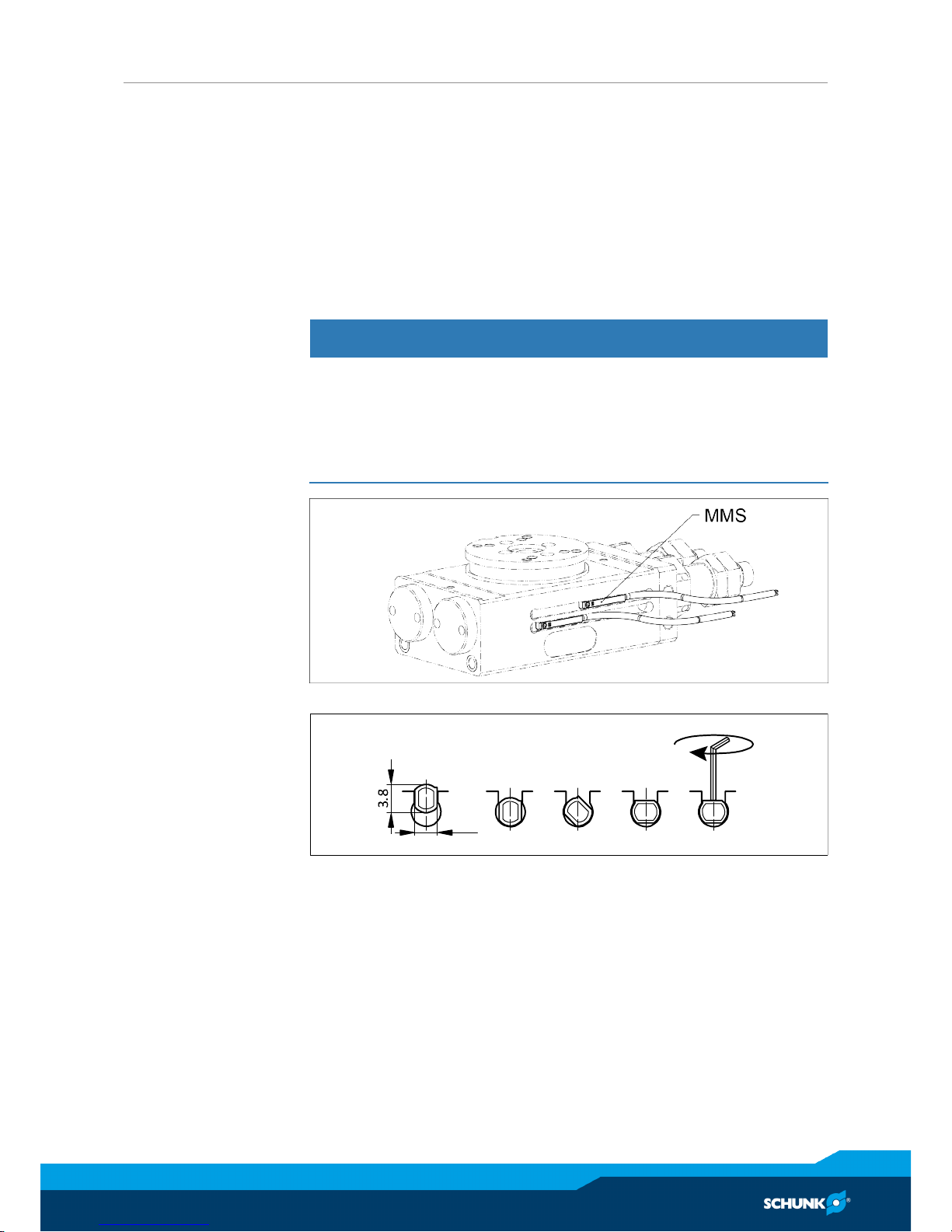
5.4.5 End position monitoring
Two options are available for the end positions monitoring:
• By magnet sensors MMS
• By inductive sensors via standardized monitoring sets
Attachment / adjustment MMS magnet
sensors
With the MMS sensor, the magnet integrated in the piston is monitored.
NOTICE
Material damage due to an incorrect tightening torque!
If the threaded pin is tightened with an incorrect tightening
torque, the product may be damaged.
• Observe a maximum tightening torque of 10 Ncm for the set-
screws.
MQL sensor attachment
3.0
Max.
10 Ncm
For monitoring of the two end positions, one sensor each is installed.
■ Piston is in the respective end position.
Ø Turn the sensor into the groove.
Ø Push the sensor into the groove until the signal is present at the
output.
Ø Fix the magnetic switch into this position by tightening the set-
screw with the Allen key.
Ø If need be, repeat the procedure with the second sensor and
the opposing piston position.

Assembly and settings
28
03.00 | RP / RW / RC | Assembly and Operating Manual | en | 389392
Attachment / adjustment of the RMNS
and RMNZ monitoring sets
For the RMNS and RMNZ monitoring sets, the control cam integrated in the rotary table is inductively monitored.
RMNS-12
Proximity switch monitoring sets for:
• RM rotary module...: RMNS-12
• Intermediate stop, RZ...: RMNZ-12*
Scope of delivery of the monitoring sets:
• 1x retaining plate
• 2x (1x*) control cam
• 2x (1x*) proximity switch
• 2x (1x*) connection cable
Setting the
monitoring
■ Piston is at the respective end or intermediate position.
■ The proximity switch is set to the switching condition.
When the RMNZ is used, the cam is offset to the RMNS cam...
Ø Undo the attachment screw.
Ø Push the control cam in the prism slot of the rotary table until
the signal is present.
Ø Fix the control cam via the attachment screw.

Assembly and settings
03.00 | RP / RW / RC | Assembly and Operating Manual | en | 389392
29
5.4.6 Intermediate stop RZ12/15/21
Intermediate stops are additional modules for rotation modules
and are available for the sizes RM12, RM15 and RM21.
The intermediate position can be adjusted over the entire range of
rotation of the rotary module.
The intermediate stop is installed in the delivery state as shown.
Intermediate stop
The RZL... and RZK... stop pistons are used as stops and for playfree clamping of the intermediate position.
• For the intermediate position 0°-90°, RZK... and RZL... stop pistons are as shown.
• For the intermediate position 90°-180°, RZK... and RZL... stop
pistons are swapped.

Assembly and settings
30
03.00 | RP / RW / RC | Assembly and Operating Manual | en | 389392
5.4.6.1 Adjustment RZ...
■ The stop pistons are mounted as shown in the respective
chapter "RZ12/15/21 intermediate stop" Intermediate stop
RZ12/15/21 [}29] (Attention! Ranges 0°-90°; 90°-180°).
Ø Apply pressure to connections A and C.
Ø Loosen the counter nuts of both stops (5).
Ø Set the stop to the desired position by rotating the RZL... stop
(at 1).
Ø By turning the RZK...(at 1) stop, adjust until the stop clamps the
intermediate position without play.
Ø Secure both stops again with the counter nut.
5.4.6.2 Control RZ...
■ The intermediate stop is set.
Ø The positions can be controlled in accordance with the follow-
ing table.
Ø Check the positions in accordance with the recess at the rotary
table (Fig. "intermediate stop", black arrows Intermediate stop
RZ12/15/21 [}29]).
Possible control
Rotating motion
Air connections
A B C
0° -> 180° 1 0 0
180° -> 0° 0 1 0
0° -> 90° 0 1 1
90° -> 0° 0 1 0
0° -> 90° 0 1 1
90° -> 180° 1 0 0 *
180° -> 90° 1 0 1
90° -> 180° 1 0 0
180° -> 90° 1 0 1
90° -> 0° 0 1 0 *
* after about 0.1 s

Assembly and settings
03.00 | RP / RW / RC | Assembly and Operating Manual | en | 389392
31
5.4.6.3 Dampening adjustment RZ...
The dampening adjustment is done by insertion of disk ("X") under
the shock absorber (9) Intermediate stop RZ12/15/21 [}29].
Ø Disassemble the piston (3), stop sleeve (2) and shock absorber (9).
Ø Insert disks in accordance with the following table between the
piston and the stop sleeve until the desired dampening adjustment has been reached NOTICE!Observe the maximum dis-
tance..
Ø Reinstall the components Intermediate stop RZ12/15/21 [
}
29].
Distances for dampening adjustment
Module RZ12 RZ15 RZ21
Disk "X" DIN 433-3.2-St. DIN 433-3.2-St. DIN 126-5.5-St.
Max. distance
[mm]
2 2 5
5.4.6.4 Position monitoring RZ...
For monitoring of the intermediate position, the RMNZ-... monitoring set is available.
This monitoring set is identical with the RMNS-... end positions
monitoring set but it has only control cam.

Start-up
32
03.00 | RP / RW / RC | Assembly and Operating Manual | en | 389392
6 Start-up
• Check the Technical SpecificationsTechnical data [}16].
• Check the permissible loading specifications (see catalog).
• Do not use the module until trouble-free operation has been
checked taking all permissible operating parameters into account.
• The movement speed is ideally regulated via throttle check
valves . The speed is always set so that it starts at a low speed
and increases to a higher speed until the desired operating
spePneumatic connection [}18]ed has been reached.
• The movement speed is ideally regulated via throttle check
valves Pneumatic connection [}18]. The speed is always set so
that it starts at a low speed and increases to a higher speed until the desired operating speed has been reached.
• Operate the device in such a way that the permissible cycle
number per minute is not exceeded. Use the "Gemotec Toolbox" program for calculation (schunk.com).
NOTICE
Risk of mechanical damage of the module!
The module must always be adjusted so that no mechanical impacts are produced when reaching the end position.
Dies gilt sowohl für den Betrieb der Schwenkeinheit als auch für
den Betrieb des Greifers (entgegen der Greifrichtung).

Troubleshooting
03.00 | RP / RW / RC | Assembly and Operating Manual | en | 389392
33
7 Troubleshooting
7.1 Gripper
7.1.1 Modul does not move?
Possible cause Corrective action
Base jaws jam in housing, e.g. mounting surface is not sufficiently even.
Check the evenness of the mounting surface.
Mechanical connection [}18].
Loosen the mounting screws of the product
and actuate the product again.
Pressure drops below minimum. Check air supply. Pneumatic connection
[}18]
Compressed air lines switched. Check compressed air lines.
Proximity switch defective or set incorrect. Readjust or change sensor.
Component part defective. Replace component or send it to SCHUNK
for repair.
7.1.2 The module does not travel through the entire stroke?
Possible cause Corrective action
Dirt deposits in the mechanical elements. Clean and lubricate product.. Maintenance
[}37]
Pressure drops below minimum. Check air supply., Pneumatic connection
[}18]
Mounting surface is not sufficiently flat. Check the evenness of the mounting sur-
face.. Mechanical connection [}18]
Component part defective. Send product with a SCHUNK repair order or
dismantle product.
7.1.3 Module opens or closes abruptly?
Possible cause Corrective action
Too little grease in the mechanical guiding
areas.
Clean and lubricate product. Maintenance
[}37]
Compressed air lines blocked. Check compressed air lines of damage.
Mounting surface is not sufficiently flat. Check the evenness of the mounting surface.
Mechanical connection [}18]
Pressure drops below minimum. Check air supply. Pneumatic connection
[}18]

Troubleshooting
34
03.00 | RP / RW / RC | Assembly and Operating Manual | en | 389392
7.1.4 Module opens / does it grip the workpiece hard?
Possible cause Corrective action
Exhaust throttle defective. Replacing the exhaust air throttle.
Stroke speed too high. Setting the exhaust air throttle.
7.1.5 Gripping force is dropping
Possible cause Corrective action
Compressed air can escape. Check seals, if necessary, disassemble the
product and replace seals.
Too much grease in the mechanical move-
ment space.
Clean and lubricate product.
Maintenance [}37]
Pressure drops below minimum. Check air supply.
Link Pneumatischer Anschluss
Component part defective. Replace component or send it to SCHUNK
for repair.
7.1.6 Is the gripper not able to grip or hold on to the workpiece?
Possible cause Corrective action
The workpiece weighs too much Use a larger gripping module
The gripper jaws are too long Place the gripping point further inside
Non-optimal engineering design Adapt the engineering design – form-fit grip-
ping
7.1.7 Module does not achieve the opening and closing times?
Possible cause Corrective action
Compressed air lines are not installed optimally.
Check compressed air lines.
Inner diameters of compressed air lines are
of sufficient size in relation to compressed
air consumption.
Keep compressed air lines between the
product and directional control valve as
short as possible.
Flow rate of valve is sufficiently large relat-
ive to the compressed air consumption.

Troubleshooting
03.00 | RP / RW / RC | Assembly and Operating Manual | en | 389392
35
7.2 Rotary module
7.2.1 End position signal not present?
Possible cause Corrective action
Precisely adjust the sensor for the stop Readjust the sensor
Proximity switch defective or set incorrect. Replace sensor
Cable breakage Replacing the sensor cable
7.2.2 Does the module not travel through the rotating angle?
Possible cause Corrective action
The end positions are incorrectly adjusted Readjust the end positions
Pressure drops below minimum. Check air supply.
Pneumatic connection [}18]
Mounting surface is not sufficiently flat. Check the evenness of the mounting surface.
Mechanical connection [}18]
Component part defective. Send product with a SCHUNK repair order or
dismantle product.
Shock absorber defective Check or, if need be, replace the shock ab-
sorber
7.2.3 Torque is diminishing
Possible cause Corrective action
Seals of the drive piston defective. Send product with a SCHUNK repair order or
dismantle product.
Replace the seals.
Positioning of the swivel table defective. Send product with a SCHUNK repair order or
dismantle product.
Compressed air lines blocked. Check compressed air lines of damage.
Pressure drops below minimum. Check air supply., Pneumatic connection
[}18]
7.2.4 Product rotates abruptly
Possible cause Corrective action
Seals of the drive piston defective. Send product with a SCHUNK repair order or
dismantle product.
Replace the seals of the drive piston.
Positioning of the swivel table defective. Send product with a SCHUNK repair order or
dismantle product.
Compressed air lines blocked. Check compressed air lines of damage.

Troubleshooting
36
03.00 | RP / RW / RC | Assembly and Operating Manual | en | 389392
7.2.5 Product does not move smoothly to the end positions
Possible cause Corrective action
Fine adjustment of the absorber stroke is
faulty.
Adjust absorber stroke., Adjusting the end
positions [}26]
Absorber defective. Replace and readjust absorbers., Adjusting
the end positions [}26]
Exhaust throttle defective. Replacing the exhaust air throttle.
Speed of rotation too high. Setting the exhaust air throttle.
7.2.6 End position signal not present?
Possible cause Corrective action
Precisely adjust the sensor for the stop Readjust the sensor Link Endlagen Abfrage
Proximity switch defective or set incorrect. Readjust or change sensor.
Cable breakage Replacing the sensor cable

Maintenance
03.00 | RP / RW / RC | Assembly and Operating Manual | en | 389392
37
8 Maintenance
8.1 Maintenance and lubrication, gripping module GM...
8.1.1 Maintenance interval
NOTICE
Material damage due to hardening lubricants!
Lubricants harden more quickly at temperatures above 60°C,
leading to possible product damage.
• Reduce the lubricant intervals accordingly.
Interval [Mio. cycles] 2
8.1.2 Lubricants/Lubrication points (basic lubrication)
SCHUNK recommends the lubricants listed.
During maintenance, treat all greased areas with lubricant. Thinly
apply lubricant with a lint-free cloth.
Lubricant point Lubricant
Lever mechanism, connecting member, other mechanical sliding points Isoflex-Topas NCA 52
Klüber
All seals *
Bore hole at the piston *
* Only after disassembling the module for repairs
8.2 Maintenance and lubrication, rotary module RM...
8.2.1 Shock absorber
NOTICE
Serious mechanical damage due to failure of the shock absorbers.
The shock absorbers have a limited service life span. A shock absorber failure can lead to serious mechanical damage; for this
reason, they must be checked regularly for proper function. The
shock absorber is working correctly if the device reaches its end
position swiftly without any mechanical impact.
Overloading of the unit or exceeding the permitted swivel speed
can lead to drastic reduction of the service life.
• Determine the swiveling times and the permitted stroke fre-
quency with "Gemotec Toolbox".
• Regularly check the shock absorber.
• Observe the recommended maintenance intervals.

Maintenance
38
03.00 | RP / RW / RC | Assembly and Operating Manual | en | 389392
8.2.2 Maintenance and lubrication intervals
NOTICE
Material damage due to hardening lubricants!
Lubricants harden more quickly at temperatures above 60°C,
leading to possible product damage.
• Reduce the lubricant intervals accordingly.
Interval (million cycles) Maintenance work
2 Check for leaks
4
(recommendation)
Re-lubricate the gear rack
and pinion unit (RM-F 15,
RM-F 21)
2
Variant for
sizes 12 and 15:
6
Replace shock absorber
Recommendation for safe operation
8.2.3 Lubricants/Lubrication points
• All product bearings are life-time lubricated and do not need to
be re-lubricated.
• When disassembling the product for repairs, all bearings have
to be cleaned and re-lubricated.
Lubrication point, Lubricant
Lubricant point Lubricant
Gear rack and pinion unit *
Isoflex-Topas NCA 52
(from Klüber)
All seals **
Rolling element and sliding sur-
faces of the bearings **
* For RM06/08/10/12, only after disassembly of the prodct for repairs
** All products, only after disassembly of the product for repairs
Gear rack and pinion
unit greasing area
(RM15, RM21 only)
Ø Lubricate the product at the designated areas.

Maintenance
03.00 | RP / RW / RC | Assembly and Operating Manual | en | 389392
39
8.3 Dismantling the module
NOTICE
A high degree of expertise is required for the disassembly and
assembly of the module, Personnel qualification [}9].
The repair or elimination of defects by the customer on the module results in the termination of the warranty and liability for all
resulting warranty and subsequent damage.
• It is recommended to have SCHUNK repair damaged and de-
fective modules.
WARNING
Risk of injury when the machine/system moves unexpectedly!
Switch off power supply.
Design of the GM... modules

Maintenance
40
03.00 | RP / RW / RC | Assembly and Operating Manual | en | 389392
WARNING
Components for the maintenance of gripping force unit are under spring tension (except for the GKS rod, item 2)
• It is recommended to have damaged and defective modules
repaired in the production facility. Please consult your
SCHUNK contact person.
• To remove the GKS spring, secure the lock washer and circlip
(GKS items 6, 8 and 9) with a suitable device against jumping out.
• Disassemble the module as shown in the "Assembly drawings",
Assembly / spare parts [}41].
• Only disassemble the rotation module for repair purposes.
8.4 Assembling the module
WARNING
Risk of injury due to spring forces during the assembly of a completely disassembled GKS!
Install the spring, lock washer and circlip (GKS items 6, 8 and 9)
with an appropriate device.
Maintenance
• Clean all parts thoroughly and check for damage and wear.
• Treat all greased areas with lubricant.
Lubricants/Lubrication points [}38]
• Oil or grease bare external steel parts.
Assembly
Assembly takes place in the opposite order to disassembly. Observe the following:
• Unless otherwise specified, secure all screws and nuts with Loctite no. 243 and tighten with the appropriate tightening torque.
Select suitable tightening torques for screws when assembling
the module in accordance with generally accepted guidelines
for screw connections.

Assembly / spare parts
03.00 | RP / RW / RC | Assembly and Operating Manual | en | 389392
41
9 Assembly / spare parts
9.1 Gripping module GM...
9.1.1 GMWPC assembly drawing
All other wearing parts and individual components are available individually according to the following sectional drawings.
Order numbers are composed as in the following example:
• GMA part no. 1 GMA 20-01
• GWB part no. 2 GWB 20-02
Sectional drawings of the GMW series
* Component dependent on modular design; consult SCHUNK
contact partner about this.

Assembly / spare parts
42
03.00 | RP / RW / RC | Assembly and Operating Manual | en | 389392
Sectional drawings of the GMP series
* Component dependent on modular design; consult SCHUNK
contact partner about this.
Sectional drawing of the GMC series
* Component dependent on modular design; consult SCHUNK
contact partner about this.

Assembly / spare parts
03.00 | RP / RW / RC | Assembly and Operating Manual | en | 389392
43
9.1.2 Seal kit
Standardized sealing sets for replacement are available for the integrated rotary module. All the seals are included in their scope of
delivery.
ID.-No. of the seal kit
Seal kit for Designation ID number
GMW/P/C 12 GMDI 12 0313444
GMW/P/C 16 GMDI 16 0313445
GMW/P/C 20 GMDI 20 0313446
GMW/P/C 28 GMDI 28 0313447
Contents of the sealing kit, GMWPC assembly drawing [}41].
9.2 RM rotary module...
9.2.1 Assembly drawing
All other wearing parts and individual components are available individually according to the following sectional drawings.
Order numbers are composed as in the following example:
• Part no. 1 RM 06-01 (for RM06 rotary module)
Assembly of RM 12, 15, 21
* RM 15, RM21
** RM 12, RM15

Assembly / spare parts
44
03.00 | RP / RW / RC | Assembly and Operating Manual | en | 389392
9.2.2 Sealing kit
Standardized sealing sets for replacement are available for the integrated rotary module. All the seals are included in their scope of
delivery.
ID.-No. of the seal kit
Seal kit for ID number
RM 06 0313465
RM 08 0313420
RM 10 0313421
RM 12 0313434
RM 15 0313435
RM 21 0313436
9.2.3 Shock absorber
ID no. of the shock absorber
Shock absorber for ID number
RP / RW / RC 1212-H 9953561
RP / RW / RC 1216-H
RP / RW / RC 1212-W 1347865
RP / RW / RC 1216-W
RP / RW / RC 1520-H 9953562
RP / RW / RC 1520-W 1008669
RP / RW / RC 2120-W 9953560
RP / RW / RC 2128-W

Translation of original declaration of incorporation
03.00 | RP / RW / RC | Assembly and Operating Manual | en | 389392
45
10 Translation of original declaration of incorporation
in terms of the Directive 2006/42/EG, Annex II, Part 1.B of the European Parliament and of
the Council on machinery.
Manufacturer/
Distributor
SCHUNK GmbH & Co. KG Spann- und Greiftechnik
Bahnhofstr. 106 – 134
D-74348 Lauffen/Neckar
We hereby declare that on the date of the declaration the following partly completed machine complied with all basic safety and health regulations found in the directive 2006/42/
EC of the European Parliament and of the Council on machinery. The declaration is
rendered invalid if modifications are made to the product.
Product designation: Gripping rotary modules / RP / RW / RC / pneumatic
ID number 0313220 ... 0313325, 0314650 ... 0314999
The partly completed machine may not be put into operation until conformity of the machine into which the partly completed machine is to be installed with the provisions of the
Machinery Directive (2006/42/EC) is confirmed.
Applied harmonized standards, especially:
EN ISO 12100:2010 Safety of machinery - General principles for design -
Risk assessment and risk reduction
The manufacturer agrees to forward on demand the relevant technical documentation for
the partly completed machinery in electronic form to national authorities.
The relevant technical documentation according to AnnexVII, Part B, belonging to the
partly completed machinery, has been created.
Person authorized to compile the technical documentation:
Robert Leuthner, Address: see manufacturer's address
Lauffen/Neckar, January 2019 p.p. Ralf Winkler,
Manager for development
of gripping system components

Annex to Declaration of Incorporation
46
03.00 | RP / RW / RC | Assembly and Operating Manual | en | 389392
11 Annex to Declaration of Incorporation
according 2006/42/EG, Annex II, No. 1 B
1.Description of the essential health and safety requirements pursuant to 2006/42/EC,
Annex I that are applicable and that have been fulfilled with:
Product designation Gripping rotary modules
Type designation RP / RW / RC
ID number 0313220 ... 0313325, 0314650 ... 0314999
To be provided by the System Integrator for the overall machine ⇓
Fulfilled for the scope of the partly completed machine ⇓
Not relevant ⇓
1.1 Essential Requirements
1.1.1 Definitions X
1.1.2 Principles of safety integration X
1.1.3 Materials and products X
1.1.4 Lighting X
1.1.5 Design of machinery to facilitate its handling X
1.1.6 Ergonomics X
1.1.7 Operating positions X
1.1.8 Seating X
1.2 Control Systems
1.2.1 Safety and reliability of control systems X
1.2.2 Control devices X
1.2.3 Starting X
1.2.4 Stopping X
1.2.4.1 Normal stop X
1.2.4.2 Operational stop X
1.2.4.3 Emergency stop X
1.2.4.4 Assembly of machinery X
1.2.5 Selection of control or operating modes X
1.2.6 Failure of the power supply X

Annex to Declaration of Incorporation
03.00 | RP / RW / RC | Assembly and Operating Manual | en | 389392
47
1.3 Protection against mechanical hazards
1.3.1 Risk of loss of stability X
1.3.2 Risk of break-up during operation X
1.3.3 Risks due to falling or ejected objects X
1.3.4 Risks due to surfaces, edges or angles X
1.3.5 Risks related to combined machinery X
1.3.6 Risks related to variations in operating conditions X
1.3.7 Risks related to moving parts X
1.3.8 Choice of protection against risks arising from moving parts X
1.3.8.1 Moving transmission parts X
1.3.8.2 Moving parts involved in the process X
1.3.9 Risks of uncontrolled movements X
1.4 Required characteristics of guards and protective devices
1.4.1 General requirements X
1.4.2 Special requirements for guards X
1.4.2.1 Fixed guards X
1.4.2.2 Interlocking movable guards X
1.4.2.3 Adjustable guards restricting access X
1.4.3 Special requirements for protective devices X
1.5 Risks due to other hazards
1.5.1 Electricity supply X
1.5.2 Static electricity X
1.5.3 Energy supply other than electricity X
1.5.4 Errors of fitting X
1.5.5 Extreme temperatures X
1.5.6 Fire X
1.5.7 Explosion X
1.5.8 Noise X
1.5.9 Vibrations X
1.5.10 Radiation X
1.5.11 External radiation X
1.5.12 Laser radiation X
1.5.13 Emissions of hazardous materials and substances X
1.5.14 Risk of being trapped in a machine X
1.5.15 Risk of slipping, tripping or falling X
1.5.16 Lightning X

Annex to Declaration of Incorporation
48
03.00 | RP / RW / RC | Assembly and Operating Manual | en | 389392
1.6 Maintenance
1.6.1 Machinery maintenance X
1.6.2 Access to operating positions and servicing points X
1.6.3 Isolation of energy sources X
1.6.4 Operator intervention X
1.6.5 Cleaning of internal parts X
1.7 Information
1.7.1 Information and warnings on the machinery X
1.7.1.1 Information and information devices X
1.7.1.2 Warning devices X
1.7.2 Warning of residual risks X
1.7.3 Marking of machinery X
1.7.4 Instructions X
1.7.4.1 General principles for the drafting of instructions X
1.7.4.2 Contents of the instructions X
1.7.4.3 Sales literature X
The classification from Annex 1 is to be supplemented from here forward.
2 Supplementary essential health and safety requirements for certain
categories of machinery
X
2.1 Foodstuffs machinery and machinery for cosmetics or pharmaceutical
products
X
2.2 Portable hand-held and/or guided machinery X
2.2.1 Portable fixing and other impact machinery X
2.3 Machinery for working wood and material with similar physical
characteristics
X
3 Supplementary essential health and safety requirements to offset
hazards due to the mobility of machinery
X
4 Supplementary essential health and safety requirements to offset
hazards due to lifting operations
X
5 Supplementary essential health and safety requirements for machinery
intended for underground work
X
6 Supplementary essential health and safety requirements for machinery
presenting particular hazards due to the lifting of persons
X
 Loading...