

SCHUNK PGN-plus Series, PGN-plus 50, PGN-plus 80, PGN-plus 64, PGN-plus 125 Operating Manual [de, en]
...Page 1
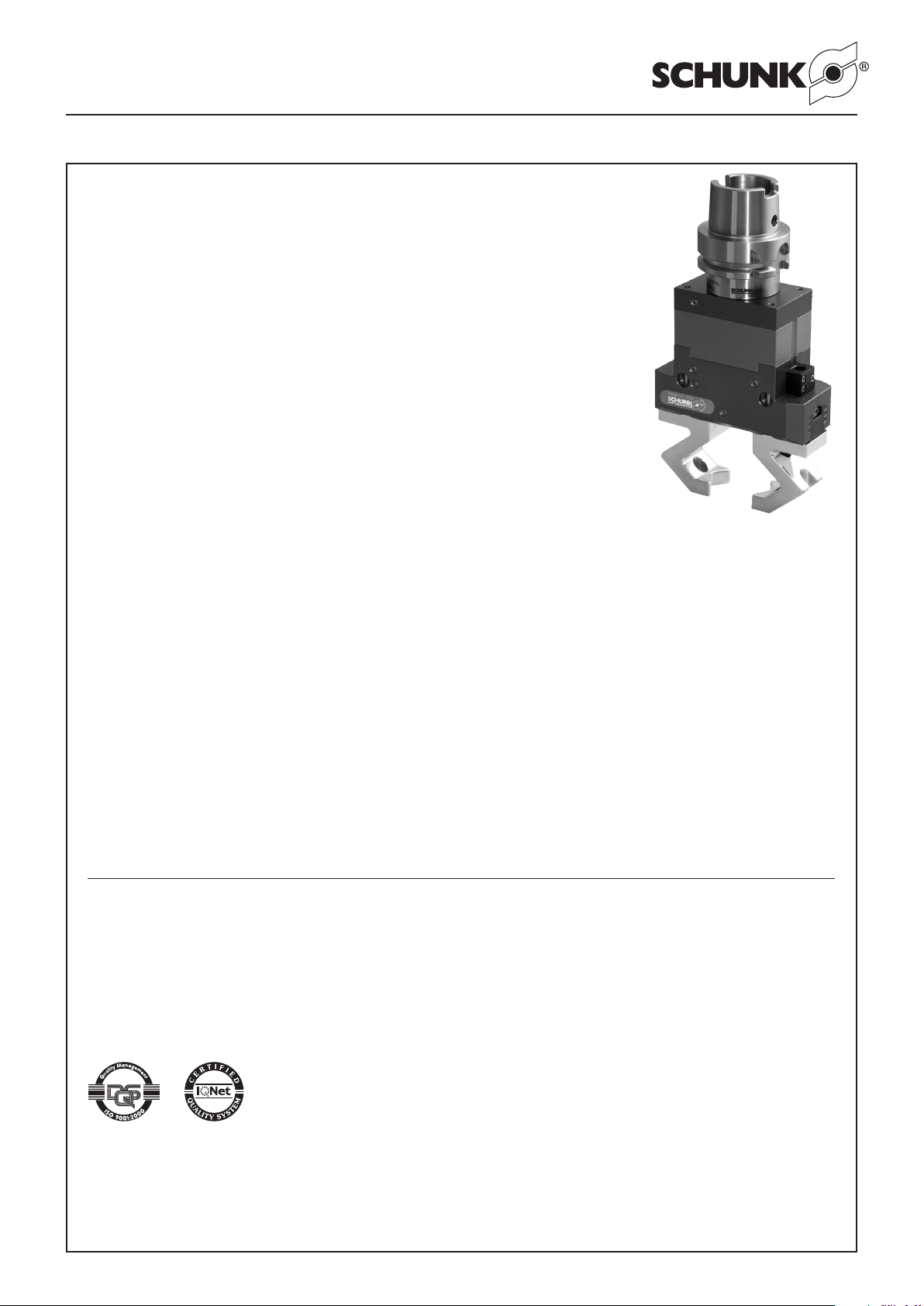
Montage- und Betriebsanleitung für 2-Backen-Parallelgreifer
SCHUNK GmbH & Co. KG
Spann- und Greiftechnik
Bahnhofstr. 106-134
74348 Lauffen/Neckar
Deutschland
Tel. +49-7133-103-0
Fax +49-7133-103 -2189
[email protected]
www.schunk.com
AUSTRIA: SCHUNK Intec GmbH
Tel. +43-7229-65770-0 · Fax +43-7229-65770-14
[email protected] · www.at.schunk.com
BELGIUM, LUXEMBOURG:
SCHUNK Intec N.V. / S. A.
Tel. +32-53-853504 · Fax +32-53-836022
[email protected] · www.be.schunk.com
CANADA: SCHUNK Intec Corp.
Tel. +1-905-712-2200 · Fax +1-905-712-2210
[email protected] · www.ca.schunk.com
CHINA: SCHUNK Representative Office
Tel. +86-21-64433177 · Fax +86-21-64431922
[email protected] · www.cn.schunk.com
CZECH REPUBLIC: SCHUNK Intec s.r.o.
Tel. +420-545229095 · Fax +420-545220508
[email protected] · www.cz.schunk.com
DENMARK: SCHUNK Intec A/S
Tel. +45-43601339 · Fax +45-43601492
[email protected] · www.dk.schunk.com
FRANCE: SCHUNK Intec SARL
Tel. +33-1-64663824 · Fax +33-1-64663823
[email protected] · www.fr.schunk.com
GREAT BRITAIN: SCHUNK Intec Ltd.
Tel. +44-1908-611127 · Fax +44-1908-615525
[email protected] · www.gb.schunk.com
RUSSIA: OOO SCHUNK Intec
Tel. +7-812-326 78 35 · Fax +7-812-326 78 38
[email protected] · www.ru.schunk.com
SLOVAKIA: SCHUNK Intec s.r.o.
Tel. +421-37-3260610 · Fax +421-37-6421906
[email protected] · www.sk.schunk.com
SOUTH KOREA: SCHUNK Intec Korea Ltd.
Tel. +82-31-7376141 · Fax +82-31-7376142
[email protected] · www.kr.schunk.com
SPAIN: SCHUNK Intec S.L.
Tel. +34-937 556 020 · Fax +34-937 908 692
[email protected] · www.es.schunk.com
SWEDEN: SCHUNK Intec AB
Tel. +46-8-554-42100 · Fax +46-8-554-42101
[email protected] · www.se.schunk.com
SWITZERLAND, LIECHTENSTEIN:
SCHUNK Intec AG
Tel. +41-523543131 · Fax +41-523543130
[email protected] · www.ch.schunk.com
TURKEY: SCHUNK Intec
Tel. +90-2163662111 · Fax +90-2163662277
[email protected] · www.tr.schunk.com
USA: SCHUNK Intec Inc.
Tel. +1-919-572-2705 · Fax +1-919-572-2818
[email protected] · www.us.schunk.com
HUNGARY: SCHUNK Intec Kft.
Tel. +36-46-50900-7 · Fax +36-46-50900-6
[email protected] · www.hu.schunk.com
INDIA: SCHUNK India Branch Office
Tel. +91-80-40538999 · Fax +91-80-41277363
[email protected] · www.in.schunk.com
ITALY: SCHUNK Intec S.r.l.
Tel. +39-031-4951311 · Fax +39-031-4951301
[email protected] · www.it.schunk.com
JAPAN: SCHUNK Intec K.K.
Tel. +81-33-7743731 · Fax +81-33-7766500
[email protected] · www.tbk-hand.co.jp
MEXICO, VENEZUELA:
SCHUNK Intec S.A. de C.V.
Tel. +52-442-223-6525 · Fax +52-442-223-7665
[email protected] · www.mx.schunk.com
NETHERLANDS: SCHUNK Intec B.V.
Tel. +31-73-6441779 · Fax +31-73-6448025
[email protected] · www.nl.schunk.com
POLAND: SCHUNK Intec Sp.zo. o.
Tel. +48-22-7262500 · Fax +48-22-7262525
[email protected] · www.pl.schunk.com
PORTUGAL: Sales Representative
Tel. +34-937-556 020 · Fax +34-937-908 692
[email protected] · www.pt.schunk.com
Reg. No. DE-003496 QM
Reg. No. DE-003496 QM
PGN-plus mit Werkzeugschnittstelle HSK/KM / Capto
Operating manual for 2-Finger Parallel Gripper
PGN-plus with tool interface HSK / KM /Capto
2-Backen-Parallelgreifer PGN-plus
mit Werkzeugschnittstelle
HSK/KM/Capto
2-Finger Parallel Gripper PGN-plus
with tool interface
HSK/KM/Capto
Sehr geehrter Kunde,
wir gratulieren zu Ihrer Entscheidung für SCHUNK. Damit
haben Sie sich für höchste Präzision, hervorragende
Qualität und besten Service entschieden.
Sie erhöhen die Prozesssicherheit in Ihrer Fertigung
und erzielen beste Bearbeitungsergebnisse – für die
Zufriedenheit Ihrer Kunden.
SCHUNK-Produkte werden Sie begeistern.
Unsere ausführlichen Montage- und Betriebshinweise
unterstützen Sie dabei.
Sie haben Fragen? Wir sind auch nach Ihrem Kauf jederzeit für Sie da. Sie erreichen uns unter den unten aufgeführten Kontaktadressen.
Mit freundlichen Grüßen
Ihre SCHUNK GmbH & Co. KG
Spann- und Greiftechnik
Dear Customer,
Congratulations on choosing a SCHUNK product. By
choosing SCHUNK, you have opted for the highest precision, top quality and best service.
You are going to increase the process reliability of
your production and achieve best machining results
– to the customer‘s complete satisfaction.
SCHUNK products are inspiring.
Our detailed assembly and operation manual will
support you.
Do you have further questions? You may contact us at
any time – even after purchase. You can reach us directly
at the below mentioned addresses.
Kindest Regards,
Your SCHUNK GmbH & Co. KG
Precision Workholding Systems
1
Druck-Nr.: 03 / PGN-plus mit HSK / de-en / 04.03.10 K
Page 2

2
Montage- und Betriebsanleitung für 2-Backen-Parallelgreifer
PGN-plus mit Werkzeugschnittstelle HSK/KM / Capto
Operating manual for 2-Finger Parallel Gripper
PGN-plus with tool interface HSK / KM /Capto
Inhaltsverzeichnis / Table of Contents
Seite / Page
1. Sicherheit / Safety 3
1.1 Symbolerklärung / Symbol key 3
1.2 Bestimmungsgemäßer Gebrauch / Appropriate use 3
1.3 Umgebungs- und Einsatzbedingungen / Environmental and operating conditions 3
1.4 Sicherheitshinweise / Safety information 3
2. Gewährleistung / Warranty 4
3. Lieferumfang / Scope of delivery 5
4. Technische Daten / Technical Data 5
5. Montage / Assembly 5
6. Energieversorgung des Greifers / Energy supply of the gripper 5
7. Wartung und Pflege des Greifers / Maintenance and care of the gripper 8
7.1 Wartungs- und Pflegeintervalle / Maintenance intervals 8
7.2 Zerlegen des Greifers / Disassembling the gripper 9
7.2.1 Version mit Greifkraftsicherung »Innensichern« / Version with “internal gripping force safety system” 10
7.3 Schraubenanzugsmomente / Screw breakaway torques 10
8. Zusammenbauzeichnung / Assembly drawing 10
9. Dichtsatz- und Ersatzteilstücklisten / Seal kit and Spare part list 12
9.1 Dichtsatzlisten / Seal kit lists 12
9.2 Beipacks / Accessories supplied 13
9.3 Ersatzteilstücklisten / Spare part lists 14
10. Montagevorrichtung / Assembly device 20
11. Zubehör / Accessories 22
11.1 Einstellsatz / Adjustment set 22
11.2 Weiteres Zubehör / Further Accessories 22
Page 3
3
Montage- und Betriebsanleitung für 2-Backen-Parallelgreifer
PGN-plus mit Werkzeugschnittstelle HSK/KM / Capto
Operating manual for 2-Finger Parallel Gripper
PGN-plus with tool interface HSK / KM /Capto
1. Safety
1.1 Symbol key
This symbol is displayed wherever there is a
danger of injury or where the gripper may suffer
damage.
1.2 Appropriate use
The unit was designed for gripping and temporary secure holding
of workpieces or other objects.
The gripper is intended for installation / mounting for machinery
and equipment. The requirements of the applicable directives
must be observed and complied with.
The gripper may only ever be employed within the restrictions of
its te
chnical specifications.
Using the system with disregard to even a minor specification will
be deemed inappropriate use. The manufacturer assumes no liability for any injury or damage resulting from inappropriate use.
1.3 Environmental and operating conditions
– Use the unit only within the application parameters defined in
the Technical Catalog. The most recent version applies
(according to the General Terms and Conditions). Please
make sure that your application has been checked based on
the current SCHUNK calculation program. If this is not the
case, we can provide no warranty.
– Standard for quality of the compressed air according to ISO
8573-1: 6 4 4.
– Clean ambient conditions at room temperature are required.
If these conditions are not ensured, the maintenance interval
will be shorter, depending on the actual utilization.
– The environment must be free of splashing water and vapors,
and also of abrasive dust and process dust. T
his does not
apply to units designed especially for dirty environments.
1.4 Safety information
1. The gripper is built according to the level of technology available at the time of delivery and is safe to operate. However,
the gripper may still be dangerous if, for example:
the gripper is used, assembled or maintained inappropriately
or is used for purposes other than those it is intended for.
the EC Machine Directive, the accident prevention regulations, the VDE guidel
ines, or the safety information and
assembly instructions are not heeded.
2. Any persons who may be responsible for assembly, commissioning and maintenance of the unit are obliged to have read
and understood all of the operating instructions, in particular
chapter 1 “Safety”. We recommend that the customer have
this confirmed in writing.
3. The installation, deinstallation, assembly of all motion detectors, connection and commissioning may only be performed
by aut
horized, appropriately trained personnel.
4. Modes of operation that adversely affect the function and/or
the operational safety of the gripper are to be refrained from.
5. Never move any parts by hand as long as the power
supply is connected.
6. Never grasp into uncovered mechanisms and never
grasp between the gripper fingers.
1. Sicherheit
1.1 Symbolerklärung
Dieses Symbol ist überall dort zu finden wo
besondere Gefahren für Personen oder Beschädigungen des Greifers möglich sind.
1.2 Bestimmungsgemäßer Gebrauch
Das Greifmodul wurde konstruiert zum Greifen und zeitbegrenzten sicheren Halten von Werkstücken bzw. Gegenständen.
Das Produkt ist zum Ein-/Anbau für Maschinen bzw. Anlagen
bestimmt. Die Anforderungen der zutreffenden Richtlinien müssen beachtet und eingehalten werd
en.
Das Produkt darf ausschließlich im Rahmen seiner technischen
Daten verwendet werden.
Ein darüberhinausgehender Gebrauch gilt als nicht bestimmungsgemäß. Für Schäden aus einem solchen Gebrauch haftet
der Hersteller nicht.
1.3 Umgebungs- und Einsatzbedingungen
– Die Einheit nur innerhalb der im Technischen Katalog defi-
nierten Einsatzparameter einsetzen. Es gilt jeweils die letzte
Fassung (lt. Kapitel 2.3 AGB). Bitte prüfen Sie, ob Ihr
Einsatzfall anhand des aktuellen SCHUNK-Berechnungsprogramms geprüft wurde. Ist dies nicht der Fall, kann keine
Gewährleistung übernommen werden.
– Anforderung an die Druckluftqualität nach ISO 8573-1: 6 4 4.
– Vorraussetzung sind saubere Umgebungsbedingungen bei
Raumtemperatur. Sollte dies nicht eingehalten werden, ver-
ringert sich je nach Anwendungsfall das Wartungsintervall.
– Die Umgebung muss frei von Spritzwasser und Dämpfen,
sowie von Abriebs- oder Prozessstäuben se
in. Ausgenommen hiervon sind Einheiten, die speziell für verschmutzte
Umgebungen ausgelegt sind.
1.4 Sicherheitshinweise
1. Der Greifer ist nach dem Stand der Technik zum Zeitpunkt
der Auslieferung gebaut und betriebssicher. Gefahren können von ihm jedoch ausgehen, wenn z.B.:
der Greifer unsachgemäß eingesetzt, montiert, gewartet oder
zum nicht bestimmungsgemäßen Gebrauch eingesetzt wird.
die EG-Maschinenrichtlinie, die UVV, die VDE-Richtlinien, die
Si
cherheits- und Montagehinweise nicht beachtet werden.
2. Jeder, der für die Montage, Inbetriebnahme und Instandhaltung zuständig ist, muss die komplette Betriebsanleitung,
besonders das Kapitel 1 »Sicherheit«, gelesen und verstanden haben. Dem Kunden wird empfohlen, sich dies
schriftlich bestätigen zu lassen.
3. Der Ein- und Ausbau, die Montage der Näherungsschalter,
das Anschließen und die Inbetriebnahme darf nur von autorisiertem Personal durchgeführ
t werden.
4. Arbeitsweisen, die die Funktion und Betriebssicherheit des
Greifers beeinträchtigen, sind zu unterlassen.
5. Keine Teile von Hand bewegen, wenn die Energieversorgung angeschlossen ist.
6. Nicht in die offene Mechanik und zwischen die
Greiferfinger greifen.
Page 4
4
Montage- und Betriebsanleitung für 2-Backen-Parallelgreifer
PGN-plus mit Werkzeugschnittstelle HSK/KM / Capto
Operating manual for 2-Finger Parallel Gripper
PGN-plus with tool interface HSK / KM /Capto
7. Bei Montage-, Umbau-, Wartungs- und Einstellarbeiten sind die Energiezuführungen zu entfernen.
8. Wartung, Um- oder Anbauten außerhalb der Gefahrenzone durchführen.
9. Bei Ein- und Ausbau, Montage, Anschließen, Einstellen, Inbetriebnehmen und Testen muss sichergestellt sein, dass ein versehentliches Betätigen der
Einheit durch den Monteur oder andere Personen
ausgeschlossen ist.
10. Beim Einsatz aller Handhabungsmodule müssen
Schutzabdeckungen gemäß EG-Maschinenrichtlinie
Punkt 1.4 vorgesehen werden.
11. Es bestehen Gefahren durch herabfallende und
herausgeschleuderte Gegenstände. Treffen Sie Vorkehrungen, um das Herabfallen oder das Herausschleudern von eventuell gefährlichen Gegenständen (bearbeitete Werkstücke, Werkzeuge,
Späne, Bruchstücke, Abfälle usw.) zu vermeiden.
12. Greifer die mit Federkraft spannen oder eine
Greifkrafterhaltung mit Federn besitzen stehen unter
Federspannung. Beim Zerlegen einer solchen
Einheit ist daher besondere Vorsicht geboten.
13. Greifer mit einer mechanischen Greifkrafterhaltung
können sich bei einem »Not-Aus« noch eigenständig in die durch die mechanische Greifkrafterhaltung
vorgegebene Richtung bewegen. Die Endpositionen
des Greifers können mit SCHUNK SDV-P Ventilen
bei »Not-Aus« gehalten werden.
14. Die Aufsatzbacken müssen, insbesondere bei
Greifern mit mechanischer Greifkrafterhaltung so
ausgeführt werden, dass der Greifer im drucklosen
Zustand eine der Endlagen offen oder geschlossen
erreicht und somit bei einem Wechsel der Aufsatzbacken keine Restenergie freigesetzt werden kann.
15. Zusätzliche Bohrungen, Gewinde oder Anbauten, die nicht
als Zubehör von SCHUNK angeboten werden, dürfen nur mit
Genehmigung der Fa. SCHUNK angebracht werden.
16. Darüber hinaus gelten die am Einsatzort gültigen Sicherheitsund Unfallverhütungsvorschriften.
2. Gewährleistung
Die Gewährleistung beträgt 24 Monate ab Lieferdatum Werk bei
bestimmungsgemäßem Gebrauch im 1-Schicht Betrieb und unter
Beachtung der vorgeschriebenen Wartungs- und Schmierintervalle und der definierten Umgebungs- und Einsatzbedingungen (siehe Kapitel 1.3).
Grundsätzlich sind werkstücksberührende Teile und Verschleißteile nicht Bestandteil der Gewährleistung. Verschleißteile sind im
Kapitel Dichtsatz- und Ersatzteilstücklisten als solche gekennzeichnet. Beachten Sie hierzu auch unsere Allgemeinen
Geschäftsbedingungen (AGB). Diese finden Sie auf unserer
Webseite www.de.schunk.com unter »Service« bei den
»Verkaufs- un
d Lieferbedingungen«.
Die Einheit gilt dann als defekt, wenn deren Grundfunktion
Greifen oder Schwenken nicht mehr gegeben ist.
7. Always disconnect the power supply lines during
assembly, conversion, maintenance and setting work.
8. Always carry out maintenance work, conversions and
attachments outside of the danger zone.
9. During assembly, connection, setting, commissioning
and testing, it is imperative to exclude the possibility
that the fitter or any other person could accidentally
activate the unit.
10. When using handling modules, protective covers
must be used according to EC Machine Directive,
Point 1.4.
11. There is a danger of injury and a risk of damages due
to falling and catapulted components. Precautions
must be taken to prevent any potentially dangerous
objects (processed workpieces, tools, chips, debris,
waste etc.) from falling or being catapulted out of the
unit.
12. Grippers that clamp using spring force or that are
equipped with spring gripping force maintenance are
subject to spring tension. Therefore, special care
must be taken when dismantling such units.
13. Grippers equipped with mechanical gripping force
maintenance may continue to move into the position
indicated by the mechanical gripping force maintenance independently even after an “emergency
stop”. If SCHUNK SDV-P valves are used, the final
position of a gripper after an “emergency stop” can
be kept.
14. Top jaws, especially those used for grippers with
mechanic gripping force safety device, have to be
designed in a way, that the gripper reaches one of its
end-positions, "open" or "closed", when no pressure
is applied. This prevents the release of any residual
engergy during the change of the top jaws.
15. Additional holes, threads or attachments which are not supplied as accessories by SCHUNK may only be applied after
obtaining the prior consent of SCHUNK.
16. Above and beyond that, the safety and accident prevention
regulations in force at the location of use apply.
2. Warranty
The warranty period is 24 months from the date of delivery when
utilized as intended in single-shift operations and in compliance
with the specified maintenance and lubrication intervals and
the defined environmental and operating conditions (see
Chapter 1.3).
Parts that come into contact with the workpiece and wearing parts
are not covered by the warranty. Wearing parts are designated
accordingly in the Seal kit and spare parts lists.
See also our General Terms and Conditions in this regard.
The unit is considered defective when the basic gripping or rota-
ry function is inoperable.
Page 5
5
Montage- und Betriebsanleitung für 2-Backen-Parallelgreifer
PGN-plus mit Werkzeugschnittstelle HSK/KM / Capto
Operating manual for 2-Finger Parallel Gripper
PGN-plus with tool interface HSK / KM /Capto
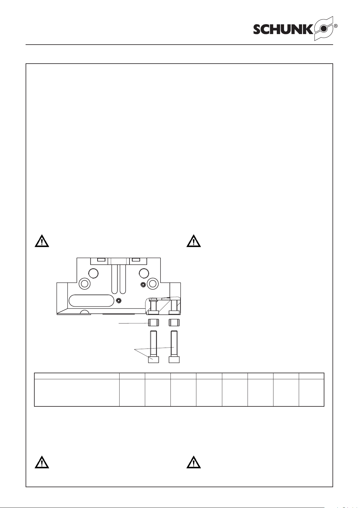
Pos. 19/20
Fingerfixierung
Finger fixing
Fingerbefestigung
Finger fastening
3. Lieferumfang
Greifeinheit bestehend aus:
– PGN-plus
– HSK/ KM/Capto-Werkzeugschnittstelle
– Adapterplatte mit integrierten Druckteiler
– Beipack
4. Technische Daten
Die technischen Daten entnehmen Sie bitte dem aktuellen Katalog
und der Bedienungsanleitung des entsprechenden Greifers.
– Der von dem Greifer ausgehende Luftschall ist kleiner als
70 dB (A)
– Der maximale Arbeitsdruck beträgt 8 bar.
Der empfohlene Arbeitsdruck beträgt 6 bar – wie unter
Kapitel 5 »Einstellung des internen Effektivdruckes«
be schrieben.
5. Montage
Achtung!
Bei der Montage des Greifers muss die Energieversorgung abgeschaltet sein. Beachten Sie auch die
Sicherheits hinweise auf den Seiten 3 und 4.
3. Scope of delivery
Gripper unit consisting of:
– PGN-plus
– HSK/ KM/Capto tool interface
– Adapter plate with integrated distribution of compressed air
– Accessories
4. Technical Data
For technical data, please refer to the current catalogue and the
operating manual of the corresponding gripper.
– The airborne noise emitted by the gripper is lower than
70 dB (A)
– The maximum operation pressure is 8 bar.
The recommended operating pressure is 6 bar – see
description of chapter 5 “adjustment of the internal effective
pressure”.
5. Assembly
cAutIOn!
Before starting assembly of the gripper, the power
supply must be switched off. Please also consider
the safety hints on pages 3 and 4.
Die zur Greiferfinger befesti gung benötigten Zentrierhülsen sind in dem jeweiligen Beipack enthalten.
The guide sleeves required for fastening the gripperfinger are contained in the relevant enclosed pack.
Type PGN+50 PGN+64 PGN+80 PGN+100 PGN+125 PGN+160 PGN+200 PGN+300
Gewindedurchmesser und max. M3 M4 M5 M6 M6 M10 M12 M16
Einschraubtiefe bei Fingerbefestigung
Thread Ø and max. insertion depth 8 10 10 13 13 17 17 17
for finger fastening tief / deep tief / deep tief / deep tief / deep tief / deep tief / deep tief / deep tief / deep
6. Energieversorgung des Greifers
Bitte lesen Sie den nachfolgenden Abschnitt sehr
sorgfältig, ansonsten kann es leicht zur Zerstörung
des Greifers führen und vom Greifer eine nicht zu
unterschätzende Gefahr ausgehen.
6. Energy supply of the gripper
Thoroughly peruse the folloing chapter, since the
gripper can be easily damaged and the gripper can
be an undervalued danger for its surrounding.
Page 6
6
Montage- und Betriebsanleitung für 2-Backen-Parallelgreifer
PGN-plus mit Werkzeugschnittstelle HSK/KM / Capto
Operating manual for 2-Finger Parallel Gripper
PGN-plus with tool interface HSK / KM /Capto
Allgemeines:
Der HSK/ KM/Capto-Greifer kann bis zu einem externen
Mediendruck von 60 bar betrieben werden.
Die nachfolgend beschriebene Einstellung des effektiven,
internen Greiferdrucks muss immer bei der Inbetriebnahme
in einer anderen Werkzeugmaschine durchgeführt werden.
Regelmäßig, mindestens 1 Mal pro Woche, ist die Einstellung zu
überprüfen!
Die Einstellung muss mit dem SCHUNK-Einstellsatz (Ident-Nr.:
308599) oder einem gleichwertigen Gerät erfolgen.
Arbeiten an der Werkzeugspindel sind bei den meisten Werk-
zeugmaschinen nur bei geschlossener Sicherheitstüre möglich.
Halten Sie stets die Sicherheitsvorschriften gem. der Anleitung
Ihrer Werkzeugmaschine ein. Eventuell ändert sich der unten
beschriebene Ablauf aufgrund Ihrer Werkzeugmaschine leicht ab.
Einstellung des internen Effektivdruckes:
1. Vergewissern Sie sich, dass die seitliche Drossel
(mit Abspritzschlauch) komplett geöffnet ist.
Ansonsten drehen Sie die Einstellschraube
komplett heraus!
2. Stellen Sie die Richtung des Abspritzschlauches so ein, dass
das daraus herausspritzende Kühlschmiermittel in einen
unkritischen Bereich spritzt. Dies ist meist in Richtung einer
hinteren Ecke des Bearbeitungsraumes. Achten Sie darauf,
dass das Adapterstück der Drossel in der Adapterplatte fest
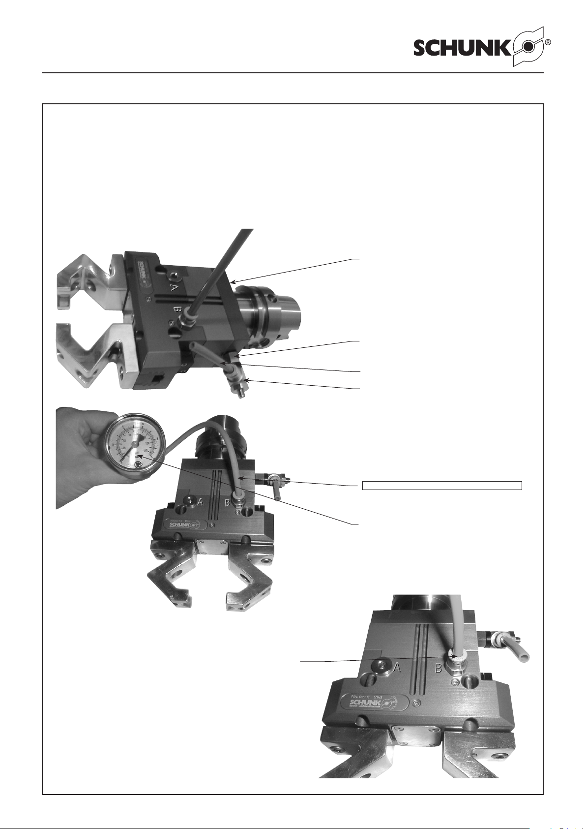
verschraubt und damit dicht bleibt! (siehe Bild 1)
3. Lösen Sie die Verschlussschraube am Anschluss B (bei
Innengreifen, also der Bezeichnung “..... IS” am Greifer)
bzw. Anschluss A (bei Außengreifen, also der Bezeichung
“..... AS” am Greifer), enfernen Sie die Schraube und instal-
lieren Sie den Einstellsatz (siehe Bild 2 und 3 auf Seite 7).
4. Wechseln Sie den HSK / KM / Capto-Greifer in die Werkzeugmaschine ein. Dies geht am einfachsten durch manuelles
Einwechseln.
5. Schalten Sie die Innenkühlschmiermittelzufuhr ein.
Aus dem Abpritzschlauch spritzt Kühlschmiermittel
und das Manometer zeigt deutlich weniger als 6 bar
an (meist ca. 2 bar). Ansonsten sofort abbrechen!
und weiter bei Punkt F1.
F1: Lösen Sie zuerst den Greifer von der Adapterplatte,
anschließend die Adapterplatte von der HSK/KM / Capto Werkzeugaufnahme. In der Mitte der Adapterplatte befindet sich, eingeschraubt in einem M5 Gewinde, eine Düse mit Ø 1.0. Entfernen
Sie diese und ersetzen Sie sie durch die mitgelieferte Düse Ø 0.7
(Beipack). Montieren Sie nun die Komponenten in umgekehrter
Reihenfolge wieder zusammen.
Die Drossel wieder komplett öffnen (heraus drehen).
Sollte der Anfangsdruck jedoch wieder nicht kleiner als 6 bar sein,
brechen Sie den Vorgang ab. Ihre Werkzeugmaschine ist zum
Einsatz unseres HSK/KM/Capto-Greifers nicht geeignet. Setzen
Sie sich bitte mit Fa. SCHUNK in Verbindung.
Sollte der angezeigte Druck nun kleiner sein als 6 bar, dann
weiter bei Punkt 6.
6. Drehen Sie die Drossel langsam zu. Der Druck, der am
Manometer des Einstellsatzes abzulesen ist, beginnt langsam
anzusteigen. Stellen Sie einen Druck von 6 bar ein.
7. Schalten Sie die Kühlschmiermittelzufuhr aus.
General information:
The HSK/KM / Capto-Gripper can be actuated up to an external
pressure of 60 bars.
The following described adjustment of the effective, internal
gripper pressure has to be done for first operation on an
other tooling machine.
This adjustment has to be checked regularly, at least once a
week!
The adjustment has to be made with a SCHUNK adjustment set
(Id.-No. 308599) or with any equivalent device.
Most of the tooling machines only allow works at the tool spindle
if the safety doors are closed. Please always respect the safety
instructions in accordance to the operation manual of your tooling
machine. It may happen, that the described operation routine
may change due to tooling machine used.
Adjustment of the internal effective pressure:
1. Make sure that the lateral throttle (the one with
the hose) is completely open. If not, turn out the
adjustment screw completely!
2. Adjust the direction of the hose in a way that the escaping
coolant is directed into a non-critical area. Mostly this will be
into the direction of a rear corner of the machining area. Make
sure that the adapter piece of the throttle is firmly screwed
onto the adapter plate so that everything keeps tight! (see
illustration 1)
3. Loosen the sealing screw at connection B (if ID gripping,
that means grippers with label “......IS” in that case) or at
connection A (if OD gripping, that means grippers with
label “......AS” in that case), remove the screw and install the
adjustment set (see illustration 2 and 3 on page 7).
4. Insert the HSK /KM/Capto-gripper in the tooling machine. The
easiest way will be to insert it manually.
5. Switch on the internal coolant supply. Coolant
will escape from the hose and the pressure gauge
shows a considerably lower value than 6 bar
(Usually appr. 2 bar) otherwise stop this procedure
immediately! and continue with point F1.
F1: Loosen the gripper from the adapter plate first, then the
adapter plate from the HSK/ KM /Capto tool mounting. In the
centre of the adapter plate you will find an M5 thread, in which
a nozzle of Ø 1.0 is screwed in. Remove it and replace it by the
supplied nozzle of Ø 0.7. Assembly of the components is done in
reverse order now.
The throttle has to be opened completely again (turn it out).
If the starting pressure however, shouldn‘t be lower than 6 bar
again, stop this procedure. Your tooling machine is not suitable
for the use of our HSK/KM/Capto-gripper. Please get in contact
with the SCHUNK technicians.
If the shown pressure is lower than 6 bar, please continue with
point 6.
6. Slowly close the throttle. The pressure indicated at the pressure
gauge of the adjustment set begins to increase slowly. Adjust
a pressure of 6 bar.
7. Turn off the cooling supply.
Page 7
7
Montage- und Betriebsanleitung für 2-Backen-Parallelgreifer
PGN-plus mit Werkzeugschnittstelle HSK/KM / Capto
Operating manual for 2-Finger Parallel Gripper
PGN-plus with tool interface HSK / KM /Capto
8. Entfernen Sie den Einstellsatz und verschließen Sie den
Anschluss B wieder mit der Verschlussschraube.
9. Der HSK / KM / Capto-Greifer ist nun auf diese Maschine
(diesen Kühl schmiermitteldruck und diesen Volumenstrom)
eingestellt.
10. Der Greifer kann nun als normales Werkzeug ein- und
ausgewechselt werden. Das Schließen des Greifers erfolgt
nun über den Maschinenbefehl »Innenkühlschmiermittel an«,
das Öffnen durch den Befehl »Innenkühlschmiermittel aus«.
Bild 1 / Illustration 1
8. Remove the adjustment set and close the connection B again
with the sealing screw.
9. The HSK/KM/Capto-gripper is adjusted to this machine (this
coolant pressure and this volume current).
10. The gripper can be now exchanged like any conventional
tool. Closing of the gripper is done by the machine command
“Internal coolant on”, opening by the command “internal
coolant off”.
Adapterplatte / Adapter plate
Adapterstück für Drossel /
Adapter piece for throttle
Abspritzschlauch / Hose
Drossel / Throttle
Bild 2 / Illustration 2
Einstellsatz / Adjustment set
Manometer / Pressure gauge
Bild 3 / Illustration 3
Anschluss des Einstellsatzes
Connection of the adjustment set
Page 8

8
Montage- und Betriebsanleitung für 2-Backen-Parallelgreifer
PGN-plus mit Werkzeugschnittstelle HSK/KM / Capto
Operating manual for 2-Finger Parallel Gripper
PGN-plus with tool interface HSK / KM /Capto
7. Wartung und Pflege des Greifers
Beachten Sie unbedingt die Sicherheitshinweise auf
den Seiten 3 und 4.
7.1 Wartungs- und Pflegeintervalle
PGN-plus mit Werkzeugschnittstelle HSK / KM / Capto
Wartungsintervalle (Mio. Zyklen)
Umgebungstemperaturen über 60 ° C führen zu schnellerem
Aus härten, vereinzelte Kühlschmierstoffe und Flüssigkeiten
führen teilweise zum schnelleren Auswaschen der eingesetzten
Schmierstoffe. Schmier- und Wartungs arbeiten dementsprechend
häufiger durchführen oder den Greifer gegebenenfalls gegenüber
diesen Umgebungseinflüssen schützen.
Hinweise
Die Grundbacken und die Führungen im Gehäuse sind zueinander
abgestimmt. Zum Austausch dieser Teile schicken Sie den Greifer
komplett mit einem Reparaturauftrag an Fa. SCHUNK.
Um die Funktion des Greifers zu erhalten, beachten Sie bitte
folgende Hinweise:
1. Druckmittel: Druckluft
Anforderung an die Druckluftqualität nach ISO 8573-1: 6 4 4.
Alternativ verwendetes Kühlschmiermittel muss gefiltert sein
(30 µm).
2. Blanke, außenliegende Stahlteile müssen geölt oder gefettet
werden.
3. Bei der Wartung sind bestimmte Teile mit Öl bzw. Fett zu
montieren (Grundfettung):
a) Alle metallischen Gleitflächen müssen mit LINO MAX oder
einem gleichwertigen Schmierstoff behandelt werden.
b) Die Kolbenbohrung sowie alle Dichtungen werden mit
Renolit HTL 2 oder einem gleichwertigen Schmierstoff
behandelt.
4. Bei jeder Wartung des Greifers sind alle Dichtungen zu
erneuern (siehe Dichtsatzlisten, Kapitel 9.1). Der komplette
Dichtsatz ist bei SCHUNK erhältlich.
5. Soweit nicht anders vorgeschrieben sind alle Schrauben
und Muttern mit Loctite Nr. 243 zu sichern und mit einem
Anzugsmoment gemäß DIN anzuziehen. (Siehe auch
Kapitel 7.3
6. Zusätzlich zu den oben beschriebenen Wartungen können die
Führungen des Greifers, anstelle des Sperrluftanschlusses,
je nach Belastung, über Schmiernippeln mit LINO MAX oder
einem gleichwertigen Schmierstoff nachgeschmiert werden.
Entfernen Sie hierzu die beiden Gewindestifte für den
Sperrluftanschluss (Pos. 48) und ersetzen Sie diese durch 2
Schmiernippel mit Anschlussgewinde M5.
2
7.
Maintenance and care of the gripper
It is essential to read and observe the safety
instructions on pages 3 and 4.
7.1 Maintenance intervals
PGN-plus with tool interface HSK / KM / Capto
Maintenance intervals (million cycles)
Environmental temperatures of more than 60°C / 140°F can
lead to a faster hardening. Some coolants and lubricants accelerate the washing out of used lubricants. Therefore, lubrication
and maintenance works have to be carried out more often, or if
necessary, the gripper has to be protected against environmental
influences.
2
Notes
The base jaws in the housing are matched to one another. In
order to replace these components, please return the gripper to
SCHUNK for repairs.
In order to ensure that the gripper continues to function properly,
please read and observe the following instructions:
1. Pressure medium: compressed air
Standard for quality of the compressed air according to ISO
8573-1: 6 4 4.
Alternatively used coolant must be filtered (30 µm).
2. All external blank steel components must be oiled or greased.
3. When carrying out a service, certain parts must be oiled or
greased before fitting (permanent lubrication):
a) All metallic sliding surfaces must be treated with LINO MAX
or a similar lubricant.
b) The piston bore and all seals must be treated with Renolit
HLT 2 or a similar lubricant.
4. The seals must be replaced each time the gripper is serviced
(see seal kit list, chapter 9.1). The full seal kit is available from
SCHUNK.
5. Unless otherwise specified, all screws and nuts must be
secured with Loctite No. 243 and tightened with a starting
torque in accordance with DIN. (See also chapter 7.3)
6. In addition to the maintenance work described above, the
gripper guides may be re-lubricated with LINO MAX or a similar
lubricant through the lubricating nipple.
To do this, remove the two set screws for the air purge
connection (Item 48) and replace them with 2 lubricating
nipples using an M5 connection thread.
Page 9
9
Montage- und Betriebsanleitung für 2-Backen-Parallelgreifer
PGN-plus mit Werkzeugschnittstelle HSK/KM / Capto
Operating manual for 2-Finger Parallel Gripper
PGN-plus with tool interface HSK / KM /Capto
7.2 Zerlegen des Greifers
Der Zusammenbau erfolgt in umgekehrter Reihenfolge. Beachten
Sie dabei die Kapitel 7.1 und die Schraubenanzugsmomente
Kapitel 7.3.
1. Entfernen Sie die Druckluftleitungen.
2. Drehen Sie die Schrauben (Pos. 47) heraus und entfernen Sie
dann das Abdeckblech (Pos. 5).
3. Markieren Sie die Einbaulage des Kolbens (Pos. 3/8) und der
Grundbacken (Pos. 2/7) im Gehäuse.
Achtung!
Im Falle eines Defektes kann der Deckel (Pos. 9) unter
Federspannung stehen.
4. Spannen Sie den Greifer zwischen den Grundbacken
(Pos. 2/7) und dem Deckel (Pos. 9) so in den Schraubstock
ein, dass Sie die 4 Schrauben (Pos. 46) noch entfernen
können. Drehen Sie die Schrauben (Pos. 46) heraus. Öffnen
Sie danach den Schraubstock vorsichtig und entfernen Sie den
Deckel (Pos. 9). Anschließend entfernen Sie die Zentrierhülsen
(Pos. 19).
Achtung!
Bei der Version »Außensichern« steht der Zylinderkolben (Pos. 10) unter Federspannung.
5. Spannen Sie den Greifer vorsichtig zwischen Grundbacken
(Pos. 2/7) und Zylinderkolben (Pos. 10) ein. Drehen Sie
die Schraube (Pos. 45) heraus und entspannen Sie dann
den Schraubstock vorsichtig, bis die Druckfeder entspannt
ist. Entfernen Sie den Zylinderkolben (Pos. 10) und den
Distanzbolzen (Pos. 11 – ab Baugröße 125) aus dem Gehäuse
(Pos. 1).
6. Drücken Sie den Kolben (Pos. 3/8) nach oben aus dem
Gehäuse (Pos. 1) heraus.
7. Ziehen Sie die Grundbacken (Pos. 2/7) aus dem Gehäuse
(Pos. 1) heraus.
8. Reinigen Sie alle Teile gründlich und kontrollieren Sie alle
Teile auf Defekt und Verschleiß.
9. Erneuern Sie alle Dichtungen (siehe Dichtsatzliste, Kapitel
9.1).
Die Montage der Baugröße 125 – 200 erfolgt in umgekehrter
Reihenfolge. Beachten Sie dabei die Kapitel 7.1 und die
Schraubenanzugsmomente Kapitel 7.3.
Achtung!
Bei der Version »Aussensichern« Baugröße 64 – 100
muss der Kolben mit Hilfe einer Montagevorrichtung
montiert werden.
(Pos.-Nr. siehe Kapitel 8 »Zusammenbauzeichnungen«)
Zeichnungen und Maße der Montagevorrichtung siehe Kapitel 9
1. Grundbacken (Pos. 2/7) und Kolben (Pos. 3/8) im Gehäuse
(Pos. 1) montieren. Legen Sie danach den Zylinderkolben
(Pos. 10) mit Dichtungen (Pos. 30/33) und Druckfeder
(Pos. 25) in das Gehäuse ein.
2. Vorrichtung vorsichtig über den Zylinderkolben stülpen und mit
den Schrauben 1 auf dem Gehäuse montieren.
3. Schraube (Pos. 45) einlegen und mit dem geforderten
Drehmoment anziehen (siehe Kapitel 7.3).
4. Entfernen Sie die Vorrichtung und montieren Sie den Greifer
weiter in umgekehrter Reihenfolge wie beim Zerlegen. Beachten
Sie dabei die Kapitel 7.1 und die Schraubenanzugsmomente
Kapitel 7.3.
7.2 Disassembling the gripper
Carry out assembly in the reverse order from the above. When
reassembling, observe the instructions in chapter 7.1 and the
screw breakaway torque in chapter 7.3.
1. Remove the compressed air lines.
2. Undo the screws (Item 47) and then remove the cover plate
(Item 5).
3. Mark the position of the piston (Item 3/8) and the base jaws
(Item 2/7) in the housing.
cAutIOn!
In the event of a defect, the cover (Item 9) may be
spring-loaded.
4. Clamp the gripper into the vice between the base jaws
(Item 2/7) and the cover (Item 9) in such a way as to be able
to remove the 4 screws (Item 46). Undo the screws (Item 46).
Then open the vice carefully and remove the cover (Item 9).
Then remove the guide sleeves (Item 19).
cAutIOn!
In the case of the version with the ”external safety
system“, the cylinder piston (Item 10) is springloaded.
5. Carefully clamp the gripper between the base jaws
(Item 2/7) and the cylinder piston (Item 10). Undo the screw
(Item 45) and then carefully open the vice until the tension
on the compression spring is released. Remove the cylinder
piston (Item 10) and the distance bolt (Item 11 – from size 125)
and the springs (Item 25) from the housing (Item 1).
6. Press the piston (Item 3/8) upwards out of the housing
(Item 1).
7. Pull the base jaws (Item 2/7) out of the housing (Item 1).
8. Clean all parts thoroughly and check them for any defects or
wear and tear.
9. Replace all the seals (see seal kit list, chapter 9.1).
For sizes 125 – 200, the unit is reassembled in the reverse order
from the above. When reassembling, observe the instructions in
chapter 7.1 and the screw breakaway torque in chapter 7.3.
cAutIOn!
In the case of sizes 64 –100, in the version with
the ”external safety system“, the piston must be
assembled with the aid of an assembly device.
(For Item no., see chapter 8, ”Assembly drawing“)
For drawings and the dimensions of the assembly device, see
chapter 9.
1. Fit the base jaws (Item 2/7) and the piston (Item 3/8) in the
housing (Item 1). Then fit the cylinder piston (Item 10) with
seals (Item 30/33) and compression springs (Item 25) in the
housing.
2. Carefully slip the device over the cylinder piston and fit to the
housing with the screws.
3. Insert the screw (Item 45) and tighten to the required torque
(see chapter 6.3).
4. Remove the device and continue to assemble the gripper
in the reverse order to the order for disassembling. When
reassembling, observe the instructions in chapter 7.1 and the
screw breakaway torque in chapter 7.3.
Page 10
10
Montage- und Betriebsanleitung für 2-Backen-Parallelgreifer
PGN-plus mit Werkzeugschnittstelle HSK/KM / Capto
Operating manual for 2-Finger Parallel Gripper
PGN-plus with tool interface HSK / KM /Capto
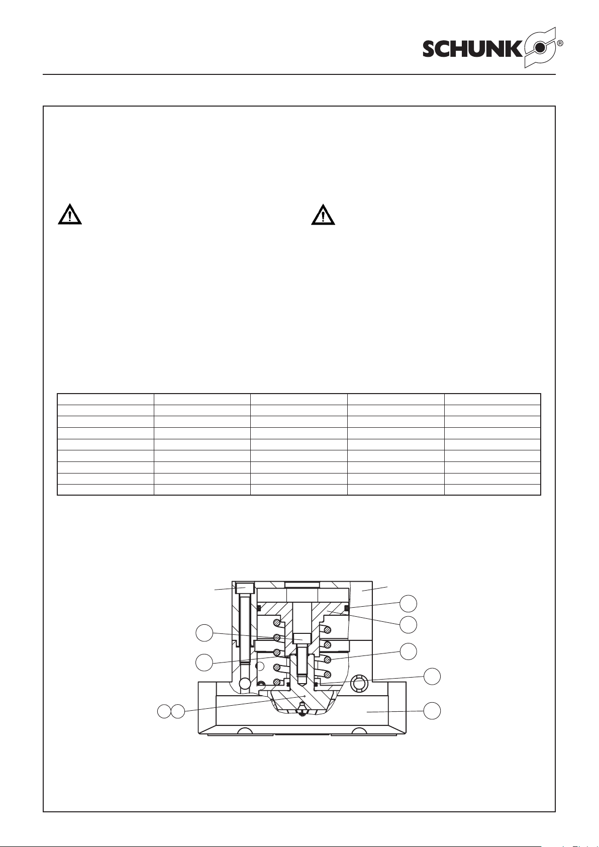
8
50
33
30
Schraube / Screw
25
Vorrichtung / Device
3
45
31
10
1. Entfernen Sie die Druckluftleitungen.
2. Drehen Sie die Schrauben (Pos. 47) heraus und entfernen Sie
dann das Abdeckblech (Pos. 5).
3. Markieren Sie die Einbaulage des Kolbens (Pos. 3/ 8) und der
Grundbacken im Gehäuse (Pos. 2/7).
Achtung!
4. Spannen Sie den Greifer zwischen den Grundbacken
(Pos. 2/7) und dem Deckel (Pos. 9) so in den Schraubstock
ein, dass Sie die 4 Schrauben (Pos. 46) noch entfernen
können. Drehen Sie die Schrauben (Pos. 46) heraus. Danach
entspannen Sie den Schraubstock vorsichtig bis die Druckfeder
entspannt ist. Nehmen Sie den Deckel und die Druckfeder ab.
Fahren Sie fort wie beim Greifer ohne Greifkraftsicherung (von
Punkt 5 bis 9).
Der Zusammenbau erfolgt in umgekehrter Reihenfolge. Beachten
Sie dabei die Kapitel 7.1 und die Schraubenanzugsmomente
Kapitel 7.3.
7.2.1 Version with ”Internal gripping force safety system“
1. Remove the compressed air lines.
2. Undo the screws (Item 47) and then remove the cover plate
(Item 5).
3. Mark the position of the piston (Item 3/8) and the base jaws
(Item 2/7) in the housing.
cAutIOn!
In the case of the version with the ”internal safety
system“, the cover (Item 9) is spring-loaded.
4. Clamp the gripper into the vice between the base jaws
(Item 2/7) and the cover (Item 9) in such a way as to be able
to remove the 4 screws (Item 46). Fully undo the screws (Item
46). Then open the vice carefully until the tension on the
compression spring (Item 25) is released. Remove the cover
and the compression spring.
Continue as in the case of the gripper without gripping force safety
system (from paragraphs 5 to 9).
Carry out assembly in the reverse order from the above. When
reassembling, observe the instructions in chapter 7.1 and the
screw breakaway torque in chapter 7.3.
7.3 Screw breakaway torques
Type Pos. / item 40 Pos. / item 41 Pos. / item 45 Pos. / item 46
PGN-plus 50 0.8 Nm 1.3 Nm 2.2 Nm 1.3 Nm
PGN-plus 64 6 Nm 1.3 Nm 10 Nm 1.3 Nm
PGN-plus 80 10 Nm 3 Nm 17 Nm 3 Nm
PGN-plus 100 17 Nm 3 Nm 17 Nm 3 Nm
PGN-plus 125 24 Nm 6 Nm 41 Nm 6 Nm
PGN-plus 160 48 Nm 6 Nm 83 Nm 6 Nm
PGN-plus 200 75 Nm 6 Nm 116 Nm 25 Nm
PGN-plus 300 120 Nm 6 Nm 150 Nm 25 Nm
8. Zusammenbauzeichnungen 8. Assembly drawings
Page 11
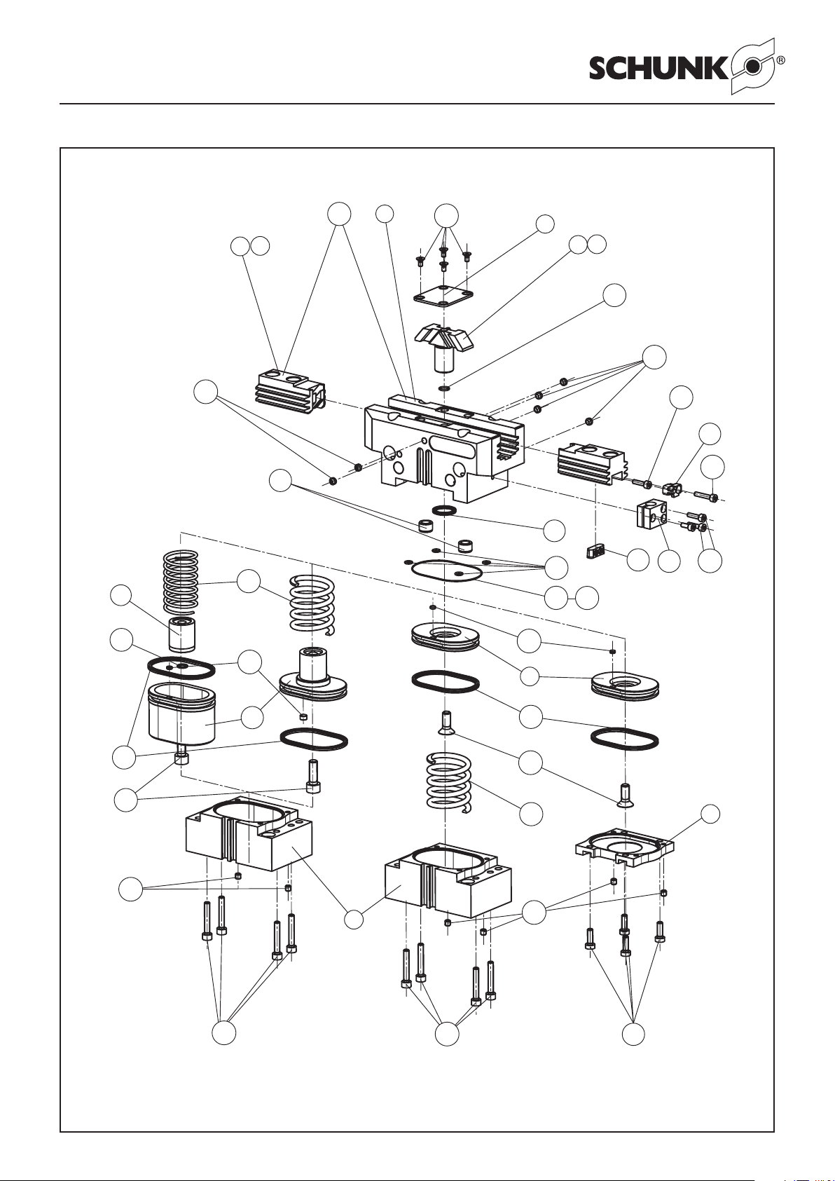
11
Montage- und Betriebsanleitung für 2-Backen-Parallelgreifer
PGN-plus mit Werkzeugschnittstelle HSK/KM / Capto
Operating manual for 2-Finger Parallel Gripper
PGN-plus with tool interface HSK / KM /Capto
nicht bei Version ohne
Greifkraftsicherung
Not for version without
gripping force saftey device
32
*
Diese Teile sind im Dichtsatz vorhanden und können nur komplett bestellt werden.
*
These parts are available in the seal kit list and can only be ordered as a unit.
PGN-plus 125 – 200
PGN-plus 64 – 100
nicht bei
not for
PGN-plus 64
Pos. 12 bei / for
PGN-plus 64 – 80
*
1
6
11
60
17
34
25
16
31
44
42
15
19
50
48
43
48
33
8
3
5
47
7
2
*
*
*
*
12
*
*
*
25
40
30
49
9
46
49
45
30
10
60
33
4
41
46
Version Außensichern
Version with safety device
O.D. gripping
Version Innensichern
Version with safety device
I.D. gripping
Version ohne
Greifkraftsicherung
Version without gripping
force safety device
Page 12
12
Montage- und Betriebsanleitung für 2-Backen-Parallelgreifer
PGN-plus mit Werkzeugschnittstelle HSK/KM / Capto
Operating manual for 2-Finger Parallel Gripper
PGN-plus with tool interface HSK / KM /Capto
9.
Dichtsatz- und Ersatzteilstücklisten
9. Seal kit and spare parts lists
9.1 Dichtsatzlisten
9.1 Seal kit lists
Dichtsatzliste PGN-plus 50 Ident-Nr. 370 891 Seal kit list PGN-plus 50 Id. No. 370 891
Pos. / item Ident-Nr. / Id. No. Bezeichnung / Description Menge / Quantity
12 9938 123 Flachdichtung / Flat seal PGN-plus 50 1
30 9610 125 Quad-Ring / Square ring 18.77 x 1.78 1
31 9610 005 Quad-Ring / Square ring 6.07 x 1.78 1
Dichtsatzliste PGN-plus 64 Ident-Nr. 370 892 Seal kit list PGN-plus 64 Id. No. 370 892
Pos. / item Ident-Nr. / Id. No. Bezeichnung / Description Menge / Quantity
12 9937 443 Flachdichtung / Flat seal PGN-plus 64 1
30 9936 629 Quad-Ring / Square ring 21.89 x 2.62 1
31 9610 111 Quad-Ring / Square ring 8.20 x 1.78 1
Dichtsatzliste PGN-plus 80 Ident-Nr. 370 893 Seal kit list PGN-plus 80 Id. No. 370 893
Pos. / item Ident-Nr. / Id. No. Bezeichnung / Description Menge / Quantity
12 9937 444 Flachdichtung / Flat seal PGN-plus 80 1
30 9910 063 Quad-Ring / Square ring 29.82 x 2.62 1
31 9610 007 Quad-Ring / Square ring 12.42 x 1.78 1
33 9611 063 O-Ring / O-ring 6.00 x 1.00 1
Dichtsatzliste PGN-plus 100 Ident-Nr. 370 894 Seal kit list PGN-plus 100 Id. No. 370 894
Pos. / item Ident-Nr. / Id. No. Bezeichnung / Description Menge / Quantity
30 9610 028 Quad-Ring / Square ring 39.34 x 2.62 1
31 9610 008 Quad-Ring / Square ring 14.00 x 1.78 1
32 9936 628 O-Ring / O-ring 48.00 x 1.00 1
33 9611 063 O-Ring / O-ring 6.00 x 1.00 1
34 9611 163 O-Ring / O-ring 4.00 x 1.00 4
Dichtsatzliste PGN-plus 125 Ident-Nr. 370 895 Seal kit list PGN-plus 125 Id. No. 370 895
Pos. / item Ident-Nr. / Id. No. Bezeichnung / Description Menge / Quantity
30 9936 343 Quad-Ring / Square ring 50.47 x 2.62 1
31 9610 018 Quad-Ring / Square ring 16.20 x 2.62 1
32 9935 467 O-Ring / O-ring 60.00 x 1.50 1
33 9611 044 O-Ring / O-ring 10.00 x 1.00 2
34 9611 227 O-Ring / O-ring 5.00 x 1.00 4
Dichtsatzliste PGN-plus 160 Ident-Nr. 370 896 Seal kit list PGN-plus 160 Id. No. 370 896
Pos. / item Ident-Nr. / Id. No. Bezeichnung / Description Menge / Quantity
30 9935 921 Quad-Ring / Square ring 66.34 x 2.62 1
31 9610 021 Quad-Ring / Square ring 20.29 x 2.62 1
32 9936 847 O-Ring / O-ring 76.00 x 1.50 1
33 9935 302 O-Ring / O-ring 11.00 x 1.00 2
34 9611 227 O-Ring / O-ring 5.00 x 1.00 4
Dichtsatzliste PGN-plus 200 Ident-Nr. 370 897 Seal kit list PGN-plus 200 Id. No. 370 897
Pos. / item Ident-Nr. / Id. No. Bezeichnung / Description Menge / Quantity
30 9610 072 Quad-Ring / Square ring 85.32 x 3.53 1
31 9610 036 Quad-Ring / Square ring 25.00 x 3.53 1
32 9936 043 O-Ring / O-ring 106.00 x 2.00 1
33 9935 303 O-Ring / O-ring 14.00 x 1.00 2
34 9611 227 O-Ring / O-ring 5.00 x 1.00 4
Dichtsatzliste PGN-plus 300 Ident-Nr. 370 898 Seal kit list PGN-plus 300 Id. No. 370 898
Pos. / item Ident-Nr. / Id. No. Bezeichnung / Description Menge / Quantity
30 9610 073 Quad-Ring / Square ring 120.25 x 3.53 1
31 9938 273 Quad-Ring / Square ring 29.74 x 3.53 1
32 9937 935 O-Ring / O-ring 140.00 x 2.00 1
33 9611 115 O-Ring / O-ring 18.00 x 1.00 1
34 9611 227 O-Ring / O-ring 5.00 x 1.00 4
Page 13
13
Montage- und Betriebsanleitung für 2-Backen-Parallelgreifer
PGN-plus mit Werkzeugschnittstelle HSK/KM / Capto
Operating manual for 2-Finger Parallel Gripper
PGN-plus with tool interface HSK / KM /Capto
9.2 Beipacks 9.2 Accessories supplied
Beipack PGN-plus 50 / 50 S Accessories supplied PGN-plus 50 / 50 S
Pos. / item Ident-Nr. / Id. No. Bezeichnung / Description Menge / Quantity
19 5509 641 Zentrierhülse / Centering sleeve Ø 6 2
20 5509 640 Zentrierhülse / Centering sleeve Ø 5 4
35 9611 054 O-Ring / O-ring 3.00 x 1.00 2
Beipack PGN-plus 64 / 64 S Accessories supplied PGN-plus 64 / 64 S
Pos. / item Ident-Nr. / Id. No. Bezeichnung / Description Menge / Quantity
19 5509 642 Zentrierhülse / Centering sleeve Ø 8 2
20 5509 641 Zentrierhülse / Centering sleeve Ø 6 4
35 9611 054 O-Ring / O-ring 3.00 x 1.00 2
Beipack PGN-plus 80 / 80 S Accessories supplied PGN-plus 80 / 80 S
Pos. / item Ident-Nr. / Id. No. Bezeichnung / Description Menge / Quantity
19 5509 642 Zentrierhülse / Centering sleeve Ø 8 6
35 9611 054 O-Ring / O-ring 3.00 x 1.00 2
Beipack PGN-plus 100 / 100 S Accessories supplied PGN-plus 100 / 100 S
Pos. / item Ident-Nr. / Id. No. Bezeichnung / Description Menge / Quantity
19 5509 643 Zentrierhülse / Centering sleeve Ø 10 6
35 9611 112 O-Ring / O-ring 4.00 x 1.50 2
Beipack PGN-plus 125 / 125 S Accessories supplied PGN-plus 125 / 125 S
Pos. / item Ident-Nr. / Id. No. Bezeichnung / Description Menge / Quantity
19 5509 644 Zentrierhülse / Centering sleeve Ø 8 2
20 5509 643 Zentrierhülse / Centering sleeve Ø 6 4
35 9611 112 O-Ring / O-ring 4.00 x 1.50 2
Beipack PGN-plus 160 / 160 S Accessories supplied PGN-plus 160 / 160 S
Pos. / item Ident-Nr. / Id. No. Bezeichnung / Description Menge / Quantity
19 5509 644 Zentrierhülse / Centering sleeve Ø 12 6
35 9611 112 O-Ring / O-ring 4.00 x 1.50 2
Beipack PGN-plus 200 / 200 S Accessories supplied PGN-plus 200 / 200 S
Pos. / item Ident-Nr. / Id. No. Bezeichnung / Description Menge / Quantity
19 5509 645 Zentrierhülse / Centering sleeve Ø 14 2
20 5509 646 Zentrierhülse / Centering sleeve Ø 16 4
35 9611 112 O-Ring / O-ring 4.00 x 1.50 2
Beipack PGN-plus 300 / 300 S Accessories supplied PGN-plus 300 / 300 S
Pos. / item Ident-Nr. / Id. No. Bezeichnung / Description Menge / Quantity
19 5509 647 Zentrierhülse / Centering sleeve Ø 22 6
35 9611 112 O-Ring / O-ring 4.00 x 1.50 2
Page 14
14
Montage- und Betriebsanleitung für 2-Backen-Parallelgreifer
PGN-plus mit Werkzeugschnittstelle HSK/KM / Capto
Operating manual for 2-Finger Parallel Gripper
PGN-plus with tool interface HSK / KM /Capto
9.3 Ersatzteilstücklisten 9.3 Spare parts lists
Ersatzteilstückliste PGN-plus 50 Spare part list PGN-plus 50
Pos. / item Ident-Nr. / Id. No. Bezeichnung / Description Menge / Quantity
1* 5512 625 Gehäuse / Housing 1
2* 5512 626 Grundbacke - Hub 1 / Base jaw - Stroke 1 2
3 5512 627 Kolben - Hub 1 / Piston - Stroke 1 1
4 5512 628 Deckel ohne GKS / Cover without GKS 1
5 5511 320 Abdeckblech / Cover plate 1
6 5512 629 Zylinderkolben ohne GKS - GKS IS / Cylinder piston without GKS - GKS IS 1
7* 5512 630 Grundbacke - Hub 2 / Base jaw - Stroke 2 2
8 5512 631 Kolben - Hub 2 / Piston - Stroke 2 1
9 5512 632 Deckel GKS / Cover GKS 1
10 5512 633 Zylinderkolben GKS AS / Cylinder piston GKS AS 1
12 9938 123 Flachdichtung / Flat seal 1
19 5509 641 Zentrierhülse Ø 6 - GKS / Centering sleeve Ø 6 - GKS 2
25 9938 121 Druckfeder GKS / Pressure spring GKS 1
30 9610 125 Quad-Ring / Square ring 18.77 x 1.78 1
31 9610 005 Quad-Ring / Square ring 6.07 x 1.78 1
40 9664 010 Senkschraube / Countersunk screw M3 x 10 - ohne/without GKS - GKS IS 1
41 9938 124 Schraube / Screw M3 x 6 - ohne/without GKS 4
45 9660 119 Schraube / Screw M3 x 12 - GKS AS 1
46 9940 607 Schraube / Screw M3 x 16 - GKS 4
47 9664 032 Senkschraube / Countersunk screw M2.5 x 4 4
48 9936 175 Gewindestift / Set-screw M5 x 4 4
49 9670 505 Gewindestift / Set-screw M3 x 3 5
50 5512 634 Gehäuse mit Grundbacken - Hub 1 / Housing with base jaws - Stroke 1 1
50 5512 635 Gehäuse mit Grundbacken - Hub 2 / Housing with base jaws - Stroke 2 1
60 9938 122 Rundmagnet / Round magnet 2
98 5512 043 Beipack ohne GKS / Accessories supplied without GKS 1
99 5512 051 Beipack mit GKS / Accessories supplied with GKS 1
* Einzelteile sind aufeinander abgestimmt und können nicht vom
Kunden ausgetauscht werden.
GKS: Greifkraftsicherung
AS: Außensichern
IS: Innensichern
* Individual components are matched to one another so that the
customer should not replace them with different parts.
GKS: Gripping force safety device
AS: Safety device O.D. gripping
IS: Safety device I.D. gripping
Verschleißteile, empfohlen bei Wartung auszutauschen Wear parts; replacement during maintenance recommended
Page 15
15
Montage- und Betriebsanleitung für 2-Backen-Parallelgreifer
PGN-plus mit Werkzeugschnittstelle HSK/KM / Capto
Operating manual for 2-Finger Parallel Gripper
PGN-plus with tool interface HSK / KM /Capto
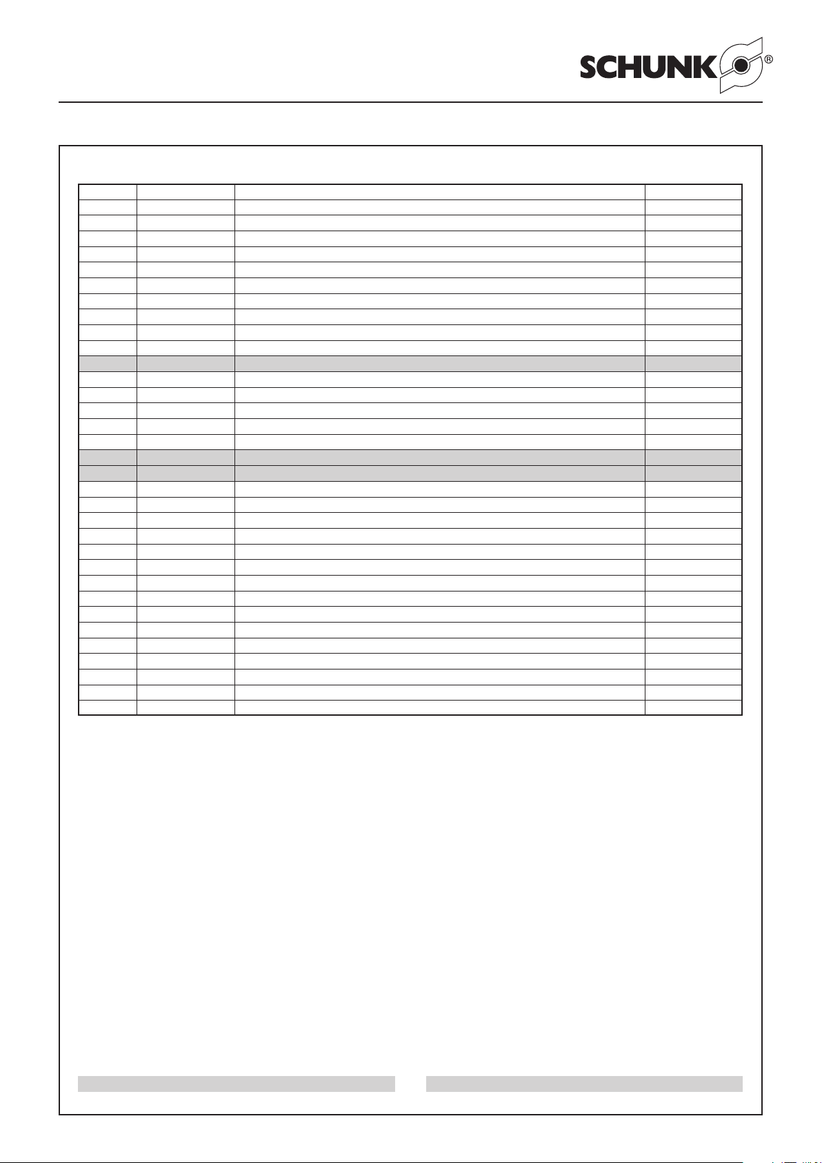
Ersatzteilstückliste PGN-plus 64 Spare part list PGN-plus 64
Pos. / item Ident-Nr. / Id. No. Bezeichnung / Description Menge / Quantity
1* 5511 241 Gehäuse / Housing 1
2* 5511 249 Grundbacke - Hub 1 / Base jaw - Stroke 1 2
3 5511 257 Kolben - Hub 1 / Piston - Stroke 1 1
4 5511 265 Deckel ohne GKS / Cover without GKS 1
5 5511 321 Abdeckblech / Cover plate 1
6 5511 273 Zylinderkolben ohne GKS - GKS IS / Cylinder piston without GKS - GKS IS 1
7* 5511 281 Grundbacke - Hub 2 / Base jaw - Stroke 2 2
8 5511 289 Kolben - Hub 2 / Piston - Stroke 2 1
9 5511 297 Deckel GKS / Cover GKS 1
10 5511 305 Zylinderkolben GKS AS / Cylinder piston GKS AS 1
12 9937 443 Flachdichtung / Flat seal 1
15 9937 473 Schaltnocke / Operating cam 2
16 9936 953 Halter für Schaltnocke / Bracket for operating cam 2
17 9646 015 Halter für Näherungsschalter / Bracket for proximity switch 2
19 5509 642 Zentrierhülse Ø 8 - GKS / Centering sleeve Ø 8 - GKS 2
25 9936 630 Druckfeder GKS / Pressure spring GKS 1
30 9936 629 Quad-Ring / Square ring 21.89 x 2.62 1
31 9610 111 Quad-Ring / Square ring 8.20 x 1.78 1
40 9664 015 Senkschraube / Countersunk screw M5 x 14 - ohne/without GKS - GKS IS 1
41 9907 425 Schraube / Screw M3 x 10 - ohne/without GKS 4
42 9682 135 Schraube / Screw M2 x 10 2
43 9660 110 Schraube / Screw M2 x 6 2
44 9664 029 Senkschraube / Countersunk screw M3 x 14 4
45 9660 091 Schraube / Screw M5 x 14 - GKS AS 1
46 9940 606 Schraube / Screw M3 x 20 - GKS 4
47 9664 032 Senkschraube / Countersunk screw M2.5 x 4 4
48 9936 175 Gewindestift / Set-screw M5 x 4 4
49 9670 505 Gewindestift / Set-screw M3 x 3 5
50 5511 490 Gehäuse mit Grundbacken - Hub 1 / Housing with base jaws - Stroke 1 1
50 5511 498 Gehäuse mit Grundbacken - Hub 2 / Housing with base jaws - Stroke 2 1
60 9936 070 Rundmagnet / Round magnet 1
98 5512 044 Beipack ohne GKS / Accessories supplied without GKS 1
99 5512 052 Beipack mit GKS / Accessories supplied with GKS 1
* Einzelteile sind aufeinander abgestimmt und können nicht vom
Kunden ausgetauscht werden.
GKS: Greifkraftsicherung
AS: Außensichern
IS: Innensichern
* Individual components are matched to one another so that the
customer should not replace them with different parts.
GKS: Gripping force safety device
AS: Safety device O.D. gripping
IS: Safety device I.D. gripping
Verschleißteile, empfohlen bei Wartung auszutauschen Wear parts; replacement during maintenance recommended
Page 16
16
Montage- und Betriebsanleitung für 2-Backen-Parallelgreifer
PGN-plus mit Werkzeugschnittstelle HSK/KM / Capto
Operating manual for 2-Finger Parallel Gripper
PGN-plus with tool interface HSK / KM /Capto
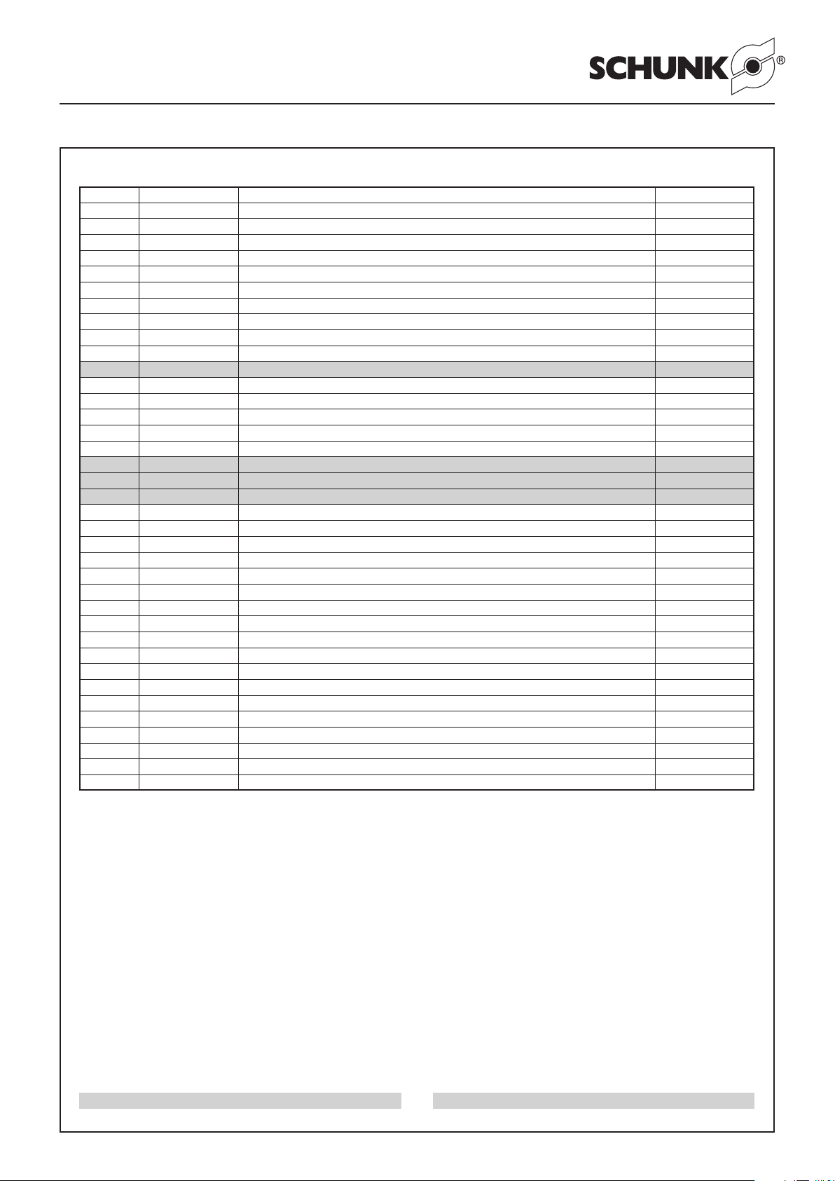
Ersatzteilstückliste PGN-plus 80 Spare part list PGN-plus 80
Pos. / item Ident-Nr. / Id. No. Bezeichnung / Description Menge / Quantity
1* 5511 242 Gehäuse / Housing 1
2* 5511 250 Grundbacke - Hub 1 / Base jaw - Stroke 1 2
3 5511 258 Kolben - Hub 1 / Piston - Stroke 1 1
4 5511 266 Deckel ohne GKS / Cover without GKS 1
5 5511 322 Abdeckblech / Cover plate 1
6 5511 274 Zylinderkolben ohne GKS - GKS IS / Cylinder piston without GKS - GKS IS 1
7* 5511282 Grundbacke - Hub 2 / Base jaw - Stroke 2 2
8 5511 290 Kolben - Hub 2 / Piston - Stroke 2 1
9 5511 298 Deckel GKS / Cover GKS 1
10 5511 306 Zylinderkolben GKS AS / Cylinder piston GKS AS 1
12 9937 444 Flachdichtung / Flat seal 1
15 9937 473 Schaltnocke / Operating cam 2
16 9936 953 Halter für Schaltnocke / Bracket for operating cam 2
17 5503 506 Halter für Näherungsschalter / Bracket for proximity switch 2
19 5509 642 Zentrierhülse Ø 8 - GKS / Centering sleeve Ø 8 - GKS 2
25 9937 112 Druckfeder GKS / Pressure spring GKS 1
30 9610 063 Quad-Ring / Square ring 29.82 x 2.62 1
31 9610 007 Quad-Ring / Square ring 12.42 x 1.78 1
33 9611 063 O-Ring / O-ring 6 x 1 1
40 9664 003 Senkschraube / Countersunk screw M6 x 16 - ohne/without GKS - GKS IS 1
41 9661 505 Schraube / Screw M4 x 10 - ohne/without GKS 4
42 9937 113 Schraube / Screw M2 x 14 - Hub / Stroke 1 2
42 9682 135 Schraube / Screw M2 x 10 - Hub / Stroke 2 2
43 9682 135 Schraube / Screw M2 x 10 - Hub / Stroke 1 2
43 9660 110 Schraube / Screw M2 x 6 - Hub / Stroke 2 2
44 9660 515 Schraube / Screw M3 x 12 4
45 9660 019 Schraube / Screw M6 x 20 - GKS AS 1
46 9940 605 Schraube / Screw M4 x 20 - GKS 4
47 9640 032 Senkschraube / Countersunk screw M2.5 x 4 4
48 9936 175 Gewindestift / Set-screw M5 x 4 4
49 9670 505 Gewindestift / Set-screw M3 x 3 3
50 5511491 Gehäuse mit Grundbacken - Hub 1 / Housing with base jaws - Stroke 1 1
50 5511 499 Gehäuse mit Grundbacken - Hub 2 / Housing with base jaws - Stroke 2 1
60 9936 070 Rundmagnet / Round magnet ohne/without GKS - GKS IS 1
60 9937 285 Rundmagnet / Round magnet GKS AS 1
98 5512 045 Beipack ohne GKS / Accessories supplied without GKS 1
99 5512 053 Beipack mit GKS / Accessories supplied with GKS 1
* Einzelteile sind aufeinander abgestimmt und können nicht vom
Kunden ausgetauscht werden.
GKS: Greifkraftsicherung
AS: Außensichern
IS: Innensichern
* Individual components are matched to one another so that the
customer should not replace them with different parts.
GKS: Gripping force safety device
AS: Safety device O.D. gripping
IS: Safety device I.D. gripping
Verschleißteile, empfohlen bei Wartung auszutauschen Wear parts; replacement during maintenance recommended
Page 17
17
Montage- und Betriebsanleitung für 2-Backen-Parallelgreifer
PGN-plus mit Werkzeugschnittstelle HSK/KM / Capto
Operating manual for 2-Finger Parallel Gripper
PGN-plus with tool interface HSK / KM /Capto
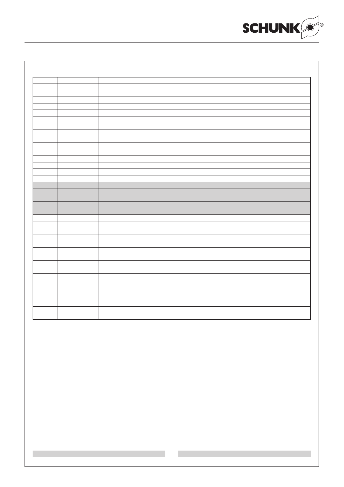
Ersatzteilstückliste PGN-plus 100 Spare part list PGN-plus 100
Pos. / item Ident-Nr. / Id. No. Bezeichnung / Description Menge / Quantity
1* 5511 243 Gehäuse / Housing 1
2* 5511 251 Grundbacke - Hub 1 / Base jaw - Stroke 1 2
3 5511 259 Kolben - Hub 1 / Piston - Stroke 1 1
4 5511 267 Deckel ohne GKS / Cover without GKS 1
5 5511 323 Abdeckblech / Cover plate 1
6 5511 275 Zylinderkolben ohne GKS - GKS IS / Cylinder piston without GKS - GKS IS 1
7* 5511 283 Grundbacke - Hub 2 / Base jaw - Stroke 2 2
8 5511 291 Kolben - Hub 2 / Piston - Stroke 2 1
9 5511 299 Deckel GKS / Cover GKS 1
10 5511 307 Zylinderkolben GKS AS / Cylinder piston GKS AS 1
15 9937 474 Schaltnocke / Operating cam 2
16 9936 955 Halter für Schaltnocke / Bracket for operating cam 2
17 5503 506 Halter für Näherungsschalter / Bracket for proximity switch 2
19 5509 643 Zentrierhülse Ø 10 - GKS / Centering sleeve Ø 10 - GKS 2
25 9936 631 Druckfeder GKS / Pressure spring GKS 1
30 9610 028 Quad-Ring / Square ring 39.34 x 2.62 1
31 9610 008 Quad-Ring / Square ring 14.00 x 1.78 1
32 9936 628 O-Ring / O-ring 48 x 1 1
33 9611 063 O-Ring / O-ring 6 x 1 1
34 9611 163 O-Ring / O-ring 4 x 1 4
40 9664 003 Senkschraube / Countersunk screw M5 x 14 - ohne/without GKS - GKS IS 1
41 9661 500 Schraube / Screw M4 x 12 - ohne/without GKS 4
42 9660 427 Schraube / Screw M3 x 16 2
43 9660 119 Schraube / Screw M3 x 12 2
44 9660 515 Schraube / Screw M3 x 12 4
45 9660 018 Schraube / Screw M6 x 18 - GKS AS 1
46 9907 483 Schraube / Screw M4 x 25 - GKS 4
47 9937 174 Senkschraube / Countersunk screw M3 x 5 4
48 9936 175 Gewindestift / Set-screw M5 x 4 6
49 9670 500 Gewindestift / Set-screw M4 x 4 2
50 5511 492 Gehäuse mit Grundbacken - Hub 1 / Housing with base jaws - Stroke 1 1
50 5511 500 Gehäuse mit Grundbacken - Hub 2 / Housing with base jaws - Stroke 2 1
60 9936 070 Rundmagnet / Round magnet ohne/without GKS - GKS IS 1
60 9937 285 Rundmagnet / Round magnet GKS AS 1
98 5512 046 Beipack ohne GKS / Accessories supplied without GKS 1
99 5512 054 Beipack mit GKS / Accessories supplied with GKS 1
* Einzelteile sind aufeinander abgestimmt und können nicht vom
Kunden ausgetauscht werden.
GKS: Greifkraftsicherung
AS: Außensichern
IS: Innensichern
* Individual components are matched to one another so that the
customer should not replace them with different parts.
GKS: Gripping force safety device
AS: Safety device O.D. gripping
IS: Safety device I.D. gripping
Verschleißteile, empfohlen bei Wartung auszutauschen Wear parts; replacement during maintenance recommended
Page 18
18
Montage- und Betriebsanleitung für 2-Backen-Parallelgreifer
PGN-plus mit Werkzeugschnittstelle HSK/KM / Capto
Operating manual for 2-Finger Parallel Gripper
PGN-plus with tool interface HSK / KM /Capto
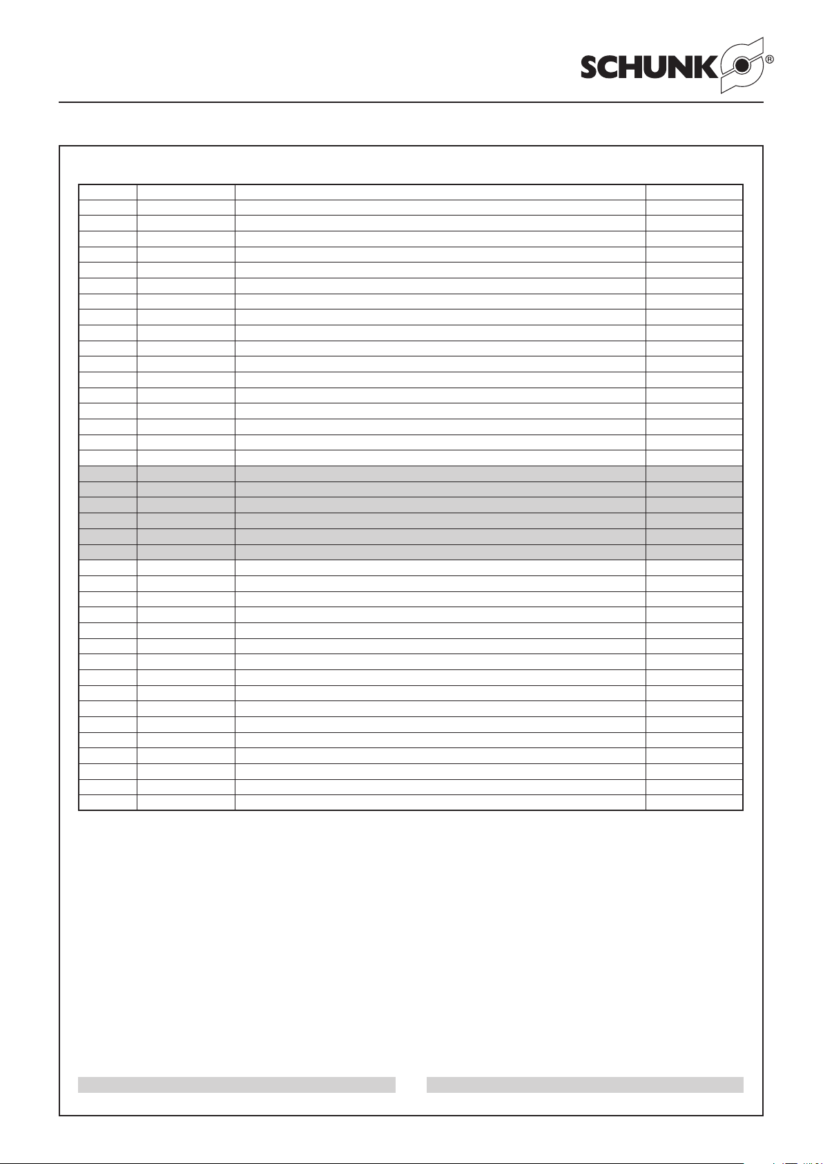
Ersatzteilstückliste PGN-plus 125 Spare part list PGN-plus 125
Pos. / item Ident-Nr. / Id. No. Bezeichnung / Description Menge / Quantity
1* 5511 244 Gehäuse / Housing 1
2* 5511 252 Grundbacke - Hub 1 / Base jaw - Stroke 1 2
3 5511 260 Kolben - Hub 1 / Piston - Stroke 1 1
4 5511 268 Deckel ohne GKS / Cover without GKS 1
5 5511 324 Abdeckblech / Cover plate 1
6 5511 276 Zylinderkolben ohne GKS - GKS IS / Cylinder piston without GKS - GKS IS 1
7* 5511 284 Grundbacke - Hub 2 / Base jaw - Stroke 2 2
8 5511 292 Kolben - Hub 2 / Piston - Stroke 2 1
9 5511 300 Deckel GKS / Cover GKS 1
10 5511 308 Zylinderkolben GKS AS / Cylinder piston GKS AS 1
11 5511 485 Distanzbolzen GKS AS / Distance bolt GKS AS
15 9937 474 Schaltnocke / Operating cam 2
16 9936 955 Halter für Schaltnocke / Bracket for operating cam 2
17 5503 506 Halter für Näherungsschalter / Bracket for proximity switch 2
19 5509 644 Zentrierhülse Ø 12 - GKS / Centering sleeve Ø 12 - GKS 2
25 9936 821 Druckfeder GKS AS / Pressure spring GKS AS 1
25 9936 822 Druckfeder GKS IS / Pressure spring GKS IS 1
30 9936 343 Quad-Ring / Square ring 50.47 x 2.62 1
31 9610 018 Quad-Ring / Square ring 16.00 x 2.62 1
32 9935 467 O-Ring / O-ring 60 x 1.5 - ohne/without GKS 1
32 9935 467 O-Ring / O-ring 60 x 1.5 - GKS 2
33 9611 044 O-Ring / O-ring 10 x 1 1
34 9611 227 O-Ring / O-ring 5 x 1 4
40 9682 117 Senkschraube / Countersunk screw M8 x 25 - ohne/without GKS - GKS IS 1
41 9907 607 Schraube / Screw M5 x 16 - ohne/without GKS 4
42 9660 425 Schraube / Screw M3 x 20 - Hub / Stroke 1 2
42 9660 427 Schraube / Screw M3 x 16 - Hub / Stroke 2 2
43 9660 003 Schraube / Screw M3 x 16 - Hub / Stroke 1 2
43 9660 119 Schraube / Screw M3 x 12 - Hub / Stroke 2 2
44 9660 413 Schraube / Screw M3 x 14 4
45 9660 030 Schraube / Screw M8 x 45 - GKS AS 1
46 9907 486 Schraube / Screw M5 x 35 - GKS 4
47 9937 174 Senkschraube / Countersunk screw M3 x 5 4
48 9936 175 Gewindestift / Set-screw M5 x 4 6
50 5511 493 Gehäuse mit Grundbacken - Hub 1 / Housing with base jaws - Stroke 1 1
50 5511 501 Gehäuse mit Grundbacken - Hub 2 / Housing with base jaws - Stroke 2 1
60 9936 070 Rundmagnet / Round magnet 1
98 5512 047 Beipack ohne GKS / Accessories supplied without GKS 1
99 5512 055 Beipack mit GKS / Accessories supplied with GKS 1
* Einzelteile sind aufeinander abgestimmt und können nicht vom
Kunden ausgetauscht werden.
GKS: Greifkraftsicherung
AS: Außensichern
IS: Innensichern
* Individual components are matched to one another so that the
customer should not replace them with different parts.
GKS: Gripping force safety device
AS: Safety device O.D. gripping
IS: Safety device I.D. gripping
Verschleißteile, empfohlen bei Wartung auszutauschen Wear parts; replacement during maintenance recommended
Page 19
19
Montage- und Betriebsanleitung für 2-Backen-Parallelgreifer
PGN-plus mit Werkzeugschnittstelle HSK/KM / Capto
Operating manual for 2-Finger Parallel Gripper
PGN-plus with tool interface HSK / KM /Capto
Ersatzteilstückliste PGN-plus 160 Spare part list PGN-plus 160
Pos. / item Ident-Nr. / Id. No. Bezeichnung / Description Menge / Quantity
1* 5511 245 Gehäuse / Housing 1
2* 5511 253 Grundbacke - Hub 1 / Base jaw - Stroke 1 2
3 5511 261 Kolben - Hub 1 / Piston - Stroke 1 1
4 5512 269 Deckel ohne GKS / Cover without GKS 1
5 5511 325 Abdeckblech / Cover plate 1
6 5511 277 Zylinderkolben ohne GKS - GKS IS / Cylinder piston without GKS - GKS IS 1
7* 5511 285 Grundbacke - Hub 2 / Base jaw - Stroke 2 2
8 5511 293 Kolben - Hub 2 / Piston - Stroke 2 1
9 5511 301 Deckel GKS / Cover GKS 1
10 5511 309 Zylinderkolben GKS AS / Cylinder piston GKS AS 1
11 5511 486 Distanzbolzen GKS AS / Distance bolt GKS AS 1
15 9937 475 Schaltnocke / Operating cam 2
16 9936 956 Halter für Schaltnocke / Bracket for operating cam 2
17 5503 506 Halter für Näherungsschalter / Bracket for proximity switch 2
19 5509 644 Zentrierhülse Ø 12 - GKS / Centering sleeve Ø 12 - GKS 2
25 9936 823 Druckfeder GKS AS / Pressure spring GKS AS 1
25 9936 824 Druckfeder GKS IS / Pressure spring GKS IS 1
30 9935 921 Quad-Ring / Square ring 66.34 x 2.62 1
31 9610 021 Quad-Ring / Square ring 20.29 x 2.62 1
32 9936 847 O-Ring / O-ring 76 x 1.5 1
33 9935 302 O-Ring / O-ring 11 x 1 - ohne/without GKS 1
33 9935 302 O-Ring / O-ring 11 x 1 - GKS 2
34 9611 227 O-Ring / O-ring 5 x 1 4
40 9682 119 Senkschraube / Countersunk screw M10 x 30 - ohne/without GKS - GKS IS 1
41 9907 607 Schraube / Screw M5 x 16 - ohne/without GKS 4
42 9907 483 Schraube / Screw M4 x 25 - Hub / Stroke 1 2
42 9907 586 Schraube / Screw M4 x 18 - Hub / Stroke 2 2
43 9660 136 Schraube / Screw M4 x 20 - Hub / Stroke 1 2
43 9660 133 Schraube / Screw M4 x 14 - Hub / Stroke 2 2
44 9660 413 Schraube / Screw M3 x 14 4
45 9660 402 Schraube / Screw M10 x 55 - GKS AS 1
46 9907 486 Schraube / Screw M5 x 35 - GKS 4
47 9937 174 Senkschraube / Countersunk screw M3 x 5 4
48 9936 175 Gewindestift / Set-screw M5 x 4 6
50 5511 494 Gehäuse mit Grundbacken - Hub 1 / Housing with base jaws - Stroke 1 1
50 5511 502 Gehäuse mit Grundbacken - Hub 2 / Housing with base jaws - Stroke 2 1
60 9936 070 Rundmagnet / Round magnet 1
98 5512 048 Beipack ohne GKS / Accessories supplied without GKS 1
99 5512 056 Beipack mit GKS / Accessories supplied with GKS 1
* Einzelteile sind aufeinander abgestimmt und können nicht vom
Kunden ausgetauscht werden.
GKS: Greifkraftsicherung
AS: Außensichern
IS: Innensichern
* Individual components are matched to one another so that the
customer should not replace them with different parts.
GKS: Gripping force safety device
AS: Safety device O.D. gripping
IS: Safety device I.D. gripping
Verschleißteile, empfohlen bei Wartung auszutauschen Wear parts; replacement during maintenance recommended
Page 20
20
Montage- und Betriebsanleitung für 2-Backen-Parallelgreifer
PGN-plus mit Werkzeugschnittstelle HSK/KM / Capto
Operating manual for 2-Finger Parallel Gripper
PGN-plus with tool interface HSK / KM /Capto
Ersatzteilstückliste PGN-plus 200 Spare part list PGN-plus 200
Pos. / item Ident-Nr. / Id. No. Bezeichnung / Description Menge / Quantity
1* 5511 479 Gehäuse / Housing 1
2* 5511 480 Grundbacke - Hub 1 / Base jaw - Stroke 1 2
3 5511 481 Kolben - Hub 1 / Piston - Stroke 1 1
4 5511 489 Deckel ohne GKS / Cover without GKS 1
5 5511 326 Abdeckblech / Cover plate 1
6 5511 497 Zylinderkolben ohne GKS - GKS IS / Cylinder piston without GKS - GKS IS 1
7* 5511 505 Grundbacke - Hub 2 / Base jaw - Stroke 2 2
8 5511 507 Kolben - Hub 2 / Piston - Stroke 2 1
9 5511 509 Deckel GKS / Cover GKS 1
10 5511 510 Zylinderkolben GKS AS / Cylinder piston GKS AS 1
11 5511 487 Distanzbolzen GKS AS / Distance bolt GKS AS 1
15 9937 475 Schaltnocke / Operating cam 2
16 9936 956 Halter für Schaltnocke / Bracket for operating cam 2
17 9645 001 Halter für Näherungsschalter / Bracket for proximity switch 2
19 5509 645 Zentrierhülse Ø 14 - GKS / Centering sleeve Ø 14 - GKS 2
25 Druckfeder GKS AS / Pressure spring GKS AS 1
25 Druckfeder GKS IS / Pressure spring GKS IS 1
30 9610 072 Quad-Ring / Square ring 85.32 x 3.53 1
31 9610 036 Quad-Ring / Square ring 25.00 x 3.53 1
32 9936 043 O-Ring / O-ring 106.00 x 2.00 1
33 9935 303 O-Ring / O-ring 14.00 x 1.00 - ohne/without GKS 1
33 9935 303 O-Ring / O-ring 14.00 x 1.00 - GKS 2
34 9611 227 O-Ring / O-ring 5.00 x 1.00 4
40 9664 033 Senkschraube / Countersunk screw M12 x 30 - ohne/without GKS - GKS IS 1
41 9907 607 Schraube / Screw M5 x 16 - ohne/without GKS 8
42 9936 687 Schraube / Screw M4 x 30 - Hub / Stroke 1 2
42 9907 483 Schraube / Screw M4 x 25 - Hub / Stroke 2 2
43 9660 219 Schraube / Screw M4 x 25 - Hub / Stroke 1 2
43 9660 136 Schraube / Screw M4 x 20 - Hub / Stroke 2 2
44 9660 413 Schraube / Screw M3 x 14 4
45 9660 403 Schraube / Screw M12 x 65 / GKS AS 1
46 9660 422 Schraube / Screw M8 x 50 / GKS 4
47 9664 501 Senkschraube / Countersunk screw M3 x 8 4
48 9936 175 Gewindestift / Set-screw M5 x 4 6
50 5511495 Gehäuse mit Grundbacken - Hub 1 / Housing with base jaws - Stroke 1 1
50 5511 503 Gehäuse mit Grundbacken - Hub 2 / Housing with base jaws - Stroke 2 1
60 9936 070 Rundmagnet / Round magnet 1
98 5512 049 Beipack ohne GKS / Accessories supplied without GKS 1
99 5512 057 Beipack mit GKS / Accessories supplied with GKS 1
* Einzelteile sind aufeinander abgestimmt und können nicht vom
Kunden ausgetauscht werden.
GKS: Greifkraftsicherung
AS: Außensichern
IS: Innensichern
* Individual components are matched to one another so that the
customer should not replace them with different parts.
GKS: Gripping force safety device
AS: Safety device O.D. gripping
IS: Safety device I.D. gripping
Verschleißteile, empfohlen bei Wartung auszutauschen Wear parts; replacement during maintenance recommended
Page 21
21
Montage- und Betriebsanleitung für 2-Backen-Parallelgreifer
PGN-plus mit Werkzeugschnittstelle HSK/KM / Capto
Operating manual for 2-Finger Parallel Gripper
PGN-plus with tool interface HSK / KM /Capto
Ersatzteilstückliste PGN-plus 300 Spare part list PGN-plus 300
Pos. / item Ident-Nr. / Id. No. Bezeichnung / Description Menge / Quantity
1* 5511 511 Gehäuse / Housing 1
2* 5511 512 Grundbacke - Hub 1 / Base jaw - Stroke 1 2
3 5511 513 Kolben - Hub 1 / Piston - Stroke 1 1
4 5511 514 Deckel ohne GKS / Cover without GKS 1
5 5511 327 Abdeckblech / Cover plate 1
6 5511 515 Zylinderkolben ohne GKS - GKS IS / Cylinder piston without GKS - GKS IS 1
7* 5511 516 Grundbacke - Hub 2 / Base jaw - Stroke 2 2
8 5511 517 Kolben - Hub 2 / Piston - Stroke 2 1
9 5511 518 Deckel GKS / Cover GKS 1
10 5511 519 Zylinderkolben GKS AS / Cylinder piston GKS AS 1
11 5511 488 Distanzbolzen GKS AS / Distance bolt GKS AS 1
15 9937 475 Schaltnocke / Operating cam 2
16 9936 956 Halter für Schaltnocke / Bracket for operating cam 2
17 5503 506 Halter für Näherungsschalter / Bracket for proximity switch 2
19 5509 647 Zentrierhülse Ø 22 - GKS / Centering sleeve Ø 22 - GKS 2
25 9980 808 Druckfeder GKS AS / Pressure spring GKS AS 1
25 9980 805 Druckfeder GKS IS / Pressure spring GKS IS 1
30 9610 073 Quad-Ring / Square ring 120.25 x 3.53 1
31 9938 273 Quad-Ring / Square ring 29.74 x 3.53 1
32 9937 935 O-Ring / O-ring 140.00 x 2.00 1
33 9611 227 O-Ring / O-ring 18.00 x 1.00 1
34 9611 227 O-Ring / O-ring 5.00 x 1.00 4
40 9682 123 Senkschraube / Countersunk screw M16 x 40 - ohne/without GKS - GKS IS 1
41 9907 607 Schraube / Screw M5 x 16 - ohne/without GKS 8
42 9935 438 Schraube / Screw M4 x 40 - Hub / Stroke 1 2
43 9935 472 Schraube / Screw M4 x 35 - Hub / Stroke 2 2
44 9660 413 Schraube / Screw M3 x 14 4
45 9937 373 Schraube / Screw M16 x 75 - GKS AS 1
46 9660 422 Schraube / Screw M8 x 50 - GKS 4
47 9664 501 Senkschraube / Countersunk screw M3 x8 4
48 9936 175 Gewindestift / Set-screw M5 x 4 6
50 5511 496 Gehäuse mit Grundbacken - Hub 1 / Housing with base jaws - Stroke 1 1
50 5511 504 Gehäuse mit Grundbacken - Hub 2 / Housing with base jaws - Stroke 2 1
60 9938 063 Rundmagnet / Round magnet 2
98 5512 050 Beipack ohne GKS / Accessories supplied without GKS 1
99 5512 058 Beipack mit GKS / Accessories supplied with GKS 1
* Einzelteile sind aufeinander abgestimmt und können nicht vom
Kunden ausgetauscht werden.
GKS: Greifkraftsicherung
AS: Außensichern
IS: Innensichern
* Individual components are matched to one another so that the
customer should not replace them with different parts.
GKS: Gripping force safety device
AS: Safety device O.D. gripping
IS: Safety device I.D. gripping
Verschleißteile, empfohlen bei Wartung auszutauschen Wear parts; replacement during maintenance recommended
Page 22

Montage- und Betriebsanleitung für 2-Backen-Parallelgreifer
l
1
± 0.02
A
Ø d
3
B
C
0.02
0.02
t
3
Ø 15
E
H8
Ø d
2
D
H8
l
2
± 0.02
Ø d1
h7
B
B
A
A
Schnitt A – A
Cross
section A – A
Schnitt B – B
Cross
section B – B
t
2
t
1
1x 45°
PGN-plus mit Werkzeugschnittstelle HSK/KM / Capto
Operating manual for 2-Finger Parallel Gripper
PGN-plus with tool interface HSK / KM /Capto
10. Montagevorrichtung 10. Assembly device
Type A B C D E l1 l2 d1 d2 d3 t1 t2 t3 Schraube/Screw
PGN+ 64 52 36 27 31 24 42 27 8 5.5 10 23 2.5 7 M5 x 30
PGN+ 80 63 42 32 42 30 52 32 8 5.5 10 25 2.5 6 M5 x 35
PGN+ 100 81 50 38 54 36 66 38 10 6.6 11 30 3.5 7 M6 x 40
11. Zubehör (auf besondere Bestellung)
11.1 Einstellsatz
Der Einstellsatz für HSK/KM/Capto-Greifer dient zum Einstellen
des Effektivdruckes, der tatsächlich im Greifer wirkt.
11.2 Weiteres Zubehör
Prinzipiell ist das gesamte Zubehör des PGN-plus anbaubar.
Prüfen Sie aber bitte, ob dies bei Einsatz an der Werkzeugspindel
sinnvoll ist.
Näheres entnehmen Sie bitte dem Hauptkatalog/ der Bedienungsanleitung des Greifers.
11. Accessories (upon separate order)
11.1 Adjustment set
The adjustment set for HSK / KM /Capto-grippers are used for
adjusting the pressure, effecting the gripper.
11.2 Further Accessories
Basically, the complete range of accessories for PGN-plus can
be attached. Please check, if the use at the tool spindle makes
sense.
You will find further information in our main catalogue/ in the
operation manual of the gripper.
22
 Loading...